sensor AUDI S5 2008 8T / 1.G Owner's Manual
[x] Cancel search | Manufacturer: AUDI, Model Year: 2008, Model line: S5, Model: AUDI S5 2008 8T / 1.GPages: 294, PDF Size: 12.13 MB
Page 134 of 294
Downloaded from www.Manualslib.com manuals search engine Audi parking system 132
Activating
– Engage reverse gear to automatically activate the
parking system advanced, or
– Press the switch
in the centre console ⇒page 129,
fig. 141 to manually activate the parking system
advanced. You will hear a short beep to confirm that the
parking system has been activated. The indicator lamp in
the switch will light up.
Deactivating
– Drive forwards faster than approx. 10 km/h, or
– Switch off the ignition to automatically deactivate the
complete parking system, or
– Press the switch
in the centre console ⇒page 129,
fig. 141 to deactivate the parking system advanced. The
indicator lamp in the switch will go out.
Activate the system manually if you are driving forwards and would
like the system to give a warning as you approach potential obsta-
cles, for instance when parking.
The measuring range of the sensors in the front and rear bumpers
starts at approximately:Warning beeps
The warning beeps are produced by sound boxes. The volume and
pitch of the beeps can be adjusted in the MMI ⇒page 139.
Mute function
An acoustic proximity warning is cancelled when you apply the
parking brake or move the selector lever of the automatic gearbox
to position P. However, the system remains active. The warning
beeps will start again as soon as you release the parking brake or
move the selector lever out of position P if the system has detected
an obstacle.
Reversing/driving forwards
When the vehicle is reversing/driving forwards, the system starts to
beep if it registers an obstacle within its detection range (see
above). The warnings will beep increasingly rapidly as the vehicle
approaches the obstacle.
When the vehicle is less than approx. 0.30 m away from the obstacle
the warning tone will sound continuously. From here at the latest,
the driver should then not reverse/drive forwards any further.
The volume of the warning beeps will be gradually reduced after
about 4 seconds if the vehicle remains at a constant distance from
a detected obstacle (it will not be reduced if the obstacle is closer
than 0.30 m). The warnings will then return to the normal volume if
the vehicle approaches the detected obstacle again.
Parking
If the parking manoeuvre involves shunting backwards and
forwards, the warning sound will be switched off temporarily while
you change gear. The proximity graphic will, however, still be
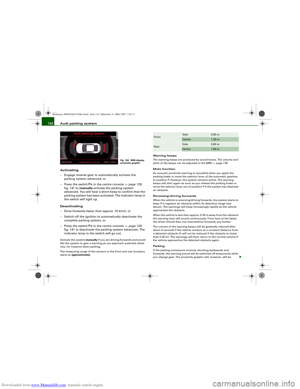
Fig. 144 MMI display:
proximity graphic
Front
Side
0.90 m
Centre
1.20 m
Rear
Side
0.60 m
Centre
1.60 m
document_0900452a81793dcc.book Seite 132 Mittwoch, 21. März 2007 5:42 17
Page 135 of 294
Downloaded from www.Manualslib.com manuals search engine Audi parking system133
Controls
Safety
Driving tips
General maintenance
Self-help
Technical data displayed on the MMI screen. The warnings will then return to the
normal volume if the vehicle approaches the detected obstacle
again.
Graphic display
The segments in the MMI display indicate the distance between the
vehicle and an obstacle. The number of segments shown depends
on the obstacle in front of or behind the vehicle. The closer the
vehicle gets to the obstacle the closer the segments move towards
the vehicle in the graphic ⇒page 132, fig. 144. At the latest when
the penultimate segment is highlighted the vehicle has reached the
danger (collision) zone. The driver should then not move back-
wards/forwards any further ⇒.
The graphic display in the MMI screen ⇒page 140 can be switched
off. The acoustic proximity warning will, however, remain activated.
The graphic display will be deactivated as soon as you press a func-
tion selector button on the MMI control console. The graphic
display in the MMI screen can also be switched on again manually
using the switch
. For more information on the MMI control
console please refer to the MMI Operating Manual.
Reversing camera (Rear View)
The mirrored image of the picture supplied by the reversing camera
⇒page 136, fig. 149 is shown in the MMI display. The picture
supplied by the reversing camera also includes orientation lines
and area markings which are projected onto the image to assist you
when parking ⇒page 134. The red line in the picture ⇒page 134,
fig. 145/⇒page 134, fig. 146 shows the collision zone. From here at
the latest, the driver should not reverse any further ⇒.
If your vehicle is near an obstacle, the proximity graphic will also
appear in the reversing camera image. This superimposed graphic
helps the driver to localise the critical area of the vehicle.
If the MMI screen is showing the graphic display you can switch to
the image of the reversing camera by pressing the control button
for the function Rear View ⇒page 132, fig. 144.If the MMI screen is showing the image of the reversing camera you
can switch to the graphic display by pressing the control button for
the function Graphic ⇒page 136, fig. 149.
The image of the reversing camera in the MMI screen ⇒page 140
can be switched off. The acoustic proximity warning will, however,
remain activated.
The image of the reversing camera will be deactivated as soon as
you press a function selector button on the MMI control console.
The image of the reversing camera will be shown again the next
time you park the vehicle. The image of the reversing camera can
also be switched on again manually using the switch
. For more
information on the MMI control console please refer to the MMI
Operating Manual.
WARNING
•
The sensors have blind spots in which obstacles are not regis-
tered. It is particularly important to ensure that there are no small
children or animals near the vehicle, as the sensors may not
always be able to detect them.
•
The parking aid cannot replace the full concentration of the
driver. The driver is always responsible for safety during parking
and other manoeuvres. Always keep a close watch on the area
around the vehicle.
•
Please note that low obstacles detected by the system may no
longer be registered by the sensors as the car moves closer, so the
system will not give any further warning. Certain kinds of obsta-
cles (such as wire fences, chains, thin painted posts or trailer draw
bars, etc.) may not always be detected by the system (accident
risk).Note
•
There is a slight delay in the picture display.
•
You can change the settings for the graphic display and the
reversing camera in the MMI ⇒page 140.
document_0900452a81793dcc.book Seite 133 Mittwoch, 21. März 2007 5:42 17
Page 136 of 294
Downloaded from www.Manualslib.com manuals search engine Audi parking system 134•
To ensure that the acoustic parking aid works properly, the
sensors and the lens of the reversing camera must be kept clean
and free of snow and ice. Please observe the additional notes from
⇒page 143 onwards.
•
Please refer to the notes on towing ⇒page 138.
Applies to vehicles: with parking system advancedReversing camera (Rear View)
The reversing camera image in the MMI display shows the
area behind the vehicle.
Parking mode
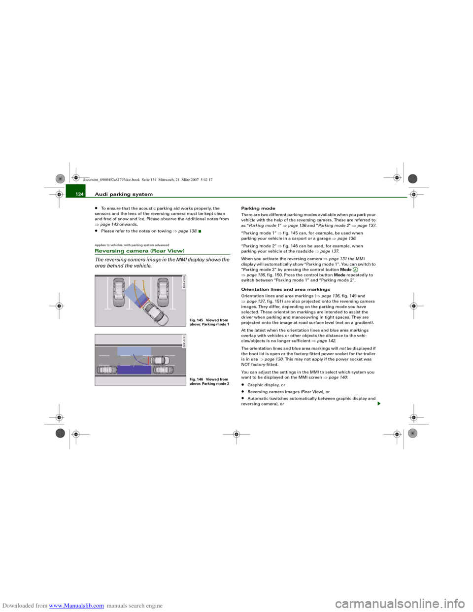
There are two different parking modes available when you park your
vehicle with the help of the reversing camera. These are referred to
as “Parking mode 1” ⇒page 136 and “Pa r k i n g m od e 2” ⇒page 137.
“Parking mode 1” ⇒fig. 145 can, for example, be used when
parking your vehicle in a carport or a garage ⇒page 136.
“Parking mode 2” ⇒fig. 146 can be used, for example, when
parking your vehicle at the roadside ⇒page 137.
When you activate the reversing camera ⇒page 131 the MMI
display will automatically show “Parking mode 1”. You can switch to
“Parking mode 2” by pressing the control button Mode
⇒page 136, fig. 150. Press the control button Mode repeatedly to
switch between “Parking mode 1” and “Parking mode 2”.
Orientation lines and area markings
Orientation lines and area markings (⇒page 136, fig. 149 and
⇒page 137, fig. 151) are also projected onto the reversing camera
images. They differ, depending on the parking mode you have
selected. These orientation markings are intended to assist the
driver when parking and manoeuvring in tight spaces. They are
projected onto the image at road surface level (not on a gradient).
At the latest when the orientation lines and blue area markings
overlap with vehicles or other objects the distance to the vehi-
cles/objects is no longer sufficient ⇒page 142.
The orientation lines and blue area markings will not be displayed if
the boot lid is open or the factory-fitted power socket for the trailer
is in use ⇒page 138. This may not apply if the power socket was
NOT factory-fitted.
You can adjust the settings in the MMI to select which system you
want to be displayed on the MMI screen ⇒page 140:•
Graphic display, or
•
Reversing camera images (Rear View), or
•
Automatic (switches automatically between graphic display and
reversing camera), or
Fig. 145 Viewed from
above: Parking mode 1Fig. 146 Viewed from
above: Parking mode 2
AA
document_0900452a81793dcc.book Seite 134 Mittwoch, 21. März 2007 5:42 17
Page 137 of 294
Downloaded from www.Manualslib.com manuals search engine Audi parking system135
Controls
Safety
Driving tips
General maintenance
Self-help
Technical data
•
Off (no display).
The reversing camera can be switched on and off in the MMI
⇒page 140. The acoustic proximity warning will, however, remain
activated.
WARNING
•
The reversing camera has blind spots in which obstacles are
not registered. It is particularly important to ensure that there are
no small children or animals near the vehicle, as the reversing
camera may not always be able to detect them (accident risk).
•
The parking aid cannot replace the full concentration of the
driver. The driver is always responsible for safety during parking
and other manoeuvres. Always keep a close watch on the area
around the vehicle.
•
Please note that low obstacles detected by the system may no
longer be registered by the sensors as the car moves closer, so the
system will not give any further warning. Certain kinds of obsta-
cles (such as wire fences, chains, thin painted posts or trailer draw
bars, etc.) may not always be detected by the system (accident
risk).Note
•
There is a slight delay in the picture display.
•
To ensure that the reversing camera works properly, the lens of
the camera ⇒page 131, fig. 143 must be kept clean and free of
snow and ice. Please observe the additional notes on ⇒page 143.
•
If the boot lid is open the angle covered by the camera will
change. For this reason, the image of the reversing camera will then
be shown without orientation lines and blue area markings.
•
Please refer to the notes on towing ⇒page 138.
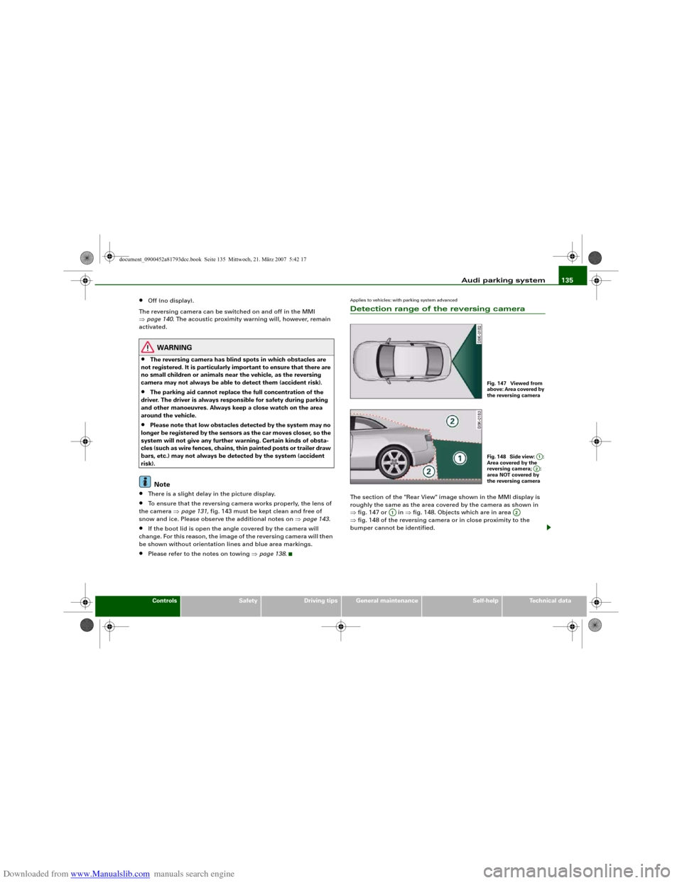
Applies to vehicles: with parking system advancedDetection range of the reversing cameraThe section of the "Rear View" image shown in the MMI display is
roughly the same as the area covered by the camera as shown in
⇒fig. 147 or in ⇒fig. 148. Objects which are in area
⇒fig. 148 of the reversing camera or in close proximity to the
bumper cannot be identified.
Fig. 147 Viewed from
above: Area covered by
the reversing cameraFig. 148 Side view: :
Area covered by the
reversing camera; :
area NOT covered by
the reversing camera
A1A2
A1
A2
document_0900452a81793dcc.book Seite 135 Mittwoch, 21. März 2007 5:42 17
Page 140 of 294
Downloaded from www.Manualslib.com manuals search engine Audi parking system 138
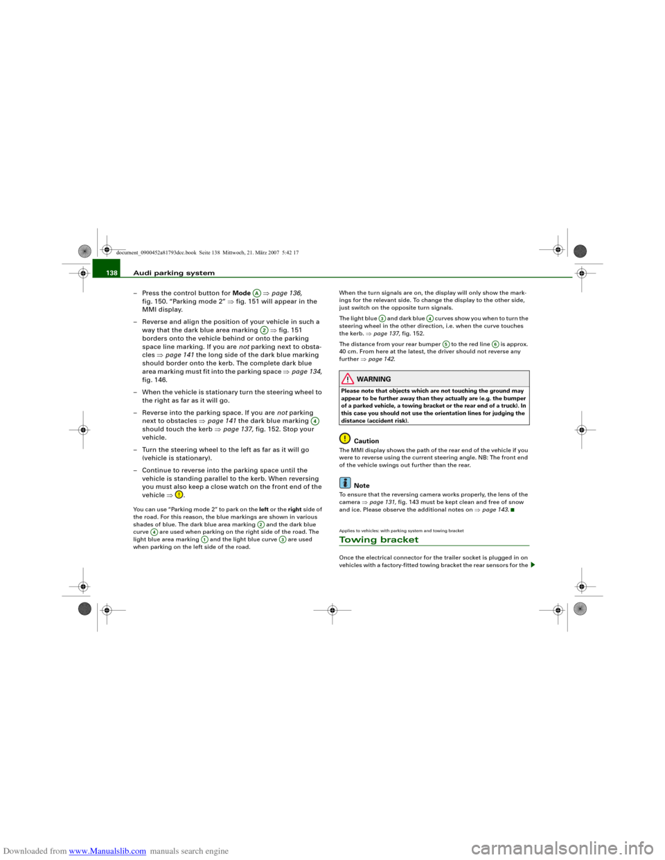
– Press the control button for Mode ⇒page 136,
fig. 150. “Parking mode 2” ⇒fig. 151 will appear in the
MMI display.
– Reverse and align the position of your vehicle in such a
way that the dark blue area marking ⇒fig. 151
borders onto the vehicle behind or onto the parking
space line marking. If you are not parking next to obsta-
cles ⇒page 141 the long side of the dark blue marking
should border onto the kerb. The complete dark blue
area marking must fit into the parking space ⇒page 134,
fig. 146.
– When the vehicle is stationary turn the steering wheel to
the right as far as it will go.
– Reverse into the parking space. If you are not parking
next to obstacles ⇒page 141 the dark blue marking
should touch the kerb ⇒page 137, fig. 152. Stop your
vehicle.
– Turn the steering wheel to the left as far as it will go
(vehicle is stationary).
– Continue to reverse into the parking space until the
vehicle is standing parallel to the kerb. When reversing
you must also keep a close watch on the front end of the
vehicle ⇒.You can use “Parking mode 2” to park on the left or the right side of
the road. For this reason, the blue markings are shown in various
shades of blue. The dark blue area marking and the dark blue
curve are used when parking on the right side of the road. The
light blue area marking and the light blue curve are used
when parking on the left side of the road.When the turn signals are on, the display will only show the mark-
ings for the relevant side. To change the display to the other side,
just switch on the opposite turn signals.
The light blue and dark blue curves show you when to turn the
steering wheel in the other direction, i.e. when the curve touches
the kerb. ⇒page 137, fig. 152.
The distance from your rear bumper to the red line is approx.
40 cm. From here at the latest, the driver should not reverse any
further ⇒page 142.
WARNING
Please note that objects which are not touching the ground may
appear to be further away than they actually are (e.g. the bumper
of a parked vehicle, a towing bracket or the rear end of a truck). In
this case you should not use the orientation lines for judging the
distance (accident risk).
Caution
The MMI display shows the path of the rear end of the vehicle if you
were to reverse using the current steering angle. NB: The front end
of the vehicle swings out further than the rear.
Note
To ensure that the reversing camera works properly, the lens of the
camera ⇒page 131, fig. 143 must be kept clean and free of snow
and ice. Please observe the additional notes on ⇒page 143.Applies to vehicles: with parking system and towing bracketTo w i n g b r a c k e tOnce the electrical connector for the trailer socket is plugged in on
vehicles with a factory-fitted towing bracket the rear sensors for the
AAA2
A4
A2
A4
A1
A3
A3
A4
A5
A6
document_0900452a81793dcc.book Seite 138 Mittwoch, 21. März 2007 5:42 17
Page 168 of 294
Downloaded from www.Manualslib.com manuals search engine Airbag system 166Airbag systemDescription of airbag systemGeneral notes on airbag system
The airbag is an integral part of the car's passive safety
system.In conjunction with the three-point seat belts, the airbag system
gives the front occupants additional protection for the head and
chest in the event of a severe frontal collision.
In a severe side collision the side airbags and the head-protection
airbags reduce the risk of injury to the occupants in the areas of the
body facing the impact ⇒.
In addition to their normal function of protecting the occupants in a
collision, the seat belts also hold them in a position where the
airbags can inflate properly and provide maximum protection.
The airbag system will only work with the ignition on. The airbag
system is monitored electronically; the airbag warning lamp indi-
cates whether the system is functioning properly.
The main parts of the airbag system are:•
the electronic monitoring system (control unit and sensors),
•
the two front airbags,
•
the front side airbags and head-protection airbags,
•
The airbag warning lamp in the instrument cluster.
There is a fault in the airbag system if the warning
lamp
•
does not come on when the ignition is switched on,
•
does not go out about 4 seconds after the ignition is switched
on,
•
goes out and then comes on again after the ignition is switched
on,
•
comes on or flickers while the car is moving.
WARNING
•
The airbags are not a substitute for the seat belts; they are an
integral part of the car's overall passive safety system. The airbags
can only offer effective protection if the occupants are wearing
their seat belts. For this reason it is very important to wear the
seat belts at all times ⇒page 160, “Why is it so important to use
seat belts?”.
•
The seat belts and airbags can only provide maximum protec-
tion if the occupants are seated correctly ⇒page 70, “Seats and
storage”.
•
If you do not wear a seat belt, if you lean forward, or are not
seated correctly while the vehicle is in motion, you are at greater
risk of injury should the airbag system be triggered in an accident.
•
Components of the airbag system are located in various parts
of the vehicle. If repairs to other vehicle components make it
necessary to perform work on the airbag system or to remove or
install parts of the airbag system, this may cause damage to the
airbag system. As a result, the airbags may not inflate correctly or
may not be triggered at all in an accident situation. For this reason,
you should always have the work carried out by a qualified work-
shop.
•
If a fault should occur in the airbag system, have the system
checked immediately by a qualified workshop. Otherwise the
system may fail to trigger in an accident.
•
Do not attempt to modify components of the airbag system in
any way.
•
Never make any alterations to the front bumper or the body.
document_0900452a81793dcc.book Seite 166 Mittwoch, 21. März 2007 5:42 17
Page 169 of 294
Downloaded from www.Manualslib.com manuals search engine Airbag system167
Controls
Safety
Driving tips
General maintenance
Self-help
Technical data
•
The airbag system can only be activated once; if the airbag has
been triggered, the system must be replaced. Should the airbag
system or airbag modules have to be replaced, the qualified work-
shop carrying out the replacement will document all details in the
appropriate section of the Service Schedule.
•
If you sell the vehicle, please remember to pass on the
complete Service Wallet to the new owner. If any of the airbags
have been deactivated, it is important that the new owner is also
given the relevant documents.
•
The relevant safety requirements must be observed when the
vehicle or components of the airbag or belt tensioner systems are
scrapped.
•
In an accident in which one or more airbags are triggered the
alternator and the starter are - for safety reasons - both discon-
nected from the battery via a pyrotechnic circuit breaker.
−Any repairs to the pyrotechnic circuit breaker must always
be performed by a qualified workshop (accident risk).
−The relevant safety requirements must be observed when
the vehicle or the circuit breaker are scrapped.
When are the airbags triggered?
The airbag system is triggered in collisions with a severe
impact.The airbag system is designed so that the airbags for the driver and
front passenger are triggered in a severe frontal collision.
In severe side collisions the side airbags on the impact side of the
vehicle are triggered together with the head-protection airbag.
The front airbags, side airbags and one of the head-protection
airbags may be triggered together in certain types of accident.The airbag system is not triggered in minor frontal or side collisions,
or in rear collisions or if the car overturns. In these situations the
occupants are protected by wearing the seat belts.
Factors determining the triggering response
It is not possible to define the exact triggering response of the
airbag system in all possible situations, since the circumstances in
different types of accident will vary considerably. Important factors
include, for example, the nature (hard or soft) of the object which
the car hits, the angle of impact, vehicle speed and so on.
Whether the airbags are triggered depends primarily on the vehicle
deceleration rate resulting from the collision. By processing the
signals from the sensors located in the vehicle, the electronic
control unit is immediately able to evaluate the severity of the colli-
sion and activate the restraint systems accordingly. If the decelera-
tion rate is below the predefined reference value in the control unit
the airbags will not be triggered, even though the accident may
cause extensive damage to the car.
Note
The airbag releases a fine dust when it inflates. This is quite normal
and does not mean there is a fire in the vehicle.
WARNING (continued)
document_0900452a81793dcc.book Seite 167 Mittwoch, 21. März 2007 5:42 17
Page 173 of 294
Downloaded from www.Manualslib.com manuals search engine Airbag system171
Controls
Safety
Driving tips
General maintenance
Self-help
Technical data
Important safety notes on the side airbag system
There are a number of safety points concerning the airbag
system which you should remember. This will help to
reduce the risk of injury in an accident.
WARNING
•
If you do not wear a seat belt, if you lean forward, or are not
seated correctly while the vehicle is in motion, you are at greater
risk of injury should the side airbags be triggered in an accident.
•
If children are not seated correctly, they are at greater risk of
injury in an accident. This is particularly the case if the child is
travelling on the front passenger's seat and the airbag system is
triggered. This could result in serious or potentially fatal injury
⇒page 175, “Child safety”.
•
It is important not to attach any accessories (such as cup
holders) to the doors. This would impair the protection offered by
the side airbags.
•
The sensors for the airbags are located in the front doors. You
must therefore not make any modifications to the doors or door
trim (e.g. retrofitting loudspeakers), as this could impair the func-
tion of the side airbags. Any damage to the front doors could lead
to faults in the system. Repairs or any other work on the front
doors must therefore always be carried out by a qualified work-
shop.
•
The built-in coat hooks should only be used for lightweight
clothing. Do not leave any heavy or sharp-edged objects in the
pockets.
•
Do not apply excessive force to the sides of the backrests (such
as hard knocks or kicks), as this could damage parts of the system.
The side airbags could then fail to operate when required.
•
If you intend to fit protective covers over the seats, these must
be of the specific type approved for use on Audi seats with side
airbags. Conventional seat covers would obstruct the side airbag when it inflates out of the backrest, and seriously reduce the
airbag's effectiveness.
•
Any damage to the original seat upholstery or around the
seams of the side airbag units must be repaired immediately by a
qualified workshop.
•
Any work involving the side airbag system or removal and
installation of the airbag components for other repairs (such as
repairs to the seats) must always be performed by a qualified
workshop. Otherwise the airbag system may fail to work
properly.
Head-protection airbags (sideguard)Description of head-protection airbags
The head-protection airbags work together with the side
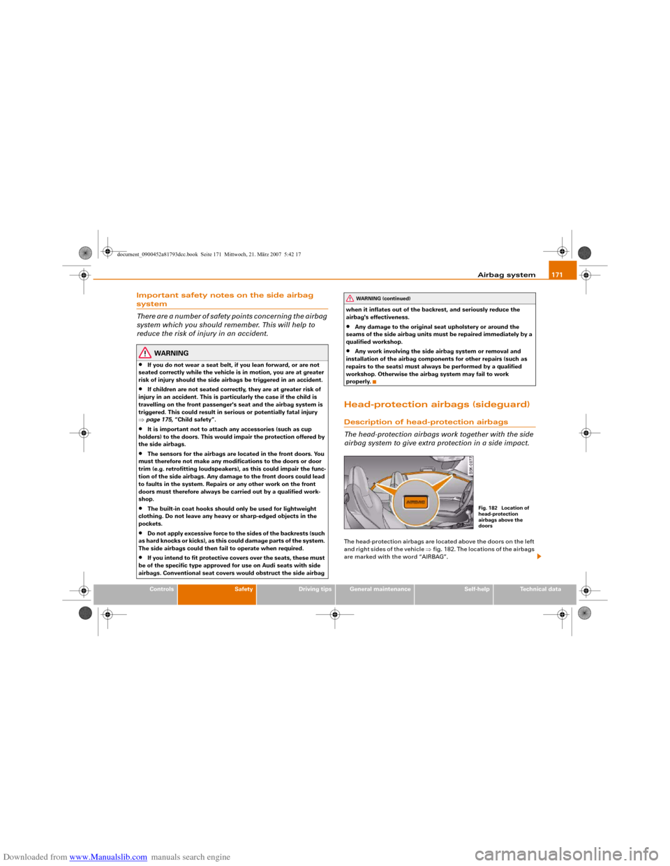
airbag system to give extra protection in a side impact.The head-protection airbags are located above the doors on the left
and right sides of the vehicle ⇒fig. 182. The locations of the airbags
are marked with the word “AIRBAG”.
WARNING (continued)
Fig. 182 Location of
head-protection
airbags above the
doors
document_0900452a81793dcc.book Seite 171 Mittwoch, 21. März 2007 5:42 17
Page 175 of 294
Downloaded from www.Manualslib.com manuals search engine Airbag system173
Controls
Safety
Driving tips
General maintenance
Self-help
Technical data control for the garage door). These objects could cause injury if the
head-protection airbag is triggered.
•
The sensors for the airbags are located in the front doors. You
must therefore not make any modifications to the doors or door
trim (e.g. retrofitting loudspeakers), as this could impair the func-
tion of the side airbags. Any damage to the front doors could lead
to faults in the system. Repairs or any other work on the front
doors must therefore always be carried out by a qualified work-
shop.
•
Where sun blinds are fitted on the rear doors, these must not
obstruct or impair the airbags in any way.
•
If unsuitable accessories are installed near the head-protection
airbag, the protection afforded by the airbag can be seriously
impaired if the system is triggered. When the head-protection
airbag opens, parts of these accessories could be thrown into the
vehicle and injure passengers ⇒page 239.
•
Any work involving the head-protection airbags, or removal
and installation of the airbag components for other repairs (such
as repairs to the roof liner), must always be performed by a quali-
fied workshop. Otherwise the airbag system may fail to work
properly.
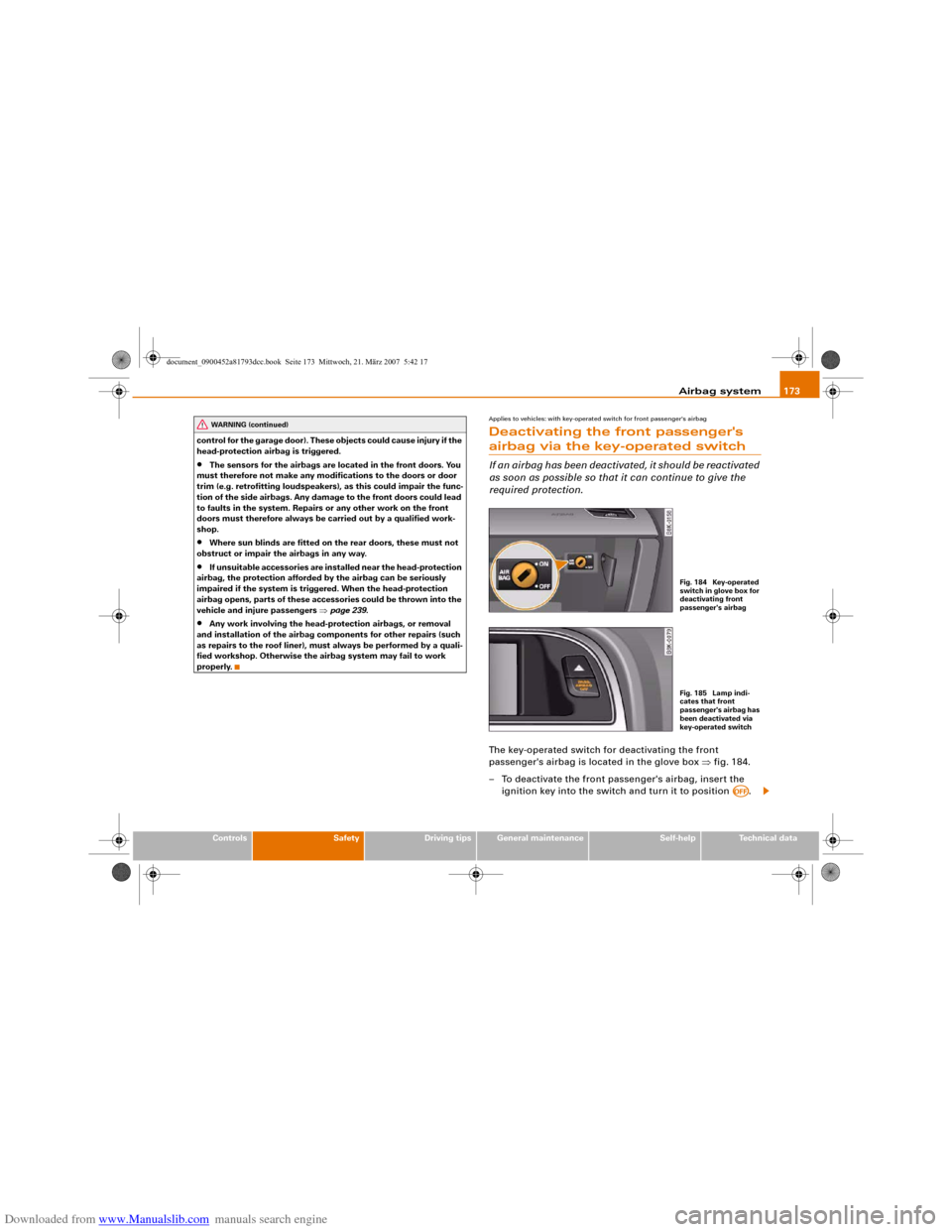
Applies to vehicles: with key-operated switch for front passenger's airbagDeactivating the front passenger's airbag via the key-operated switchIf an airbag has been deactivated, it should be reactivated
as soon as possible so that it can continue to give the
required protection.The key-operated switch for deactivating the front
passenger's airbag is located in the glove box ⇒fig. 184.
– To deactivate the front passenger's airbag, insert the
ignition key into the switch and turn it to position .
WARNING (continued)
Fig. 184 Key-operated
switch in glove box for
deactivating front
passenger's airbagFig. 185 Lamp indi-
cates that front
passenger's airbag has
been deactivated via
key-operated switch
AOFF
document_0900452a81793dcc.book Seite 173 Mittwoch, 21. März 2007 5:42 17
Page 188 of 294
Downloaded from www.Manualslib.com manuals search engine Intelligent technology 186Intelligent technologyElectronic stabilisation program (ESP)General notes
The electronic stabilisation program increases the car's
stability on the road.The ESP is designed to enhance the control over the vehicle in crit-
ical handling situations, such as when accelerating and cornering.
It reduces the tendency to skid under all road conditions and
improves the stability and roadholding of the vehicle. The system
works at all speeds.The anti-lock brake system (ABS), the electronic differential lock
(EDL) and the traction control system (ASR) are all integrated into
the electronic stabilisation program.
How the system works
The ESP control unit processes data from the three integrated
systems. It also processes additional inputs provided by other high-
precision sensors. These register the vehicle's rotation about the
vertical axis (yaw rate), lateral acceleration, brake pressure and
steering wheel angle.
The system uses the steering wheel angle and road speed to calcu-
late the changes of direction intended by the driver, and constantly
compares them with the actual behaviour of the vehicle. If the
desired course is not being maintained (for instance, if the car is
starting to skid), then the ESP compensates automatically by
braking the appropriate wheel.
The forces acting on the braked wheel effectively bring the car back
to a stable condition. If the car is oversteering (rear wheels losing
grip first) the brake application is concentrated on the outside front
wheel; if the car is understeering (front wheels losing grip first), ESP
brakes the inside rear wheel. This automatic brake application is
accompanied by characteristic noises.
The ESP works in conjunction with the ABS ⇒page 187. If a
malfunction should occur in the ABS, the ESP will also be out of
action.
Switching on
The ESP is switched on automatically when the engine is started
and performs a self-test routine. As soon as this routine is complete,
the system switches back to normal operating mode. You can press
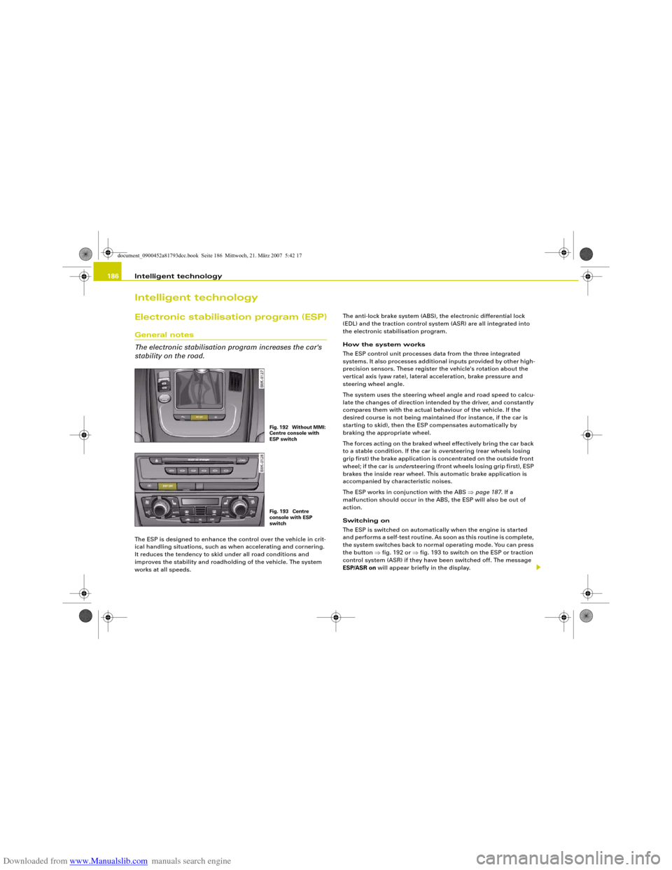
the button ⇒fig. 192 or ⇒fig. 193 to switch on the ESP or traction
control system (ASR) if they have been switched off. The message
ESP/ASR on will appear briefly in the display.
Fig. 192 Without MMI:
Centre console with
ESP switchFig. 193 Centre
console with ESP
switch
document_0900452a81793dcc.book Seite 186 Mittwoch, 21. März 2007 5:42 17