bulb AUDI S6 2009 Owners Manual
[x] Cancel search | Manufacturer: AUDI, Model Year: 2009, Model line: S6, Model: AUDI S6 2009Pages: 398, PDF Size: 43 MB
Page 6 of 398
Table of contents
Weights . . . . . . . . . . . . . . . . . . . . . . . 367
Dimensions . . . . . . . . . . . . . . . . . . . . 368
Data . . . . . . . . . . . . . . . . . . . . . . . . . . . 369
300 hp, 3.0 liter, 6 -cylinder engine 369
255 hp, 3.2 liter, 6 -cy lind er engine 370
350 hp, 8-cylinder engine . . . . . . . 371
Do-it-yourself service ... 34
1 Consumer Information . . . . . . . . . 372
What do I do now? . . . . . . . . . . . . . 342
Trunk escape handle . . . . . . . . . . . . 342
Jack, tools and spare wheel . . . . . . 342
Changing a wheel . . . . . . . . . . . . . . 344
Fuses and bulbs . . . . . . . . . . . . . . . . 351
Fus es . . . . . . . . . . . . . . . . . . . . . . . . . . 351
Bulbs ................... •...... 355
Emergency situations . . . . . . . . . . 357
Genera l . . . . . . . . . . . . . . . . . . . . . . . . 357
Starting by pushing or towing . . . . 357
Starting with jumper cab les . . . . . . 357
Use of juniper cables . . . . . . . . . . . . 358
Em ergency towing with commercia l
tow truck . . . . . . . . . . . . . . . . . . . . . . 360
Lifting vehicle . . . . . . . . . . . . . . . . . . 362
Technical data
General information
Explanation of technical data ... .
Vehicle identification ........... .
Displaying Vehic le Ident ification
Number in the MMI ......... ... . 365
366
366
366
367 Warranty
coverages ........... .
Operating your vehicle outside the
U.S.A. or Canada .............. .
Audi Service Repair Manuals and
Literature ..................... .
Maintenance .............. ... .
Additional accessories, modifications and parts
rep lacement .................. .
Dec laration of Compliance,
Telecommunications and Electron ic
Systems .................. .... . 372
372
372
372
374
375
Alphabetical index
. . . . . . 379
Page 25 of 398
Driver information display
Introduction
General notes
The driver information display inside the instrument
cluster provides you, the driver, with much useful infor
mation.
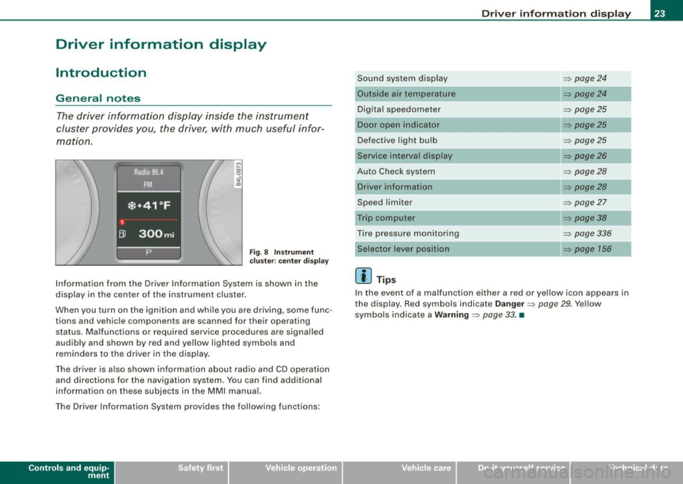
F ig. 8 Inst rume nt
c luster: ce nte r display
Information from the Driver Information System is shown in the
display in the center of the instrument cluster.
When you turn on the ignition and whi le you are driving, some func
tions and vehicle components are scanned for their operating status . Malfunctions or required service procedures are signa lled
audibly and shown by red and yellow lighted symbols and
reminders to the driver in the display .
The driver is also shown information about radio and CD operation and directions for the navigation system . You can find additional
information on these subjects in the MMI manual.
The Driver Information System provides the following functions:
Con tro ls and eq uip
ment
Dri ver inf orm atio n di spl ay
Sound system disp lay ~ page24
Outside air temperature ~ pa ge24
Digita l speedometer ~ page25
Door open in dicator ~ p age25
Defective light bulb ~ page25
Service interval display ~ page26
Auto Check system ~ page28
Driver inform ation ~ pa ge28
Speed limiter ~ page27
Tr ip computer ~ pag e38
Tire pressure monitoring ~ page336
~ page 156
[ i ] Tip s
In the event of a malfunction either a red or yellow icon appears in
the display. Red symbols indicate
D ange r~ page 29 . Yellow
symbols indicate a
W arning ~ page 33 . •
Vehicle care I I irechnical data
Page 27 of 398
Digital speedometer
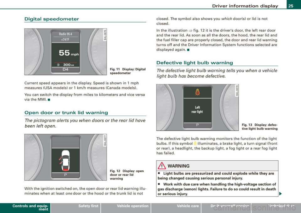
Fig. 11 Display: Digital
speedometer
Current speed appears in the display . Speed is shown in 1 mph
measures (USA models) or 1 km/h measures (Canada models).
You can switch the display from miles to kilometers and vice versa
via the MMI. •
Open door or trunk lid warning
The pictogram alerts you when doors or the rear lid have
been left open.
Fig . 12 Display: open
door or rear
lid
warning
With the ignition switched on, the open door or rear lid warning illu
minates when at least
one door or the hood or the trunk lid is not
Con tro ls and eq uip
ment
Driver information display
closed. The symbol also shows you which door(s) or lid is not
closed.
In the illustration=> fig. 12 it is the driver's door, the left rear door
and the rear lid. As soon as all the doors, the hood, the rear lid and
the fuel filler cap are properly closed, the door and rear lid warning
turns off and the Driver Information System functions selected are
displayed again .•
Defective light bulb warning
The defective light bulb warning tells you when a vehicle
light bulb has become defective.
Fig. 13 Display: defec
tive light bulb warning
The defective light bulb warning monitors the function of the light
bulbs . If this symbol illuminates, a brake light, a turn signal (front
or rear), a headlight, the backup light, a fog light or a rear fog light
has failed.
& WARNING
• Light bulbs are pressurized and could explode while they are
being changed causing serious personal injury.
• Work with due care when handling the high-voltage section of
gas discharge (xenon) lights. Failure to do so could result in death
or serious injury . ..,
Vehicle care I I Technical data
Page 28 of 398
Driver information display
[ i J Tips
Have the bulb replaced or the connection repaired by your autho
rized Audi Service department. •
Service interval display
The service interval display reminds you when your next
service is due.
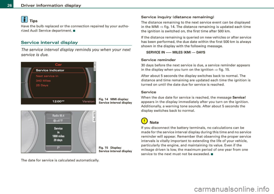
Fig . 14 MMI display:
Service interval display
Fig. 15 Display:
Service interval display
The date for service is calculated automatically.
Service inquiry (distance remaining)
The distance remaining to the next service event can be displayed
in the MMI
~ fig. 14 . The distance remaining is updated each time
the ignition is switched on, the first time after 500 km.
If the distance remaining is queried on new vehicles or after service
has been performed, the due date within the first 500 km is always
shown in the display with the following message.
SERVICE IN ····• MILES (KM) ··• DAYS
Service reminder
30 days before the next service is due, a service reminder appears
in the display when you turn on the ignition ::> fig. 15.
After about 5 seconds the display switches back to normal. The distance and time remaining are updated each time the ignition is
turned on until the date due for service is reached.
Service
When the due date for service is reached, the message Service!
appears in the display immediately after you turn on the ignition.
Additionally, a warning tone sounds. After about 5 seconds the
display switches back to normal.
0 Note
I f you disconnect the battery terminals, no calculations can be
made for the service interval display during this time and no service
reminder will appear. Remember that observing the proper service
intervals is vitally important to extending the life of your vehicle,
particularly the engine, and maintaining its value. Even if the
mileage driven is low, the maximum period of one year from one
service to the next must not be exceeded. •
Page 35 of 398
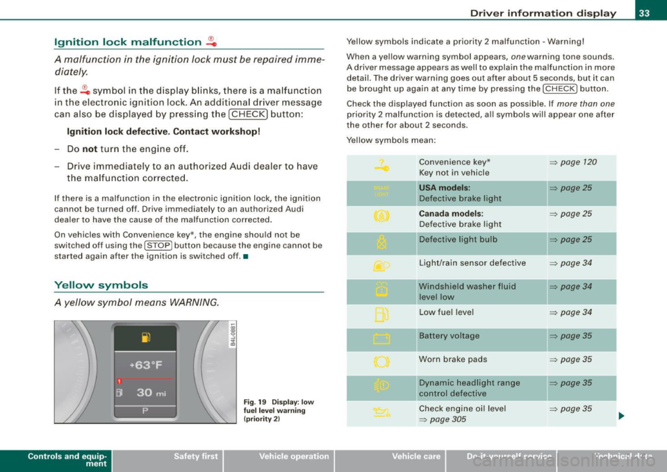
Ignition lock malfunction ~
A malfunction in the ignition Jock must be repaired immediately.
If the ~ symbol in the display blinks, there is a malfunction
in the electronic ignition lock. An additional driver message
can also be displayed by press ing the [CHECK] button:
Ign iti on lock defe ctive . C ont ac t wo rkshop !
- Do not turn the engine off.
- Drive immediately to an auth orized A udi dealer to have
the malfunction corrected .
If there is a malfunction in the electronic ignition lock, the ignition
cannot be turned off . Drive immediately to an authorized Audi
dea ler to have the cause of the malfunction corrected .
On vehicles with Convenience key*, the engine should not be
switched off using the [
STOP] button because the engine cannot be
started again after the ignition is switched off. •
Yellow symbols
A yellow symbol means WARNING.
Contro ls and eq uip
ment
Fig . 19 Dis pl ay: low
fu el le ve l wa rning
(pr io rity 2)
Dri ver inf orm atio n di spl ay
Ye llow symbols indicate a priority 2 malfunction -Warning!
When a yellow warning symbol appears,
one warning tone sounds.
A driver message appears as well to explain the malfunction in more detail. The driver warning goes out after about 5 seconds, but it can
be brought up again at any time by pressing the [ CHECK
I button .
Check the displayed function as soon as possible . If
more than one
priority 2 malfunction is detected , a ll symbols will appear one after
the other for about 2 seconds.
Yellow symbols mean:
Convenience key*
~ page 120
Key not in vehicle
USA models: ~ page25
Defective brake light
Canad a mod els: ~ page25
Defective brake light
11 Defective light bulb
~ page25
-
Light/rain sensor defective ~ page34
Windshield washer fluid ~ page34
level low
Low fuel leve l
~ page34
Battery voltage ~ page35
Worn brake pads ~ page35
IIDynamic headlight range ~ page35
control defective
-
Check engine oi l level ~ page35
~ page305 ...
Vehicle care I I irechnical data
Page 68 of 398
![AUDI S6 2009 Owners Manual Clear vision
[ i] Tips
With the switch in AUTO front fog lights and rear fog lights cannot
be turned on in addition. •
Applies to vehic les: with Adapt ive Light
Adaptive Light AUDI S6 2009 Owners Manual Clear vision
[ i] Tips
With the switch in AUTO front fog lights and rear fog lights cannot
be turned on in addition. •
Applies to vehic les: with Adapt ive Light
Adaptive Light](/img/6/57595/w960_57595-67.png)
Clear vision
[ i] Tips
With the switch in AUTO front fog lights and rear fog lights cannot
be turned on in addition. •
Applies to vehic les: with Adapt ive Light
Adaptive Light
When making a turn or driving around tight corners, the
relevant area of the road is better illuminated.
Adaptive Light (making turns)
Fig. 55 Adaptive Light
when turning and driving through curves
An additional bulb in the headlight provides a cornering light@ in
addition to the low beam@:::::, fig. 55. Adaptive Light is switched on
and off automatically depending on driving conditions .
When you activate the turn signal lever, the Adaptive Light for the
same side is switched on. Please note that the turn signal lever must
engage.
Adaptive Light is not switched on if you only move the turn signal
lever to the point of resistance to signal a lane change :::::,
page 67,
"Turn signal ¢i ¢ and high beam lsD lever".
When driving around bends, Adaptive Light is controlled according
to steering wheel angle. • It is switched on in tight corners. • It
is not switched on in long, open bends .
Adaptive Light (in curves)
When driving through curves, the low beams © are automatically
controlled depending on driving speed and the steering wheel
angle.
The two main beams pivot at different angles so that there is no
unilluminated area in front of the vehicle.
[ i] Tips
• The system works up to a speed of about 43 mph (70 km/h). If the
speed is higher, it is not activated.
• Adaptive Light (in curves) functions at a speed of about 6 mph
(10 km/h) and is deactivated at speeds below about 4 mph
(6 km/h). •
Applies to vehi cles: with light pac kage
Perimeter lighting in the mirror housing
LEDs in the exterior mirror housing illuminate the ground
during entry.
This function ensures that when unlocking, the vehicle periphery is
illuminated in the dark. LEDs in the exterior mirror housing are
switched on. The function cannot be turned off separately. •
Page 315 of 398
__________________________________________ C_ h _ e_c _k _in _ g =- a_ n __ df _i_ lli _n ___ g __ fflllll
•
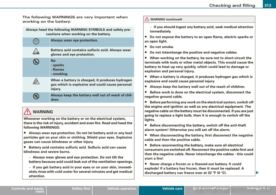
The following WARNINGS are very important when
working on the battery:
Always heed the following WARNING SYMBOLS and safety pre
cautions when working on the battery .
Always wear eye protection.
Battery acid contains sulfuric acid. Always wear
gloves and eye protection.
No
- sparks
- flames
- smoking.
When a battery is charged, it produces hydrogen
gas which is explosive and could cause personal
injury.
Always keep the battery well out of reach of chil
dren.
& WARNING
Whenever working on the battery or on the electrical system,
there is the risk of injury, accident and even fire. Read and heed the
following WARNINGS:
• Always wear eye protection. Do not let battery acid or any lead
particles get on your skin or clothing. Shield your eyes. Explosive
gases can cause blindness or other injury.
• Battery acid contains sulfuric acid. Sulfuric acid can cause
blindness and severe burns.
- Always wear gloves and eye protection. Do not tilt the
battery because acid could leak out of the ventilation openings.
- If you get battery acid in your eyes or on your skin, immedi
ately rinse with cold water for several minutes and get medical
attention.
& WARNING (continued)
-If you should ingest any battery acid, seek medical attention
immediately.
• Do not expose the battery to an open flame, electric sparks or
an open light.
• Do not smoke.
• Do not interchange the positive and negative cables .
• When working on the battery, be sure not to short -circuit the
terminals with tools or other metal objects. This would cause the battery to heat up very quickly, which could lead to damage or
explosion and personal injury.
• When a battery is charged, it produces hydrogen gas which is
explosive and could cause personal injury.
• Always keep the battery well out of the reach of children.
• Before work is done on the electrical system, disconnect the
negative ground cable.
• Before performing any work on the electrical system, switch off
the engine and ignition as well as any electrical equipment. The
negative cable on the battery must be disconnected.
If you are just
going to replace a light bulb, then it is enough to switch off the
lights.
• Before disconnecting the battery, switch off the anti-theft
alarm system! Otherwise you will set off the alarm.
• When disconnecting the battery, first disconnect the negative
cable and then the positive cable.
• Before reconnecting the battery, make sure all electrical
consumers are switched off. Reconnect the positive cable first and
then the negative cable . Never interchange the cables - this could
start a fire!
• Never charge a frozen or a thawed-out battery. It could
explode! If a battery has frozen, then it must be replaced. A
discharged battery can freeze over at 32 °F (0 °CI. .,,_
Vehicle care
I t •
Page 353 of 398
Fuses and bul bs -
------------------
Fuses and bulbs
Fuses
Replacing a fuse
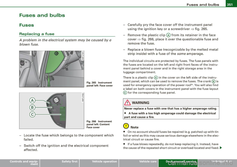
A problem in the electrical system may be caused by a
blown fuse.
Fig . 2 65 Instru ment
pa nel left: Face c over
F ig . 266 I nst ru me nt
pa nel left: Co ntent
F ac e cover
- Locate the fuse which belongs to the component which
failed.
- Switch off the ignition and the e lectr ica l component
affected. - Care
fully p ry t he face cover off the instr umen t pane l
using the ignition key or a screwdriver~ fig. 265.
- Rem ove the plastic clip @ from i ts retainer in the face
cove r~ fig. 266, place i t over the questionable fuse and
remove the fuse.
- Replace a blow n fuse (recogniza ble by the melted metal
str ip inside) wi th a f use of the
same amperage.
The individual circuits are protected by fuses. T he fuse panels with
the fuses are located on the left and right front faces of the instru
ment pane l behind a cover and in the right storage area in the
luggage compartment.
There is a plastic clip @ in the cover on the lef t side of the instru
ment pane l, which can be used to remove the fuses. The crank © is
used for emergency operation of the power roof*. You will also find
a label on both covers in the instrument panel with the fuse layout
© for the corresponding fuse panel.
& WARNING
Nev er replac e a fuse with on e that ha s a high er amperag e rating .
• A fu se w ith a t oo high ampe rage could damage the ele ctr ical
pa rt a nd cause a fire .
0 Note
• On no account should fuses be repaired (e .g. patched up wi th tin
foil or wire) as this may cause serious damage elsewhere in the e lec
trica l circuit o r cause fire.
• I f a fuse blows repeatedly, do not keep replacing it. Instead, have
the cause of the repea ted short circuit or overload located and fixed.
ti>
Vehicle care Do-it-yourself service Technical data
Page 354 of 398
-Fuses and bulbs Pffl..._ _____________________ _
[ i J Tip s
You are wel l advised to keep a supply of spare fuses in your vehicle .
Fuses with the proper ampere ratings are availab le at your Audi
dea ler. •
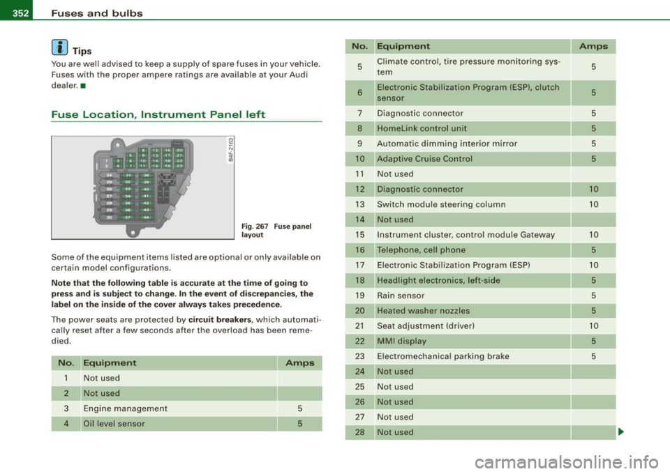
Fuse Location , Instrument Panel left
Fig . 267 Fuse pa nel
l ayo ut
Some of the equipment items listed are optional or only ava ilable on
certain model configurations .
Note th at t he fo llo wi ng t able i s acc urat e at th e time of goin g to
pr ess and is subject t o ch ang e. In th e eve nt of d iscrep ancie s, th e
labe l on th e in side of th e cover always ta kes prece de nce .
The power seats are protected by cir cuit br eaker s, which automati
cally reset after a few seconds after the overload has been reme
died.
N o. Equipm ent
1 Not used
2
3
4
Not used
Engine management
Oil level sensor Amps
5
5
No
.
5
6
..
7
8
9
10
1 1
12
13
14
15
16
17
18
19
20
21
22
23
24
25
26
27
28
Equipm ent
Climate cont rol , tire pressure monitoring sys
tem
Electronic Stabilization Program (ESP), clutch
sensor
Diagnostic connector
Homelink control unit
Automa tic dimming interior mirror
Adaptive Cruise Control
Not used
Diagnostic connector
Switch modu le steering column
Not used
I nstrument c luster, control module Ga teway
Telephone, cell phone E lectronic Stabilization Program (ESP)
Headlight electronics, left -side
Rain sensor
Heated washer nozzles
Seat adjustment (driver)
MMI display
E lectromechanica l parking brake
Not used
Not used
Not used
N ot used
Not used Amps
5
5
5
5
5
5
10
10
10
5
10
5
5
5
10
5
5
-
Page 356 of 398
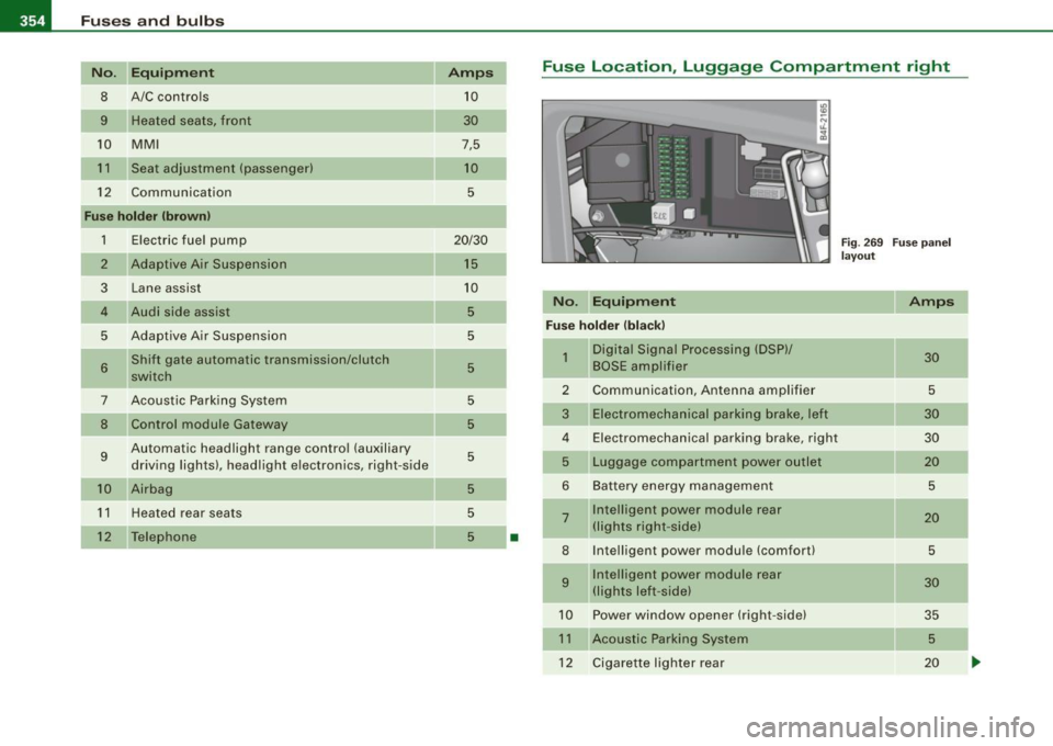
IIJII Fuses and bulbs ..._ ____ .;__...;_;,;_ _______________________________ _
No. Equipment
8 A/C controls
9 Heated seats, front
10 MMI
11 Seat adjustment (passenger)
12 Communication
Fuse holder (brown)
1
2
3
4
5
6
7
8
9
10
11
12
Electric fuel pump
Adaptive Air Suspension Lane assist
Audi side assist
Adaptive Air Suspension Shift gate automatic transmission/clutch
switch
Acoustic Parking System Control module Gateway
Automatic headlight range control (auxiliary driving lights), headlight electronics, right-side
Airbag
Heated rear seats
Telephone Amps
10
30
7,5
10
5
20/30
15
10
5
5
5
-
5
5
5
5
5
5
•
Fuse Location, Luggage Compartment right
Fig. 269 Fuse panel
layout
No. Equipment Amps
Fuse holder (black)
-
1 Digital Signal Processing (DSP)/ 30 BOSE ampl ifier
2 Communication, Antenna amplifier 5
3
Electromechanical parking brake, left 30
4 Electromechanical parking brake, right 30
5
Luggage compartment power outlet 20
6 Battery energy management 5
7 Intelligent power module rear 20 (lights right -side)
8 Intelligent power module (comfort) 5
9 Intelligent power module rear 30 (lights left -side)
10 Powe r window opener (right-side) 35
11
Acoustic Parking System 5
12 Cigarette lighter rear 20