power steering AUDI S8 2009 Owners Manual
[x] Cancel search | Manufacturer: AUDI, Model Year: 2009, Model line: S8, Model: AUDI S8 2009Pages: 408, PDF Size: 91.63 MB
Page 13 of 408
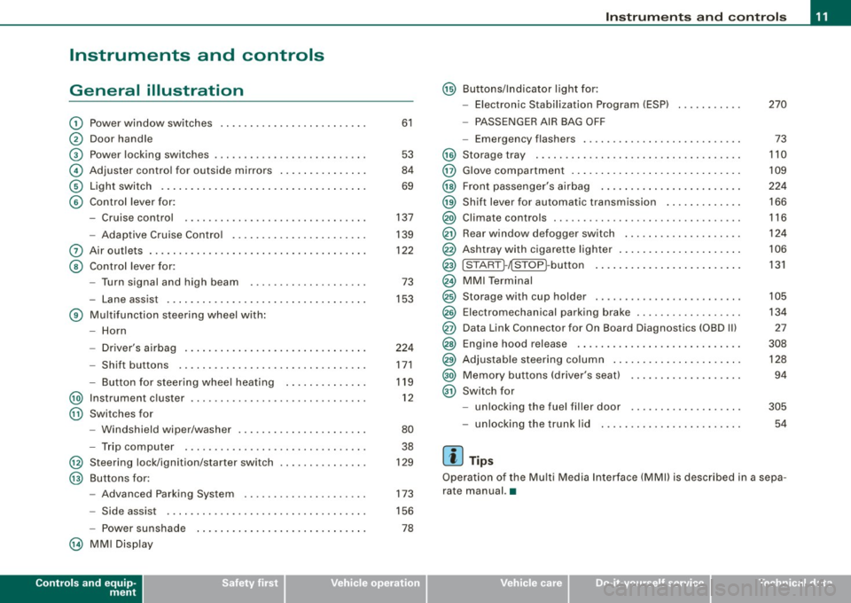
Instruments and controls
General illustration
G) Power window switches .. ...... .... ... .. ....... .
0 Door handle
G) Pow er locking switches ... .... .... .... ... ....... .
© Adjuster control for outside mirrors ............. . .
© Light switch .... .... ....... ... ... .. .... .. ..... .
© Control lever for:
- Cruise control .... .... ... .... .... .... ... .... .
- Adaptive Cruise Control .. ... ....... .......... .
0 Air outlets ...... .............................. .
@ Control lever for:
- Turn signal and high beam ....... ... .... ..... .
- Lane assist .. .... ..................... ... ... .
® Multifunction steering wheel with :
- Horn
- Driver's airbag .. ...... ...... ....... ...... ... .
- Shift buttons ........... .... ... .. .... .... ... .
Button for steering wheel heating ..... .. .. .... .
@ Instrument cluster .................... .... ..... .
@ Swi tches for
- Windshield wip er/ washer ............. ... .. ... .
- Trip computer ..... ... ... .... .... ... ... ... .. .
@ Steering lock/ignition /starter switch
@ Buttons for :
- Advanced Parking System .. .... .... .... .... .. .
- Side assist ..... .. .. ... ..... .... ... .. .... ... .
- Power sunshade
@ MMI Display
Controls and equip
ment
61
53
84
69
137
139
122 73
153
224 171
119 12
80 38
129
173
156
78
Instruments and controls
@ Buttons/Indicator light for:
- Electronic Stabilization Program (ESP) 270
- PASSENGER AIR BAG OFF
- Emergency flashers . . . . . . . . . . . . . . . . . . . . . . . . . . . 73
@ Storage tray . . . . . . . . . . . . . . . . . . . . . . . . . . . . . . . . . . . 110
@ Glove compartment . . . . . . . . . . . . . . . . . . . . . . . . . . . . . 109
@ Front passenger's airbag . . . . . . . . . . . . . . . . . . . . . . . . 224
@) Shift lever for automatic transmission . . . . . . . . . . . . . 166
@ Climate controls . . . . . . . . . . . . . . . . . . . . . . . . . . . . . . . . 116
@ Rear window d efogger switch . . . . . . . . . . . . . . . . . . . . 124
@ Ashtray with cigarette lighter . . . . . . . . . . . . . . . . . . . . . 106
@ ISTART ]-~STOP ~button . . . . . . . . . . . . . . . . . . . . . . . . . 131
@ MMI Terminal
@ Storage w ith cup holder . . . . . . . . . . . . . . . . . . . . . . . . . 105
@ Electromechanical parking brake . . . . . . . . . . . . . . . . . . 134
@ Data Link Connector for On Board Diagnostics (OBD Ill 27
@ Engine hood release . . . . . . . . . . . . . . . . . . . . . . . . . . . . 308
@ Adjustable steering column . . . . . . . . . . . . . . . . . . . . . . 128
@) Memory buttons (driver's seat) . . . . . . . . . . . . . . . . . . . 94
@ Switch for
- unlocking the fuel filler door . . . . . . . . . . . . . . . . . . . 305
- unlocking the trunk lid 54
[ i ] Tips
Operation of the Multi Media Interface (MMI) is described in a sepa
rate manual. •
I • •
Page 131 of 408
___________________________________________________ O_ n_ t_h _e_ r_o _a_ d _ ___.9I
& WARNING !continued)
injuries to the hands, arms and head if the driver's airbag
deploys. •
Easy entry feature
The easy entry feature makes it easier to enter and exit the
vehicle by automatically adjusting the steering wheel.
Press the button @ :::> page 128, fig. 143 to turn the easy
entry feature on or off.
When the easy entry feature is turned on (button depressed), the
steering wheel moves up to the parked position when the ignition is
turned off. After you enter the vehicle, the steering wheel moves to
the stored position as soon as you turn on the ignition. •
Ignition lock and ignition switch
Ignition key positions
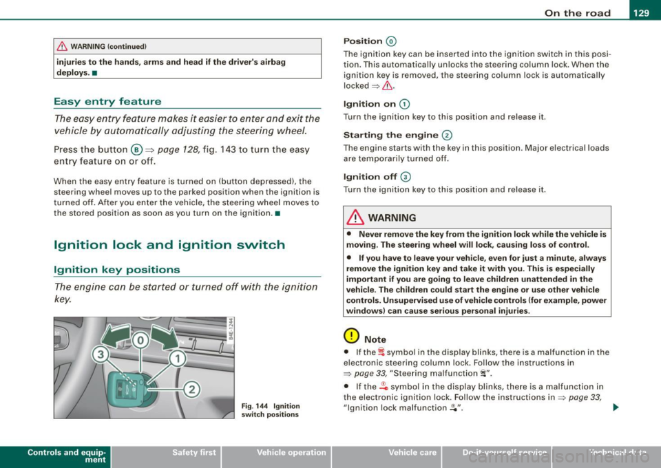
The engine can be started or turned off with the ignition
key.
Con tro ls and eq uip
ment
Fig . 144 Ignition
switch positions
Position @
The ignition key can be inserted into the ignition switch in this posi
tion. This automatically unlocks the steering column lock. When the
ignition key is removed, the steering column lock is automatically
locked=> &.
Ignition on G)
Turn the ignition key to this position and release it.
Starting the engine @
The engine starts with the key in this position. Major electrical loads
are temporarily turned off.
Ignition off G)
Turn the ignition key to this position and release it.
& WARNING
• Never remove the key from the ignition lock while the vehicle is
moving. The steering wheel will lock, causing loss of control.
• If you have to leave your vehicle, even for just a minute, always
remove the ignition key and take it with you. This is especially
important if you are going to leave children unattended in the
vehicle. The children could start the engine or use other vehicle
controls. Unsupervised use of vehicle controls (for example, power
windows) can cause serious personal injuries.
0 Note
• If the ~ symbol in the display blinks, there is a malfunction in the
electronic steering column lock. Follow the instructions in
=>
page 33, "Steering malfunction i".
• If the .Pc, symbol in the display blinks, there is a malfunction in
the electronic ignition lock. Follow the instructions in
=> page 33,
"Ignition lock malfunction .Pe". ..,.
Vehicle care I I irechnical data
Page 141 of 408
__________________________________________ ...;A~d~a~p~t~iv~e~C~ru~is~e~C:_:o~n~t!..ro~I _J __
Adaptive Cruise Control
Speed and distance control system
Applies to vehic les : with Adaptive C ruise Cont rol
Description
The Adaptive Cruise Control driver assistance program is
a combined speed and distance control system.
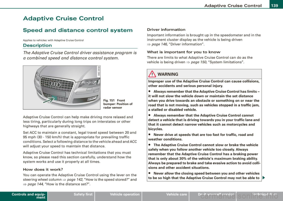
Fig. 151 Front
bumper: Position of
radar sensor
Adaptive Cruise Control can help make driving more relaxed and
less tiring, particularly during long trips on interstates or other
highways that are generally straight .
Set ACC to maintain a constant, legal travel speed between 20 and
95 mph (30 -150 km/h) that is appropriate for prevailing traffic
conditions. Select a following distance to the vehicle ahead and ACC
will adjust your speed to maintain that distance .
Adaptive Cruise Contro l has technical limitations that you must
know, so please read this section carefully, understand how the
system works and use it proper ly at all times .
How does it work?
You can operate the Adaptive Cruise Control using the lever on the
steering wheel column =>
page 142, "How is the speed stored?" and
=>
page 144, "How is the distance set?" .
Contro ls and eq uip
ment
Driver information
Important information is brought up in the speedometer and in the
instrument cluster display as the vehicle is being driven
=> page 146, "Driver information" .
What is important for you to know
There are limits to what Adaptive Cruise Control can do as the
vehicle is being driven =>
page 150, "System limitations" .
& WARNING
Improper use of the Adaptive Cruise Control can cause collisions,
other accidents and serious personal injury.
• Always remember that the Adaptive Cruise Control has limits -
it will not slow the vehicle down or maintain the set distance
when you drive towards an obstacle or something on or near the
road that is not moving, such as vehicles stopped in a traffic jam,
a stalled or disabled vehicle.
• Always remember that the Adaptive Cruise Control cannot
detect a vehicle that is driving towards you in your traffic lane and
that it cannot detect narrow vehicles such as motorcycles and
bicycles .
• Never drive at speeds that are too fast for traffic, road and
weather conditions .
• The Adaptive Cruise Control cannot slow or brake the vehicle
safely when you follow another vehicle too closely. Always
remember that the Adaptive Cruise Control has a braking power
that is only about 30% of the vehicle 's maximum braking ability.
Always be prepared to brake and take evasive action to avoid colli
sions and other accident situations.
• Never allow the closing speed between you and other vehicles
to be so high that the Adaptive Cruise Control may not be able to _,,,
Vehicle care I I irechnical data
Page 173 of 408
Automatic transmi ssio n -
------------------'
Applies to vehi cles : wi th tip troni c-st eerin g wh eel
Steering wheel with tiptronic ®
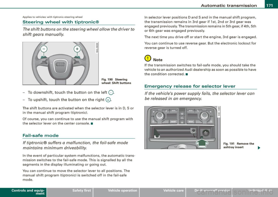
The shift buttons on the steering wheel allow the driver to
shift gears manually.
F ig . 190 Steering
whee l: S hift butt ons
- To downshift, touch the button on the left Q .
- To upshift , touch the button on t he right G) .
The shift buttons are activated when the selector lever is in D, Sor
in the manual shift program (tip tronic) .
Of course, you can continue to use the manual shift program with
the selector lever on the center console .•
Fail-safe mode
If tiptronic® suffers a malfunction, the fail-safe mode
maintains minimum driveability.
In the event of particular system malfunctions, the automatic trans
mission switches to the fail -safe mode. This is s ignalled by all the
segments in the display illuminating or going out .
You can continue to move the selector lever to all positions. The manual shift program (tiptronic) is switched off in the fail-safe
mode .
Contro ls and eq uip
ment
In selector lever positions D and Sand in the manual shift program ,
the transmission remains in 3rd gear if 1st, 2nd or 3rd gear was engaged previous ly. The transmission remains in 5th gear, if 4th, 5th
or 6th gear was engaged previously .
The next time you drive off or start the engine, 3rd gear is engaged .
You can continue to use reverse gear . But the electronic lockout for
reverse gear is turned off .
0 Note
If the transmission switches to fail -safe mode, you should take the
vehicle to an au thori zed Audi dea lership as soon as possib le to have
t he condition corrected .•
Emergency release for selector lever
If the vehicle's power supply fails, the selector lever can
be released in an emergency.
Fig . 19 1 Rem ove th e
as htray i nser t
~
Vehicle care I I Technical data
Page 273 of 408
The direction in which the driver wishes to travel is determined with
t he aid of the steering angle and vehicle speed and is continua lly
compared with the actual behavior of the vehicle. If the two do not
match, for example, when the vehic le starts hydrop laning on a wet
road, ESP will automatically brake the appropriate whee l to correct
the prob lem.
The vehicle is then stab ilized by the forces acting on the whee l
during braking. If the vehicle is oversteering (rear tends to skid out
of the turn), the brakes are mainly app lied on the wheel that is on
the outside of the curve. In the case of a vehicle that is understeering
(tendency to sl ide out of the curve), the brakes are applied at the
rear wheel that is on the inside of the curve . An acoustic signal indi
cates when ESP brake application cuts in
~ & .
The system operates across the entire speed range in combination
with the ABS system
~ page 274 . If the Anti -Lock Brake System
(ABS) malfunctions, the ESP wi ll be out of action as well.
Ac tivat ion
When you turn on the eng ine, ESP will automatically be activated
and will perform a self -test.
The system can be activated or deactiva ted by pressing the button
~ page 270, fig. 256. The warning light comes on when the system
is switched off
~ page 18.
Normally , the ESP should always be on, however, it may be advanta
geous to turn off the system in certain special cases when some
degree of wheel spin is desired such as :
• when driving with snow chains
• when driving in deep snow or on a loose surface (to allow the
wheels to dig in to reach firm ground)
• when trying to "rock" the vehicle free when it has beco me stuck.
T he system should be reactivated once you are no longer in such
situations .
Both the ABS and EDS systems are still functioning even if the ESP
is switched off .
Controls and equip
ment Safety first Vehicle operation
In
te llig ent tec hn olo gy
& WARNING
The Ele ctron ic St abiliz ation Progr am i s ne ve rt h el ess s ubject to the
laws of ph ysics. It i s particularl y important t o pay attention t o th is
f ac t on wet an d slipp ery road s. It i s th ere fore important that you
alway s adapt your driving to the condition of the road and traffic
c onditio ns. Do n ot allow the in crease d sa fety p ro vi ded by t he El ec
tronic Stabiliz ation Program sy stem to lu ll you into a ccepting
a dditional safety ri sk s.
c
Electronic differential lock (EDL)
The electronic differential lock monitors the rotation al
s p eed of the drive wheels.
G en era l not es
The elect ronic differential lock (EDU helps the car to start moving,
accelerate and c limb a gradient on surfaces providing poor or
a lmost no grip . Without EDL , this would be difficult, if not impos
s ib le.
How the system works
The EDL operates automatical ly. It monitors the rotational speed of
the drive wheels on an axle with the he lp of the ABS sensors
~ page 274. If a noticeable difference in rotational speed between
the drive wheels on one axle is detected (e.g. on slippery ground on
one side), the spinning w heel is braked, thereby transferring power
to the other drive wheel or wheels (all -whee l drivel. This is done up
to a speed of about 60 mph (100 km/h) . Noises from the brake
system signal that wheel spin is being control led .
Dri ving off
When driving off, always be sur e to ke ep road conditions in mind as
you accelerate. I f one drive wheel spins because it is on a surface
with less grip, gradual ly increase the pressure on the accelera tor
pedal unt il the car star ts to
move . The whee l less able to t ra nsfer
power spins. _.,
Vehicle care Do-it-yourself service Technical data
Page 277 of 408
until the vehicle has braked to the required speed. The brake assis
tant switches itself off as soon as you release the brake pedal.
The brake assistant will not be operative if there is a malfunction in
the ABS.
& WARNING
Please remember that the accident risk always increases if you
drive too fast, especially in corners or on a slippery road, or if you
follow the vehicle ahead of you too closely. Increased risk of an
accident cannot be compensated for even by the brake assistant,
so always maintain a safe speed. •
Servotronic® -advanced power
steering system
The power steering systems uses the power of the
running engine to allow precise steering with little effort.
The advanced Servotronic ® power steering system senses the road
speed and electronically adjusts power assistance to provide
comfortable and safe steering response exactly matched to the
vehicle speed.
Power steering will not work if the engine is off. As a result, the
steering whee l wil l be hard to turn.
The power steering fluid level is checked during the scheduled
maintenance services.
0 Note
If there is an electronic malfunction, servotronic will sti ll function
like a conventional power steering system, providing a constant
steering support force that is no longer proportionate to the vehicle
speed. This is most noticeable when turning the steering whee l at
Controls and equip
ment Safety first Vehicle operation
Intelligent technology
low speeds (for examp
le when parking), -more effort will be
requ ired than usual.
• Be aware of the different than usual steering response and
adjust your steering force accordingly .
• Have the problem checked and set right by an Audi dealer as
soon as possible.
[ i ] Tips
• When the engine is running, never hold the steering whee l
turned all the way to the right or to the left for longer than 15
seconds. The power steering pump will overheat the hydraulic fluid
if you keep holding the steering whee l turned a ll the way. This is
likely to damage the power steering system.
• If the power steering system shou ld fail entire ly, or if the engine
is not running (for examp le, while being towed), you will still be able
to steer the vehicle . However,
considerably more effort will be
required to do so.
• If the power steering system shou ld have a leak, or is not func
t ioning properly, contact your authorized Audi dealer immediately.
• The power steering system requires a special ly formulated
hydraulic fluid. The power steering reservoir is the one located most
forward on the left side of the engine compartment=>
page 310. The
correct fluid level in the reservoir is important for proper func
tioning of the power steering .•
Driving with your q attro®
With All Wheel Drive, all four wheels are driven.
General information
With All Whee l Drive, power is distributed to all four wheels. This
happens automatically depending on your dr iving style and the
road conditions at the time. See also=>
page 271, "Electronic differ
entia l lock (EDU".
Vehicle care Do-it-yourself service Technical data
Page 329 of 408
________________________________________________ T_ i _r_e _s_ a_n_ d_ w_ h_ e_e _ l_s __ ,n
•
& W ARNING (continu ed )
crashes and serious personal in jur ies . Have worn or da maged t ires
replaced immediately .
• Tires age even if they are not being u sed and can fail suddenly ,
especially at high speeds. T ires that are more than 6 years old can
only be used in an emergency and then w ith special care and at
low speed.
Glossary of tire and loading terminology
Accessory weight
means the co mbined we ig ht ( in excess o f those sta nda rd items
which may be rep laced) of automatic transmission, power steering,
power brakes, power w indows, powe r seats, rad io, a nd heater, to
the extent that these items are avai lab le as factory-installed equip
m ent (w hether insta lled or not).
Aspect ratio means t he ratio o f th e height to t he w idt h of the tire in perce nt.
N umbers of 55 or lower indicate a low sidewa ll for improved
steer ing respo nse and b ette r overall ha ndl ing on dry pave ment.
Bead
means the part of the tire that is made of stee l wires, wrapped or
reinforced by ply cords and that is shaped to fit the rim.
Bead separation
means a breakdow n of the bond be tween co mponents i n the bead.
Cord
m eans the strands fo rmi ng the plies in the ti re.
& W ARNING (continued )
• Never mount used tires on your vehicle if you are not sure of
their "previous history. " Old used t ire s may ha ve been damaged
even though the damage cannot be seen that can lead to sudden
tire failure and lo ss of vehicle control.
• If you noti ce unusual vibration or if the vehicle pulls to one side
when driving , always stop as soon as it is safe to do so and check
the wheels and tires for damage . •
Cold tire inflation pressure
mea ns t he ti re pressure reco mm ended by the ve hicle ma nufacturer
for a tire of a designated size that has not been d riven for more tha n
a cou ple o f miles (k ilometers) at low speeds in t he t hre e ho ur per iod
before the tire pressure is measured or ad justed .
Curb weight
means the weight of a moto r vehic le with standard equipment
i nc lud ing the max imu m capac ity o f fue l, o il, and coola nt, a ir c ond i
tioning and additiona l weight of optional equipment.
Extra load tire
means a tire des ign to operate at higher loads and at highe r infla
tion pressures than the corresponding standard tire. Extra load tires
may be identified as "XL", "xi", "EXTRA LOAD", or "RF" on the side
wa ll.
Gross Axle Weight Rating ("GAWR ")
means the load -carrying capacity of a sing le ax le system, measured
at the ti re -ground interfaces.
Gross Vehicle Weight Rating ("GVWR "l
mea ns the ma ximum tot al l oade d weigh t of the vehicle.
Vehicle care
I t •
Page 363 of 408
_________________________________________________ F_ u_ s_ e_s _ a_n _d_ b_ u _ lb_ s _ __._
[ i J Tip s
You are wel l advised to keep a supply of spare fuses in your vehic le.
Fuses with the proper ampere ratings are available at your Audi
dealer. •
Fuse Location , Instrument Panel left
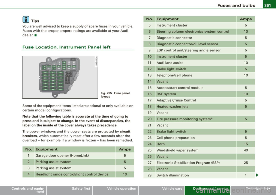
F ig. 295 Fuse pan el
l ayout
Some of the equipment items listed are optiona l or only available on
certain model configurations.
No te t hat th e fo llow ing t able is acc urate a t the time o f goin g to
p re ss an d is s ubject to c hang e. In the e vent of di screpancies, the
lab el on the insi de of th e cover alwa ys ta kes prece dence .
The power windows and the power seats are protected by cir cui t
bre akers,
which automatically reset after a few seconds after the
over load -for example if a window is frozen -has been remedied .
N o. Equipm ent
1 Garage door opener (HomeLinkl 5
Parking assist system 5
3
Parking assist system 5
4
Headlight range control/light control device 10
No .
5
6
7
8
9
10
11
12
13
14
15
16
17
18
19
20
21
22
23
24
25
26
27
28
29
Equipm ent Amps
Instrument c luster
5
Steering column electronics system control 1 0
Diagnostic connector 5
Diagnostic connector/oil level sensor 5
ESP contro l unit/steering angle sensor 5
Instrument cluster 5
Audi lane assist 10
Brake light switch 5
Telephone/cell phone 10
Vacant
Access/start control module
5
RSE system 10
Adaptive Cruise Control 5
Heate d washer jets 5
Vacant
Tire pressure monitoring system*
5
Vacant
Brake light switch
5
Ce ll phone preparation 5
Horn 1 5
Windshield wiper system 40
Vacant
E lectronic Stabilization Program (ESP)
25
Vacant
Switch illumination
1
Vehicle care Do-it-yourself service irechnical data
Page 400 of 408

-Alphabetical index
---=------------------------------------------------
Oil
See Engine oil .... .... ....... .... 311
Older children and safety belts . . . . . . . . 254
On-Board Diagnostic System (OBD) Data Link Connector (DLC) .. .... .... 28
Electronic speed lim iter ... .... .... . 28
Malfunction Indicator Lamp (Mill . ... 27
Open door or rear lid warning ......... 26
Opening Power sunroof . .... .... ... .... .... 65
Operate your vehicle economically and mini-
mize pollution ... ..... ... .... ... 281
Outside air pollution
How to prevent from entering the vehicle
121
Outside mi rrors . ... .. .... .... ...... .. 84
Outside temperature display ........ .. 25
p
Paint
Touch -up
294
Paint No. . . . . . . . . . . . . . . . . . . . . . . . . . . 376
Parking . . . . . . . . . . . . . . . . . . . . . . . . . . . . 135
Automatic transmission . ...... .... 166
Caution when parking near a parking bar -
rier or curb ...... ... .... .... ... 135
Low bumper cover, spoilers and
suspension ......... ....... .... 135
Parking brake
See Electromechanical parking brake 134
Parking on a dec line (downhill) ....... 135
Parking on an incline (uphill) ..... .... 135 Parts replacement
.... ........ .. .. .. 384
PASSENGER A IR BAG OFF light ........ 232
Passenger's seat . . . . . . . . . . . . . . . . . . . . . 87
Pass enger 's seat memory .. .... ....... 95
Passive safety system . . . . . . . . . . . . . . . 200
Pedals ... ..... .. ...... ............ 206
Physica l principles of a frontal collision 212
Pockets . . . . . . . . . . . . . . . . . . . . . . . . . . . . 11
o
Polish ing ... ...... ... .... .... .... .. 293
Power locking switch ........ .... .... . 53
Power locking system ................ 49
Convenience open feature ....... ... 64
Locking and unlock ing the vehicle from
inside ............. ...... .... ... 53
Opening and closing the windows ... 64
Rear lid/trunk lid .. .... .... .... .... 54
Remote control . . . . . . . . . . . . . . . . . . . 48
Selective unlock feature ... .. .. ... .. 52
Settings . . . . . . . . . . . . . . . . . . . . . . . . . 52
Un locking and locking vehic le ... .... 51
Power roof . . . . . . . . . . . . . . . . . . . . . . . . . . 65
Power seat Contro ls .. ....... .... ........ .... 87
Massage function ....... ...... .... 89
Seat adjustment ........ ....... ... 88
Upper th igh support .... .... ....... 88
Power side door closer . . . . . . . . . . . . . . . 53
Pow er steering ... .......... ........ 275
Power sunroof Emergency c losing ............. 66, 67 Power
window switches .. .. .. .... .... . 61
In the driver's door ................ 62
In the front passenger's door ... .... 63
Reactivating the system .... ..... .. . 64
Power windows
Settings ... .... .... ... .... ....... 64
Pregnant women Special considerations when wearing a
safety belt ... .... .... ...... .... 217
Programming the HomeLink® universal re -
mote control .... .... .... ....... 194
Proper occupant seating positions .. ... 202
Proper safety belt position
Proper seating position 216
Front passenger ................ . 203
Occupants .... .... .... ..... .. ... 202
Rear passengers ... .... ... .... ... 204
a
Quartz clock . . . . . . . . . . . . . . . . . . . . . . . . . 13
quattro®
S ee All Whee l Drive .... .... .... ... 275
Question
R
What happens to unbelted occupants? . .
213
Why safety belts? .. ... .... .... ... 211
Radiator fan ......... ... .... .... .... 319
Rain sensor .. .. .. ........ .... ...... . 80
Rain sensor defective ...... ... .... .... 36
Page 402 of 408
___ A---" lp_h_ a_b_ e_ t_ i_ c _ a_ l_ in_d_ e_x ______________________________________________ _
Safety guidelines
Seat adjustment . . . . . . . . . . . . . . . . . . 86
Safety instructions Engine compartment ..... .... .... 309
for a booster seat . . . . . . . . . . . . . . . . 253
for side curtain airbags .... ....... 243
for using a conver tible child safety sea t .
251
for using an infant seat .. ......... 250
for using child safety seats ........ 248
forusingsafetybe lts ... ... .... ... 214
Monitoring the Advanced Airbag System 233
Safety lock Ignition key, automatic transmission 130
Seat adjustment Adjusting the seatback ............. 89
Driver 's seat . . . . . . . . . . . . . . . . . . . . . . 86
Driver's seat memory . . . . . . . . . . . . . . 94
Fron t passenger's seat . . . . . . . . . . . . . 87
Front seats . . . . . . . . . . . . . . . . . . . . . . . 86
Head restraints ............. .. 91,205
Lumbar support .. ............... . 90
Power seat . . . . . . . . . . . . . . . . . . . . . . . 87
Safety guidelines .. ... .... ..... ... 86
Seat belts Why YOU MUST wear them ..... ... 211
Seat memory . . . . . . . . . . . . . . . . . . . . . . . . 94
Seat position Incorrect seat position . . . . . . . . . . . . 205
Seating capacity . .... .... .... ... .... 211 Seating position
Driver . ... .... ...... ...... ...... 202
Front passenger .. .... .... .... ... 203
How to adjust the front seats .. .... 203
Occupants .... .... .... ... ....... 202
Rear passengers
Seats Number of seats 204
211
Selective unlock feature .... ....... ... 52
Selector lever . . . . . . . . . . . . . . . . . . . . . . 167
Service and disposal Safety b elt pret ensioner . ... .... ... 219
Service interval display . . . . . . . . . . . . . . . 27
Service position Windshield wipers . .... .... ....... 82
Servotronic Power steering ...... ...... .... ..
2 7 5
Shift buttons . . . . . . . . . . . . . . . . . . . . . . . 171
Ship Transporting your vehicle . ........ 371
Side airbags Description .... .... .... .... .... .. 239
How they work . . . . . . . . . . . . . . . . . . . 240
Side assist Activating and deactivating ........ 156
Description .......... ...... .... .. 156
Informationa l and alert stage signals 158
Messages in instrument cluster display .. 163
MMI settings ............ .. .. .... 162
Operation . . . . . . . . . . . . . . . . . . . . . . . 158
Safety tips . . . . . . . . . . . . . . . . . . . . . . 164
Sensor detection area . . . . . . . . . . . . 158 Side curtain airbags .
... .. .... .... .. . 242
Description ..... ... .... .... .... .. 242
How they work . . . . . . . . . . . . . . . . . . . 243
Safety instructions . ... .... .... ... 243
Side marker lights .. ....... .... .... ... 69
Sk i sack . . . . . . . . . . . . . . . . . . . . . . . . . . . 102
Snow chains ....... .... ....... .. ... 344
Sockets ........................ 107, 108
Solar blower fan/solar roof . .... ..... . 123
Sound system display Driver information disp lay . .... .... . 25
Spare wheel . . . . . . . . . . . . . . . . . . . . . . . . 352
Speed control sys tem
See Adaptive Cruise Control ...... .. 139
Speed rating letter code .. .... .... ... 340
Speed warning system ........ .... .. . . 37
Speedometer .. .... .... ... ...... ..... 14
Sport Suspension
See Adaptive Air Suspension . .... .. 188
Starting off with a trailer ... ... .... ... 136
Starting the engine .... .... ... ... 129,130
What should I do if the engine does not
start? ... .... .... .... ...... ... . 130
Steering . .... .... .... .... ... .... ... 128
Adjusting s teering column .. .... ... 128
Easy entry feature . .... .... .... ... 129
Locking the steering ....... ....... 129
Malfunction .. .. .. .... .... .... .. . . 33
Steering wheel heating .... .... ... ... 119
Steps for determining correct load limit 336
Stopping the engine .... ... .... .... .. 131