change wheel AUDI S8 2011 Owners Manual
[x] Cancel search | Manufacturer: AUDI, Model Year: 2011, Model line: S8, Model: AUDI S8 2011Pages: 302, PDF Size: 76.07 MB
Page 85 of 302
Depending on the weight of the r ig (vehicle
and trai ler) and the severity of the incline, you
may roll backwards as you start. You can pre
vent roll ing backwards by holding the parking
brake switch(®) pulled out and accelerating -
just as you would when starting on a hill with
a conventional hand brake.
Emergency braking
In the event that the conventional brake sys
tem fails or locks.
... In an emergency, pull the switch(®) and
continue to pull it to slow your vehicle down
with the parking brake.
... As soon as you release t he sw itch (®) or ac-
ce lerate, the braking p rocess stops.
If you pull the sw itch(®) and hold it above a
speed of about 5 mph (8 km/h), t he emergen
cy braking fu nction is in itiated . The vehicle is
b raked at all four wheels by activating the hy
d ra u lic bra ke system. The b rake performance
i s simi lar to making an emergency stop
c::> &. .
In order not to activate the emergency brak
ing by m ista ke, an audible warning tone (b uz
z er) sou nds when the switch®> is pulled. As
soon as the switch(®) is released, or the acce l
erator pedal is dep ressed, emergency brak ing
stops .
A WARNING
Emergency braking should only be used i n
an emergency, when the normal foot brake
has failed or the brake pedal is obstructed.
Using the parking brake to perform emer
gency braking will slow you r vehicle down
as if you had made a fu ll brake applicat ion.
T he laws of physics can not be s uspended
even w ith ESP and its associated compo
nents (ABS, ASR, EDL). In corners and
when road or weather conditions are bad,
a full brake application can cause the vehi
cle to skid or the rear end to break away -
r isking an accident.
On th e ro ad 83
Speed warning system
Introduction
The speed warning system helps you to stay
under a specified maximum speed .
The speed warning system warns you if you
are exceeding the maximum speed that you
have set. You will hear a warning tone when
you r speed exceeds the stored value by ap
proximately 3 mph (3 km/h) . An indicator
li ght . (USA
models) ;a (Canada mode ls) in
the instr ument cluster d isp lay al so tur ns on at
the same time. The indicator light . /.
turns off when the speed decreases be low the
stored maxim um speed .
Se tting a t hreshold is recommended if you
would like to be rem inded w hen you reach a
certain maximum speed. Situations where you
may want to do so incl ude driv ing in a co untry
with a genera l speed limit or if there is a
specified maximum speed for winter tires.
(D Tips
Even though your vehicle is eq uipped w ith
a speed warn ing system, you sho uld still
watch the speedometer to make sure you
are not dr iv ing faster than the speed limit.
Setting the threshold
You can set, change and delete the threshold
in the MMI.
... Select: !CAR ! function button > Car systems
contro l button > Dri ver ass ist > Speed warn
ing .
You can set any threshold between 20 mph
(30 km/h) and 150 mph (240 km/h) . Sett ings
can each be adjusted in increments of 5 mph
(10 km/h).
Page 89 of 302

Adaptive cruis e control and bra kin g guard
vehicles such as motorcycles and bicy
cles.
- The adaptive cruise control system can
not detect people, animals and cannot
detect objects or traffic that crosses your
lane of travel.
- Never drive at speeds that are too fast for traffic, road and weather conditions.
- Never use adaptive cruise control when
you cannot drive safely at a steady speed, including on wind ing roads or
when road conditions are poor (for exam
ple, in construction sites, on ice , gravel,
in fog, heavy ra in or on wet roads that in
crease the risk of hydroplan ing).
- Never follow a veh icle so closely that you
cannot stop your vehicle safely. The
adaptive cruise cont ro l cannot slow or
brake the veh icle safely when you follow
another veh icle too closely. Always re
member that the automatic braking
function cannot bring the vehicle to a
sudden or emergency stop under these
condit ions.
- Never rest your foot on the acce lerator
pedal, especially when the adaptive
cruise control is being used. Pressure on
the accelerator w ill override the adaptive
cruise control braking function and pre
vent the brakes from being applied whe n
adaptive cruise cont ro l detects a situa
t io n when the brakes must be applied.
- Never use adaptive cruise control whe n
the radar sensors cannot accurately de
t ect vehicles moving in t raff ic. The rad ar
sensor's vision can be reduced by heavy
rain, ice, snow, heavy road spray and re
flect ions from guard rails, t unnel ent ran
ces, etc. These and simi lar conditions can
prevent vehicles from being accurately
detected and in some cases they may not
be detected at all .
- Always turn off adaptive cru ise contro l
when entering turn lanes, exit lanes and
constr uction zones or in similar sit ua
t ions because the vehicle will automati
ca lly accelerate to the sto red speed when
the roa d ahead is clear. -
To prevent unintended operation, a lways
sw itch ACC off when it is not being used .
(D Note
The sensors can be moved by impac ts or
damage to the bumper, wheel housing and underbody . Damage in these areas could
change the way the adaptive cru ise control
system and Aud i brak ing guard work to
gether . Have your authorized Audi deale r
check to make s ure that the adaptive
cruise control system is wor king p roperly if
your vehicle had a m ino r frontal impact or
was damaged in the area of the sensors.
In curves
Applies to vehicles: wi th adaptive cruise control
Fi g. 86 Exa mpl e: dri vin g into a curve
When dr iving into a curve¢ fig. 86 and out of
a curve, the adaptive c ruise control may react
to a vehicle in the next lane and app ly the
brakes . You c an override or preven t the brak
ing by pressing the accelerator pedal b riefly .
Stationary objects
Applies to vehicles: wit h adaptive cruise control
Fig. 87 E xam ple: object c hanging l anes a nd s tationa ry
o ~ect
~
8 7
Page 97 of 302
Audi lane assist Lane assist
De scription
App lies to vehicles: with la ne ass ist
Lane assist helps you keep your vehicle in your
lane.
Lane assist uses a camera to detect lane boun
dary lines . If the system detects that your ve
hicle is about to cross a detected lane boun
dary line, the steering wheel
vibrates to alert
the driver . Lane assist is operable when the
line marking the lane is detected on at least
one side of the veh icle. This is ind icated by a
g reen indicator light. in the instrument
cluster.
If the system is in active standby mode and
the turn signal is activated before driving over
the bounda ry line, the warn ing does not occur
since the system allows for intentional lane
changes.
The system is designed for driv ing on free
ways and expanded highways and thus works
only at speeds of 40 mph (65 km/h) or more.
A WARNING
- Lane assist will not keep your vehicle in
your lane . The system only warns the
driver when the vehicle is leaving the
lane . The driver is always responsible for
keeping the vehicle in the lane .
- The camera is not able to detect all lane
boundary lines and in some cases might
also detect lane structures or objects as
boundary lines . This can lead to incorrect
warnings or wa rnings tha t fail to go off
at all.
- The camera's visibility can be impaired by
vehicles ahead of you, for instance, or by
rain, snow, heavy spray o r light sh in ing
into the camera lens. Th is can cause lane
assist to fa il to detect boundary lines.
Audi lane a ssis t 95
Act ivating and deactivating
App lies to vehicles: wit h lane assist
Fig. 95 Turn sign al lever: Lane assist button
Fig . 96 W inds hield: La n e ass ist camera vi ewing w in
dow
"' Press the Q fig . 95 button to activate or de
ac tivate the system . The/: indicator light
on the instr ument cluster will illuminate or
go out.
Instrum ent clu ster ind icat or light
• Rea dy:
The green indicator light shows
that the system is ready to use.
A warning
alerts the driver when the vehicle drives over
detected lane bounda ry lines.
• Not r ea dy: The yellow indicator light
shows that the system is turned on but unable
to send a warning. This can be due to the fol low ing :
- There is no lane boundary line .
- The boundary lines are not detected (e.g .
due to snow, d irt, wet conditions or l ight
shin ing into the camera lens) .
- The vehicle 's speed is below the speed need
ed to activate it, which is about 40 mph (65
km/h).
- The lane is narrower than about 8
ft. (2 .5
m) .
-The curve is too sharp .
Page 161 of 302
airbag system and prevent that system from
working properly in a collision.
There are some important things you have to
know to make sure that the effectiveness of
the system will not be impaired and that dis
carded components do not cause injury or pol
lute the environment.
A WARNING
Improper care, servicing and repair proce
dures can increase the risk of personal in
jury and death by preventing an airbag
from deploying when needed or deploying an airbag unexpectedly:
- Never cover, obstruct, or change the steering wheel horn pad or airbag cover or the instrument panel or modify them
many way .
- Never attach any objects such as cup
holders or telephone mountings to the
surfaces covering the airbag units.
- For cleaning the horn pad or instrument
panel, use only a soft , dry cloth or one
moistened with plain water. Solvents or
cleaners could damage the airbag cover
or change the stiffness or strength of the
material so that the airbag cannot de
ploy and protect properly.
- Never repair, adjust, or change any parts
of the airbag system.
- All work on the steering wheel, instru
ment panel, front seats or electrical sys
tem (including the installation of audio
equipment, cellular telephones and CB
radios, etc .) must be performed by a
qualified technician who has the training
and special equipment necessary .
- For any work on the airbag system, we
strongly recommend that you see your authorized Audi dealer or qualified work
shop.
- Never modify the front bumper or parts
of the vehicle body .
- Always make sure that the side airbag
can inflate without interference:
- Never install seat covers or replace
ment upholstery over the front seat-
Airbag system 159
backs that have not been specifically
approved by Audi.
- Never use additional seat cushions that
cover the areas where the side airbags
inflate.
- Damage to the original seat covers or
to the seam in the area of the side air
bag module must always be repaired
immediately by an authorized Audi
dealer.
- The airbag system can be activated only
once . After an airbag has inflated, it
must be replaced by an authorized Audi
dealer or qualified technician who has
the technical information, training and
special equipment necessary.
- The airbag system can be deployed only
once . After an airbag has been deployed,
it must be replaced with new replace
ment parts designed and approved espe
cially for your Audi model version . Re
placement of complete airbag systems
or airbag components must be per
formed by qualified workshops only.
Make sure that any airbag service action
is entered in your Audi Warranty
& Main
tenance booklet under
AIRBAG REPLACE
MENT RECORD.
- For safety reasons in severe accidents,
the alternator and starter are separated
from the vehicle battery with a pyrotech nic circuit interrupter.
- Work on the pyrotechnic circuit inter rupter must only be performed by a
qualified dealer - risk of an accident!
- If the vehicle or the circuit interrupter
is scrapped, all applicable safety pre
cautions must be followed.
@ For the sake of the environment
Undeployed airbag modules and preten
sioners might be classified as Perchlorate Material - special handling may apply, see
www .dtsc .ca.gov/hazardouswaste/per-
ch lo rate . When the vehicle or parts of the
restraint system including airbag modules
and safety belts with pretensioners are
scrapped, all applicable laws and ..,.
•
•
Page 192 of 302
190 Intelligent technology
Intelligent technology Notice about data
recorded by vehicle
control modules
Your veh icle is not equipped with an Event Da
ta Recorder (EDR), installed by some manu
facture rs for the express purpose of capturing
data for retrieval after an accident or crash
event . EDR's are sometimes ca lled "crash re
corders".
Some state laws restrict the retr ieval or down
loading of data stored by EDR's that were in
stalled in a vehicle for the express purpose of
retrieving data after an accident or crash
event without the owner's consent.
A lthough your vehicle is not equipped with an
EDR, it is equipped with a number of electron
ic control modules for various vehicle systems
such as, for example, eng ine function, em is
sion control, as well as for the airbags and
safety belts.
These electronic contro l modules also record
vehicle-re lated data during normal vehicle op
eration for diagnostic and repair purposes.
The recording capacity of the electronic con
trol modules is limited to data (no sound is re
corded) and only a small amount of data is ac
tually recorded over a ve ry limited pe riod of
time and stored when a system fault or other
cond ition is sensed by a control unit. Some of
the data then stored may re late to vehicle
speed, direction, braking as we ll as restraint
system use and performance in the event of a
crash or other condition. Stored data can only
be read and downloaded with special equip
ment.
Electronic stabilization
program (ESP)
Description
ESP helps to improve road holding and vehicle
dynamics to help reduce the probability of
skidd ing and loss of veh icle control. It works
only when the engine is running. ESP detects certain difficult driving situat
ions, including
when the vehicle is beginning to spin (yaw) out of control and helps you to get the veh icle
back under control by se lectively braking the
wheels, and/or reducing engine power and
providing steer ing assistance to help hold the
vehicle on the driver's intended course. The in
dicator light
liJ in the instrument cluster
blinks when ESP is taking action to help you
control the vehicle.
ESP has limitations.
It is important to remem
ber that ESP cannot overcome the laws of
physics. It will not always be able to help out
under all conditions you may come up against.
For example, ESP may not always be able to
help you master situations where there is a
sudden change in the coefficient of friction of
the road surface. When there is a section of dry road that is suddenly covered w ith water,
slush or snow, ESP cannot perform the same
way it wou ld on the dry surface . If the vehicle
hydroplanes (rides on a cushion of water in
stead of the road surface), ESP will not be
able to help you steer the vehicle because con
tact with the pavement has been interrupted
and the vehicle cannot be braked or steered.
During fast cornering, particularly on winding
roads, ESP cannot always deal as effectively
with difficult driving situations than at lower
speeds. When towing a trailer, ESP is not able
to help you regain control as it would if you
were not tow ing a trailer.
Always adjust your speed and driving style to road, traffic; and weather condit ions. ESP can
not override the vehicle's physical limits, in
crease the available traction, or keep a ve hicle
on the road if road departure is a result of
driver inattention. Instead, ESP improves the
poss ibility of keeping the vehicle unde r con
trol and on the road during extreme maneu
vers by using the driver's steering inputs to
help keep the vehicle going in the intended di
rection . If you are traveling at a speed that
causes you to run off the road before ESP can
provide any assistance, you may not experi
ence the benefits of ESP .
Page 193 of 302
ESP includes and/or works together with the
anti-lock brake assist system (ABS), brake as
sist system, anti -slip regulation (ASR), elec
tronic differential lock (EDL), dynamic steer
ing* and electronic interaxle differential lock*.
ESP is switched on all the t ime . In certa in sit
uations when you need less traction, you can
sw itch
off ASR by pressing the button above
the selector lever. Be sure to switch ASR on
again when you no longer need less traction.
Anti-lock braking system (ABS)
ABS prevents the wheels from locking up
when braking. The vehicle can still be steered even during hard braking . Apply steady pres
sure to the brake pedal. Do not pump the ped
al. A puls ing in the brake pedal indicates that
the system is he lping you to brake the vehicle.
Brake assist system
The brake assist system can decrease brak ing
distance.
It increases braking power when the
driver presses the brake pedal quickly in emer
gency situations. You must press and hold the
brake pedal until the situation is over. In vehi
cles with adaptive cruise control*, the brake
assist system is more sensitive if the distance
detected to the vehicle ahead is too small.
Anti-slip regulation (ASR)
ASR reduces engine power when the drive
wheels begin to spin and adapts the force to
the road conditions. This makes it easier to
start, accelerate and drive up hills .
Electronic differential lock (EDL)
The EDL brakes wheels that are spinning and
transfers the drive power to the other drive
wheel or whee ls if the vehicle is equipped with
a ll whee l drive *. This function is available up
to about 75 mph (120 km/h).
I n extreme cases, EDL automatically switches
off to help keep the brake on the braked wheel
from overheating . EDL will switch on again au
tomatically when conditions have returned to
normal.
Intelligent technology 191
Dynamic steering*
On vehicles with dynamic steering, ESP helps
stabilize the steering in certain situations.
Electronic interaxle differential lock
function*
T he electronic interaxle differential lock func
tion activates when driving th ro ug h curves.
Braking is targeted toward the wheels on the
inside of the curve as needed. This he lps to
minimize front whee l skid, improves traction
and allows for more precise driving through
curves .
A WARNING
- ESP, ABS, ASR, EDL, dynamic steering*
a nd the electronic interaxle differential
loc k fu nction* cannot overcome the laws
of physics. This is especially impo rtant
on slippery or wet roads.
If the systems
begin acting to stabilize your vehicle, you
should immediately change yo ur speed
to match the road and traffic conditions .
Do not let the increased safety provided
by these systems tempt you to take risks.
Doing so will increase the risk of a loss of
veh icle contro l, collision and ser ious per
sonal injur ies.
- Always adapt your speed to road, traffic
and weather conditions. The risk of los
ing con trol of the vehicle increases when
driving too fast, espe cially through
curves and on slippery or wet roads, and
when dr iving too close to vehicles up
ahead. ESP, ABS, the brake assist system,
EDL, ASR, dynam ic steer ing* and the
electronic interaxle differentia l lock func
tion* cannot prevent collisions.
- Always accelerate with special care on
even, smooth surfaces such as those that
are wet or covered with ice and snow.
The drive wheels can spin even with
these assistance systems that cannot al
ways he lp to reduce the risk of loss of ve
hicle contro l.
-
•
•
Page 242 of 302
240 Tires and wheels
Maximum loaded vehicle weight
means t he sum of:
(a) Curb weight
(b) Accessory weight
(c) Vehicle capacity we ight, and
(d) P rod uction options weight
Maximum (permissible) inflation pressure
me ans t he max imum co ld inflation pressu re
to which a tire may be in flate d. Also called
"maxim um inflation p ress ure."
Normal occupant weight
means 150 lbs. (68 kilog rams) times the
nu mbe r of o ccupants seated in t he vehicle up
to the tota l sea ting capaci ty of yo ur vehicle .
Occupant distribution means dist ribution of occupants in a veh icle .
Outer diameter means t he overa ll diameter of a n in flated new
tire.
Overall width
means t he linear dis tan ce between the ex ter i
ors o f th e sidewalls of an inflated tire, in cl ud
ing e levations due to labeling, decorations, or
p rotective bands o r ribs.
Ply
means a laye r of r ubber-co ate d parall el c ords.
Production options weight
means t he comb ined we ight of those installed
regular produc tion options weigh ing ove r 5
l bs . (2 .3 kg) in excess of t hose standard items
which they repla ce, no t previously considered
in cur b weight o r acc essory weig ht, incl uding
h eavy duty brakes, r ide leve le rs, roof ra ck,
h eavy duty ba tte ry, a nd specia l trim .
Radial ply tire
means a pneumatic t ire in which the p ly co rds
t ha t ex tend to the beads are laid a t sub stan
ti ally 9 0 degrees to the ce nt erline o f the
trea d. Recommended inflation pressure
see
<=>
page 239, C old tire infl atio n pressure.
Reinforced tire
means a tire design to operate a t higher loads
and at h igher inflation pressures than t he cor
r espondi ng stan da rd tire. Reinforced tires
may be identifie d as "X L", "xl" , "EX TRA LOAD",
o r "RF " on t he sidewa ll.
Rim
means a metal su ppo rt for a tire or a t ire and
tube assembly upon which the tire beads are
seated.
Rim diameter
means nom inal d iameter of the bead seat. If
you change your wheel s ize, you w ill have to
purchase new tires to match th e new r im di
ameter .
Rim size designation
means r im diameter and width.
Rim width
means nom inal dista nce between rim flan ges .
Sidewall
means tha t port ion of a t ire betw ee n t he
t read a nd bead.
Speed rating (letter code)
means the speed at which a tire is designed to
be driven for extended periods of time. The
r a ti ngs range from 93 mph ( 150 km/h) to
186 mph (298 km/h)
~ page 250. Yo u may
not fi nd this information o n all ti res because
it is no t re quir ed by law.
T he speed rating letter code, wh ere applica
ble , is molde d on the tire sidewall a nd indi
c ates the max imum pe rmissibl e road speeds
<=> A in Winter tire s on page 2 54.
Tire pressure monitoring system*
mea ns a system that detects when o ne or
more of a veh icle 's tires are unde rinf lated an d
ill uminat es a low tir e pr es sure wa rning t ell
t a le.
Page 245 of 302
Tires and wheels 243
change. In the event of discrepancies, the tire
pressure label (On USA vehicles, the tire pres
sure label is located on the dr iver's side B -pil
lar always takes precedence.
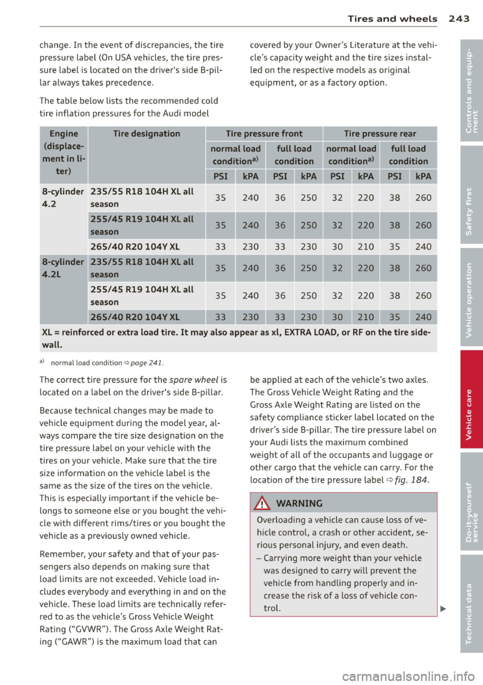
The table be low lists the recommended cold
tire inflation pressures for the A udi model covered
by your Owner 's Literat ure at the vehi
cle's capacity weight and the ti re sizes instal
l ed on the respective models as orig inal
equipment, or as a factory option.
Engine Tire designation Tire pressure front Tire pressure rear
(displace- normal load full load normal load full load
ment in
li-conditiona l
condition conditional
condition
ter) kPA PSI kPA PSI kPA PSI kPA
a-cylinder 235/55 Rla 104H XL all
35 240 36 250 32 220 38 260 4.2
season
255/45 R19 104H XL all
240 36 250 32 220 38 260
season
265/40 R20 104V XL
33 230 33 230 30 210 35 240
a-cylinder 235/55 R18 104H XL all 240
36 250 32 220
38 260
4.2L season
255/45 R19 104H XL all
35 240 36 250 32 220 38 260 season
265/40 R20 104V XL 240
XL= reinforced or extra load tire. It may also appear as xl, EXTRA LOAD, or RF on the tire side-
wall.
al normal load co ndit io n c:, page 24 1.
The correct tire pressure for the spore wheel is
located on a label on the driver's side B-p illar.
Because technical cha nges may be made to
vehicle equipment during the model year , a l
ways compa re the tire size designation on the
tire pressure label on your ve hicle with the
tires on your vehicle . Make sure that the tire
size information on the vehicle label is the
same as the size of the tires on the vehicle.
T his is especially important if the vehicle be
longs to someone else or you bought the vehi
cle wi th different rims/ tires or you bought the
vehicle as a previously owned vehicle .
Remember, your safety and that of your pas
sengers also depends on mak ing sure that
load limits are not exceeded. Vehicle load in
cludes everybody and everything in and on the
veh icle. These load lim its are technically refer
red to as the vehicle's Gross Vehicle Weight
Rating ("GVWR"). The Gross Axle Weight Rat
in g ("GAWR") is the maximum load that can be applied at each
of the vehicle's two axles.
T he Gross Vehicle Weight Rating and the
Gross Axle Weight Rating are listed on the
safety compliance sticker label located on the
driver's side B-pillar . The tire pressure labe l on
your Audi lists the maximum combined
weight of all of the occupants and luggage or
other cargo tha t the veh icle can carry . For the
location of the tire pressure label
c::> fig. 184.
A WARNING
Overloading a vehicle can cause loss of ve
hicle control, a crash or other accident, se
rious personal injury, and even death.
- Carrying more weight than your vehicle
was designed to carry will prevent the
vehicle from handling properly and in crease the risk of a loss of vehicle con
trol.
•
•
Page 247 of 302
Remember that the vehicle manufacturer, not
the tire manufacturer, determines the correct
tire pressure for the t ires on your vehicle.
It is impor tan t to check the tire pressu re when
the t ires a re cold .
- Read the requ ired ti re p ressure from the tire
pressure label. On USA veh icles, the t ire
pressure label is located on the drive r's side
B-pi llar . On Canada vehicles, the tire pres
sure label is located on the driver's side B
pillar.
- Turn the valve stem cap counter-clockwise
to remove it from the tire valve.
- Place the air pressure ga uge on the valve.
- T he tire pressures sho uld only be chec ked
and adjusted when the t ires are cold. The
s li ght ly raised pressures of warm tires must
not be reduced .
- Adjust the tire pressure to the load you are
ca rrying .
- Re insta ll the va lve stem cap on the valve.
When should I ch eck the tire pressur e?
The cor rect tire pressure is espec ially impor
tant at high speeds. The pressure should
therefo re be checked at least once a month
a nd a lways before start ing a journey. Do no t
forget to check the tire pressure for the spare
wheel
r:!> page 261 .
When should I adjust the tire pressures ?
Adjust the tire p ressure to the load you are
carry ing. Afte r changing a wheel
or replacing
wheels you have to adjust the tire pressures
on all wheels . In addition, you must then
store the new tire pressures i n the tire pres
sure monitoring system *
r:!> page 256.
A WARNING
Incorrect tire pressures and/or underinfla
tion can lead sudden tire failure, loss of contro l, col lision, ser ious persona l injury
or even death.
- When the warning symbo l
[I] appears in
the instrument cluster, stop and inspect
the tires .
Tires an d wheel s 245
-Inco rrect tire pressure and/or underinfla
tion can cause increased tire wear and
can affect the handli ng of the vehicle and
stopping ability .
- Incorrect tire pressures and/or underin
flation can a lso lead to sudden t ire fail
ure, including a blowout and sudden de
flation, caus ing loss of veh icle cont rol.
- The drive r is responsib le for the correct
tire pressures for all tires on the ve hicle.
The appli cable pressure values a re locat
ed on a sticke r o n the dr iver's s ide B -pil
lar.
- Onl y when all tir es on the vehicle are fil
led to the co rrect p ressu re, the t ire pres
sure mon itor ing* syste m can work cor
rectly.
- Th e use of incorrect tire p ress ure v alues
can lead to a cciden ts or o ther d amage.
T herefore it is essential that the drive r
observe the specified tire press ure va lues
for the tires and the correct pressures for
the function of the t i re p ress ure monito r
ing system*.
- Always inflate t ires to the recommended
and correct t ire pressure before dr iv ing
off.
- Driving with underinf lated tires bend
more, lett ing them get too hot resulting
in tread separation, sudden tire failure
a nd loss of cont rol.
- Excessive speed and/overloading can
cause heat build- up, sudden tire failure
a nd loss of cont rol.
- If the tire pressure is too low or too high,
the t ires will wear prematurely and the
veh icle w ill not handle well.
- If the tire is not flat and you do not have to change a wheel immediately, d rive at
red uced speed to t he nearest servic e sta
tion to che ck the t ire p ress ure and add
air as req uired.
0 Note
Driving w ithout valve stem caps can cause
damage to the tire valves. To prevent this,
a lways make sure that factory insta lled
•
•
Page 259 of 302

remain continuously illuminated. This se
quence will continue upon subsequent vehicle
start-ups as long as the malfunction exists.
When the malfunction indicator is illuminat
ed, the system may not be able to detect or
signal low tire pressure as intended . TPMS
malfunct ions may occur for a variety of rea
sons, including the installation of replace ment or alternate tires or wheels on the vehi
cle that prevent the TPMS from functioning
properly . Always check the TPMS malfunct ion
tellta le after replacing one or more t ires or
wheels on your vehicle to ensure that the re
placement or alternate tires and wheels allow
the TPMS to continue to function properly.
Tire pressure indicator appears
Applies to vehicles: with tire pressure monitoring system
The tire pressure indicator in the instrument
cluster informs you if the tire pressure is too
low or if there is a system malfunction.
Fig. 189 Display : underinflatio n warning
Fig. 190 Display: System malfu nctio n
Using the ABS sensors, the tire pressure moni
toring system compares the tire tread circum
ference and vibration characteristics of the in
dividual tires . If the pressure decreases in one
or more tires, this is indicated in the instru-
Tires and wheels 257
ment cluster with a warning symbol [I) and a
message
r::!) fig. 189.
The tire pressure monitoring system must be
reset via MMI each t ime the pressures are ad
justed (e.g. when switching between partial
and full load pressure) or after changing or re
placing a tire on your vehicle
r::!) page 258. You
can find the recommended tire pressures for
your vehicle on the label on driver's side 8-pil
lar
r::!) page 242 .
Tire tread circumference and vibration charac
teristics can change and cause a tire pressure
warning if:
- the tire pressure in one or more tires is too
low,
- the tire has structural damage,
- the tir e pressure was changed, wheels rotat-
ed or replaced but the TPMS was not reset
r::!) page 258 .
Warning symbols
[I) Loss of pressure in at least one tire co& .
Check the tire or tires and replace or repa ir if
necessary. The indicator light
[I) in the instru
ment cluster also illuminates
r::!) page 11.
Check/correct the pressures of all four tires
and resetTPMS via MMI.
lli§ffl (Tire Pressure Monitoring System) Tire
pressure! System malfunction.
If llilffl appears after switching the ignition
on or while driving co
fig. 190 and the indica
tor light
[I) in the instrument cluster blinks
for approximately one minute and then stays
on, there is a system malfunction . See your
authorized Audi dea ler as soon as possible .
A WARNING
-If the tire pressure indicator appears in
the instrument cluster display , one or
more of your tires is significant ly under
inflated . Reduce your speed immediately
and avoid any hard steering or braking
maneuvers. Stop as soon as possible and
check the tires and their pressures . In
flate the tire pressure to the proper pres-
sure as indicated on the vehicle's tire .,.