instrument cluster AUDI S8 2012 Owners Manual
[x] Cancel search | Manufacturer: AUDI, Model Year: 2012, Model line: S8, Model: AUDI S8 2012Pages: 300, PDF Size: 75.06 MB
Page 11 of 300
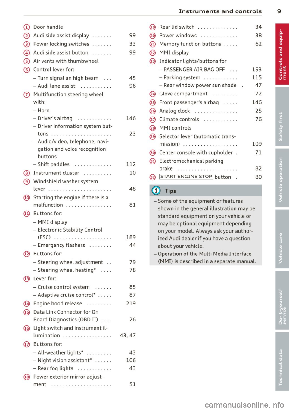
(!) Door handle
@
®
©
®
®
Audi side assist d isplay
Power locking sw itches
Audi side assist button
A ir vents with thumbwheel
Control leve r for :
- Turn signal an high beam
- Audi lane assist ..... ... .. .
0 Multifunction steering wheel
with:
- Horn
- Drive r's airbag
- Driver information system but-
tons . ............... .. .. .
- Audio/video, telephone, navi
gation and vo ice recognition
buttons
- Sh ift padd les ........ .. .. .
@ Instrument cluster .. ... .. .. .
® W indshield washer system
l ever .................... . .
@ Starting the engine i f there is a
malfunction . .. ..... ... .. .. .
@ Buttons for:
- MM I display
- Electronic Stab ility Contro l
( E SC) .. ............. .... .
- Emergency flashe rs . ..... . .
@ Buttons for:
- Steering wheel adjustment
- Steering wheel heating*
@ Lever for:
- Cruise contro l system
99
33
99
45
96
146
23
1 12
10
48
8 1
189
44
79
78
85
- Adaptive cruise cont ro l* . . . . . 87
(§ Eng ine hood re lease . . . . . . . . . 219
@ Data Link Connector for On
Board Diag nostics (OBD II) . . . . 26
@ Light switch and inst rument il-
l umination . . . . . . . . . . . . . . . . . 43, 47
@ Buttons for :
- All-wea ther lights* 43
- Nigh t vision assista nt* . . . . . .
106
- Rea r fog lights . . . . . . . . . . . . 43
@ Power exterior mirror adjust -
ment . . . . . . . . . . . . . . . . . . . . .
51
In strument s and control s 9
@) Rear lid switch .... .. .. ..... .
@ Power w indows .. .......... .
@ Memo ry function buttons .... .
@ MMI display
@ I n d icator lights/buttons for
- P ASSENG ER AIR BAG OFF
- Par king system . .. ........ .
- Rear w indow power sun shade
@ G love compartment . ..... .. .
@
@
@
Front passenger's airbag .... .
Analog clock .. .. .. ........ .
Climate controls
@ MMI controls
@ Se lector lever (a utomat ic trans-
m1ss1on) . ........ .. .. ..... .
@ Center console w ith cupholder
@ El ectromechanical pa rking
br ake .. .. .. .. .... ........ .
@ I START ENGINE STOPI button
(D Tips
34
38
62
153
115
47
72
146
25
76
109
71
82
80
- Some of the equipment o r feat ures
shown in the genera l ill ustration may be
standard equ ipment on your vehicle or
may be opt ional equ ipment depending
on your model. Always ask your author
ized Aud i dea ler if you have a quest io n
about your vehicle .
- Operat ion of the Multi Med ia Interface
(MMI) is described in a separate manua l.
Page 12 of 300
10 Instruments and warning/indicator lights
Instruments and warning/indicator Lights
Instruments
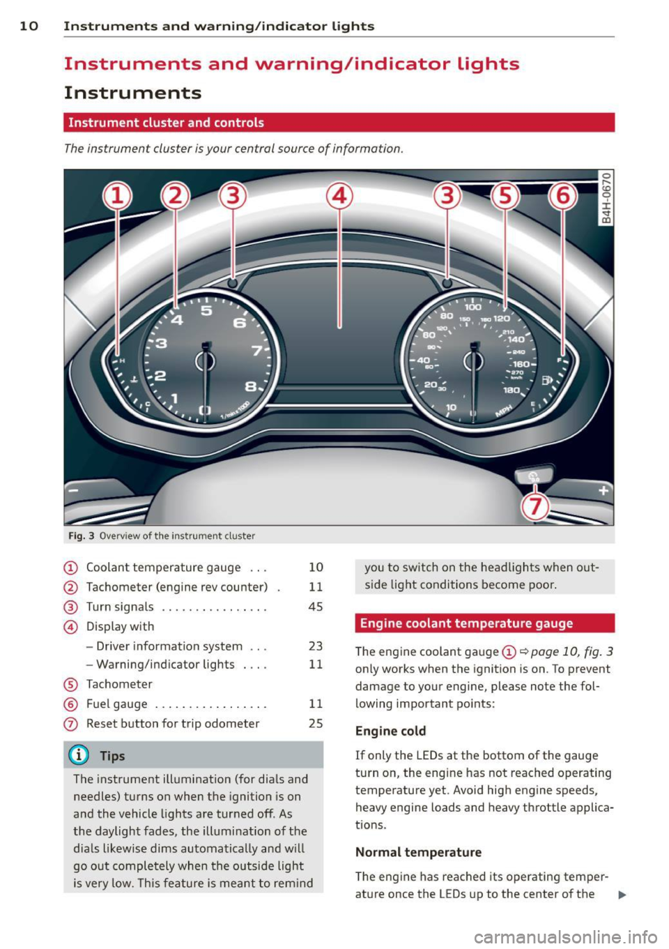
Instrument cluster and controls
The instrument cluster is your central source of information.
Fig. 3 Overview of th e instr ume nt cluster
(!) Coolan t tempera ture gauge ...
@ Tachometer (engine rev counter)
® Turn signals ............. .. .
© D isp lay with
- Driver information system ...
- Warning/ind icator lights
® Tachom eter
® F uel gauge .... ..... ... ... . .
0 Reset b utton for trip odometer
(D Tips
1 0
11
45
23
11
1 1
25
The instrument illumination (for dia ls and
needles) t urns on when the ignition is on
a nd the vehicle lights are tur ned off. As
the daylight fades, the illumination of t he
dia ls likewise dims automatica lly and w ill
go o ut comple tely when the o utsi de light
i s very low. Th is feature is meant t o rem ind you
to sw itch on the head ligh ts when o ut
s id e light condi tions become poor .
Engine coolant temperature gauge
The engine coolant gauge (!) ¢ poge 10, fig. 3
only works when the ignition is on. To prevent
damage to your engine, please note the fol
lowing important po ints:
Engine cold
If only the LEDs at the bottom of the gauge
turn o n, the engine has not reached operating
temperature yet. Avoid hig h engine speeds,
heavy engine loads and heavy throttle applica
tions .
Normal temp erature
The eng ine has reached its operating temper-
at ure once the LEDs up to the center of the .,.
Page 13 of 300
Instrument s and warnin g/indic ator ligh ts 11
gauge turn on under normal d riving condi
tions . The LEDs higher up may turn on when
the eng ine is under heavy load or the exter ior
temperature is high . This is no need to worry
as long as the. warning light in the instru
ment cluster does not illuminate . If the LEDs
in the upper area of the display and the ind ica
tor light . in the instrument cluster display
turn on, the coolant temperature is too high
¢ page 15.
A WARNING
-Always observe the warning in
~ page 213, Engine compartment, be
fore opening the hood and checking the engine coolant level.
- Never open the engine hood if you see or
hear steam, or if you see engine coolant
dr ipping from the engine compartment.
You could burn yourself. Let the engine
cool off first so that you cannot hear or
see any steam or engine coolant .
(D Note
- Mounting additional lights or accessories
in front of the a ir inlets reduces the cool
i ng effect of the rad iator . At h igh outside
temperatures or high eng ine load, the
engine co uld overheat.
- The front spo ile r has been designed to
properly distrib ute the cooling air when
the veh icle is moving. If the spoiler is
damaged, this cou ld red uce the cooling
effect and t he engine co uld then over
heat . Ask your autho rized Audi dea le r for
ass istance.
Tachometer (engine rev counter)
The tachometer indicates the engine RPM
(revolutions per minutes).
If engine R PM drops be low 1,500, you should
downshift to the next lower gear. The red a rea
at the end of the sca le ind icates maxim um
perm iss ible engine RPM after the break-in pe
riod. Before reaching this area, move these
lector lever to position "D (Drive)" or ease
your foot off the accelerator pedal.
@ Note
The tachometer need le should only briefly
be in the red zone: yo u could damage your
engine! The beg inning of the red zone var
i es depending on the engine.
@ For the sake of the environment
Upsh ifting early saves fuel and reduces en
gine noise.
Fuel gauge
The fuel gauge only works when the ignition is
o n.
If the fue l level drops below 4 gallons (15
l ite rs), the bottom LED tu rns red and the indi
cator light
(l1 tu rns on ¢ page 21. The bot
tom LED b link s red when the fue l level is very
l ow .
The possible range based on the current fuel
level is shown in tab@~
page 23, fig. 4.
(D Note
Never run the ta nk complet ely dry. An ir
regular supply of f uel can cause engine
misfiring and fuel cou ld enter the exha ust
system. The cata lytic converter could t hen
overheat and be damaged .
Warning/indicator
lights
Description
T he ind icator lights in the ins trument clus ter
blink or turn on. They indica te f unct ions or
malfunctions
¢ ,& .
Messages may appea r with some indicato r
li ghts. A warning signal will sound at the
same t ime. The indica tor lights and messages
in the center of the displays may be rep laced
by other disp lays. To show them again, select
the tab for ind icator lights and messages us
ing the multifunction steering whee l
¢ page 23. If there are several malfunc
tions, you can display them one at a time us- ing the thumbwheel. ..,.
Page 21 of 300
Instrument s and warnin g/indic ator ligh ts 19
system goes through a learning process fo r
the first few yards . The warning/indicator
light ill uminates. The warn ing/indicator light
goes out as soon as the learning process is
complete.
F or more information about the ESC
~page 187.
ABS/(8) Anti-lock braking system (ABS)
This warning/indicator light monitors the ABS
and the electronic differential lock (EDL).
The warning/indicator ligh t m (USA mod
e ls)
.11] (Canada models) will come on for a
few seconds when the ignition is switched on.
The light will go out after an automatic check
sequence is completed.
There is a malfunction in the ABS wh en :
- T he warning/indicator lig ht does not illumi
nate when you switch the ignition on.
- T he warning/ indicator lig ht does not go out
after a few seconds.
- T he warning/indicator light ill uminates
whi le driving.
The ESC indicator light a lso illuminates if
there is a malfunction in the ABS. The mes
sage
S tabilit y prog ram and ABS faul t! S ee
o w ner' s manu al
also appears in the inst ru
ment cluster display and a warning tone
sounds.
Th e br ake sy ste m will still r espond ev en
with out the a ssis tan ce of the ABS sy ste m .
See your a uth orized Audi deal er as s oon a s
po ssible to re sto re full br akin g perform anc e.
For more information regarding the ABS
¢page 187.
Malfunction in the brake sy stem
If the b rake warning light~ page 14 and the
ABS warning illuminate
together there may be
a ma lfunction in the ABS, and there may also
be a ma lfunction in the brake system itself
¢ &,. The ABS wi ll not work a nd you will no
tice a chang e in br aking r espo nse a nd p er
forman ce.
In the event of a malfunction in the br ake
sys tem
the warning/indicator light _
(USA mode ls)/ . (Canada mode ls) in the in
strument cluster flashes¢
page 14.
Malfunction in th e electronic d iff erential
l o ck (EDL)
The EDL works together with the ABS. The
ABS warning light will come on if there is a
malfunction in the EDL system
¢page 187.
See your authorized Audi dealer as soon as
poss ible.
A WARNING
- If the m (USA models)/ rl] (Canada
models) warning light does not go out,
or if it comes on while dr iving, t he ABS
system is not working properly. The vehi
cle can then be stopped only w ith the
standard brakes (without ABS) . You w ill
not have the protect ion ABS prov ides.
Contact your Audi dea ler as soon as pos
sible.
- USA models: If the - warning light,
the
W warning light and the B warn
ing light come on together, the rear
wheels could lock up first under hard
brak ing. Rear wheel lock-up can ca use
loss of vehicle control and an accident.
Have your vehi cle repaired immediately
by your au thori zed A udi dealer or a quali
fied workshop . Dr ive slowly and avoid
sudden, hard brake applications.
- Canada models: If the brake warning
light ., the
B'J warning light and the
ABS warning light
II] come on together,
the rear wheels could lock up first under
hard braking. Rear whee l lock-up can
cause loss of vehicle contro l and an acci
dent. Have your veh icle repa ired immedi
ately by your authorized Audi dealer or a
qualified workshop. Drive s lowly and
avoid sudden, hard brake applications.
(0 ) Worn brake pads
£i Brake pad s!
Page 27 of 300
Instruments and warning/indicator lights 25
For some vehicle functions, you can access the
trip information from the temporary memory
in the line
(I) c:;; page 23, fig. 5.
@ Tips
- All stored values will be lost if the vehi
cle battery is disconnected.
- Fuel consumptions (average and cur
rent), range and speed are displayed in
metric units on Canadian models.
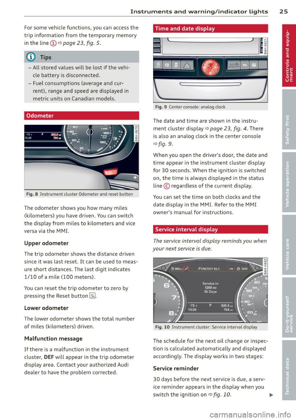
Odometer
Fig. 8 Instrument cluster Odometer and reset b utto n
The odometer shows you how many miles
(kilometers) you have driven. You can switch
th e display from miles to kilometers and vice
versa via the MMI.
Upper odometer
The trip odometer shows the distance driven
since it was last reset.
It can be used to meas
ure short distances. The last digit indicates 1/10 of a mile (100 meters).
You can reset the trip odometer to zero by
pressing the Reset button~-
Lower odometer
The lower odometer shows the total number
of miles (kilometers) driven .
Malfunction message
If there is a malfunction in the instrument
cluster,
DEF will appear in the trip odometer
display area. Contact your authorized Audi
dealer to have the problem corrected .
Time and date display
...
I~
Fig. 9 Cente r console : analog clock
The date and time are shown in the instru
ment cluster display
c:;; page 23, fig. 4. There
is also an analog clock in the center console
¢fig . 9 .
:r
~
When you open the driver's door, the date and
time appear in the instrument cluster display
for 30 seconds. When the ignition is switched
on, the time is always displayed in the status
line © regardless of the current display.
You can set the time on both clocks and the
date display in the MMI. Refer to the MMI
owner's manual for instructions.
Service interval display
The service interval display reminds you when
your next service is due .
Fig. 10 Instrument cluster: Serv ice inte rval disp lay
The schedule for the next oil change or inspec
tion is calculated automatically and displayed
accordingly. The display works in two stages:
Service reminder
30 days before the next service is due, a serv
ice reminder appears in the display when you
switch the ignition on
¢fig. 10. ..,.
Page 28 of 300
26 Instruments and warning /indicator lights
After abo ut 5 seconds the display sw itches
back to normal. The distance and time re
maining are updated eac h time the ignition is
switched on until the date due for service is
reached .
Service due
When the due date for service is reached , the
message
Serv ice due! appears in the instr u
ment cluster immediately after you switch the
ignit io n on . Additionally, a warning tone
sounds . After about
5 seconds the display
sw itches back to no rmal.
Calling up the service schedules
If or when an oil change or inspection is due,
can be shown in the MMI d isplay by select ing
the service interva l display in the car menu .
Select the
!CAR ! function button> Car sys
tems
co ntrol button > Servicing & checks >
Service interval disp lays.
Re setting the service interval display
Your author ized Audi dealer w ill reset the cor
responding service sched ule after performing
the app rop riate se rv ice on you r vehicle . You
a lso have the possibili ty to reset the o il
change sched ule after having performed an
oil c hange a ccor ding to Audi s pecifications.
Selec t the
I CAR I func tion button > Car sys
tems
c on trol b utt on > Servicing & checks >
Service interval displays > Reset oil change
inte rval.
{[) Note
If you disconnec t the b attery termi nals, no
calc ulations can be made for the serv ice
interva l display during this t ime and no
service rem inder w ill appea r. Remembe r
that obse rv in g the prope r se rv ice interva ls
is vitally impo rtant to extend ing the life of
your v eh icle, part icu larly the eng ine, and
main taini ng its va lue . Ev en i f th e m ileage
driv en is low, th e maximum per iod o f one
yea r from o ne se rvi ce to the nex t mus t not
be e xcee ded.
(D Tips
- Do not reset the display betwee n oil
c h anges, otherwise the d isp lay w ill be in
co rrect.
- Th e info rmation in the Se rvice Remin der
remains stored even w hen t he vehicle
battery is disconnected.
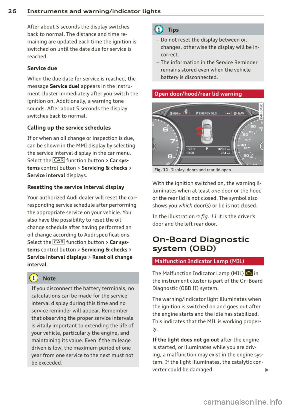
Open door /hood /rear lid warning
F ig. 1 1 Display : doors and rea r lid open
Wi th the ig nition sw itched on, t he warn ing il
lu minates when at least
one doo r or th e hood
or the rear lid is not closed. The sym bo l also
shows you
which d oor(s) or lid is not closed.
In the illustration
r:!> fig. 11 it is the driver's
doo randt he leftrea rdoo ~
On-Board Diagnostic
system (OBD)
Malfunction Ind icator Lamp (MIL )
The Ma lf u nction Indicator Lam p (M IL) f-4 in
t h e instr ume nt cluster is part of t he On -Board
Diagnostic (OBD
II) system .
T he wa rn ing /indic ator lig ht ill uminates when
the ignitio n is switched on and goes ou t after
t h e engine sta rts and t he id le has sta bilized.
This ind icates that the MIL is working proper
ly.
If the light does not go out afte r the e ngine
is starte d, or illumi nates w hile you are driv
i ng, a mal function may exist in the engine sys
tem . If t he light illum inates, t he catalytic con-
verter could be damaged .
IIJ,-
Page 31 of 300

Removing the mechanical key
Fig. 14 Remote control maste r key : re mov ing the me
c han ical key
• Press the release button@ ¢ fig. 14.
• Pull the mechanica l key @ out of the mas
ter key.
Using the mechan ica l key, you can:
- lock and unlock* the storage compartment
on the passenger's side
<=:> page 71.
-lock and unlock the vehicle manually
c:>page 33 .
-lock the front and rear passenger doors me
chanically
c:> page 34.
- unlock the rear lid manua lly ¢ page 37 .
Check light and battery in the master
key
Fig. 15 Remote master key : Re mov ing the battery
holder
Check light in the master key
The check light @<=:> fig. 15 in the master key
prov ides information about different cond i
tions.
• The check light turns on brief ly once when a
button is pressed, and during an "inqu iry"
by the convenience key system .
Opening and closing 29
• If the check light does not come on, the
battery is dead and has to be replaced. In
add ition, when the battery is dead
the m
indicator light appears in the instrument
cluster display as well as the message
Please change the key battery .
Master key battery replacement
We recommend having the battery changed
by an authorized Audi dealer. However, if you
wish to replace the dead battery yourse lf , pro
ceed as follows:
• Remove the mechanical key
c:> page 29.
.. Press the re lease button ® c:> fig. 15 on the
battery holder and at the same time pull the
battery holder out of the master key in the
direction of the arrow .
.. Install the new battery CR 2032 with the
"+" sign facing down.
• Push the battery holder carefu lly into the
master key.
• Install the mechan ical key.
(® For the sake of the environment
Dispose of dead batteries properly so as
not to poll ute the environment.
(D Tips
The replacement battery must be the
same specification as the original.
Electronic immobilizer
The immobilizer helps to prevent unauthor
ized use of your vehicle .
A computer chip inside your key automatically
deact ivates the electronic immobilizer when
the key is inside the vehicle . When you remove
the key from the vehicle, the elect ronic immo
bilizer is automatically activated once again.
& WARNING
Always take the key with you when you
leave the vehicle. The key can disarm the
e lectronic engine immobilizer and permit
an unauthorized person to start the engine
and enable operation of the vehicle
IIJI,-
Page 41 of 300

- The buttons for the power sun shades* in
the side windows,
- The buttons for the power sun shade* in the
rear window,
- Front passenger power seat adj ustment *
button.
_& WARNING
- When you leave your vehicle -even if on
ly briefly- always take the ignition key
with you. This applies particularly when
children remain in the veh icle. Otherw ise
the ch ildren could start the engine or op
erate electrical equ ipment (e.g. power
w indows) . The power windows are func
t ional until t he driver's door or passeng
er's door has been opened.
- Be careful when closing the windows.
Check to see that no one is in the way, or
serious injury could result!
- When lo cking the veh icle from outside,
t he ve hicle must be unocc upied s in ce the
w indows can no longer be opened in an
emergency.
(D Tips
- The dr iver can lower or raise the power
sun shades * in the side windows by us ing
swi tches © and
@.
-After the ignition has been switched off,
the windows can still be opened o r
closed for about 10 minutes . The powe r
windows are not switched off until the
driver's door or passenger's door has
been opened.
What to do after a malfunction
The one-touch open and close function must
be reactivated if the battery hos been discon
nected.
• Pull and hold the power window switch un
ti l the window is fully closed.
• Release the switch and then pull it again for
at least one second .
Openin g an d clos ing 39
Valet parking
The valet parking feature protects the lug
gage comportment from unauthorized ac
cess.
F ig. 30 Valet par king button
Wi th "valet parking" a ctivated, the rear lid
cannot be opened.
• Remove the mechanical key
c::;, page 29 .
• Open the glove compartment and activate
c::;, fig. 30 the "valet parking" feature by
pressing the
! VALET I b utton. The indicator
light in the swi tch illuminates.
• Close the glove compartment and lock it
w ith the mechanical key.
• Leave the master key with the se rvice per
sonnel for park ing and keep the mechanical
key with you.
When the "valet parking" feature is activated:
- the unlocki ng button fo r the rear l id
c:s in
the dr ive r's door is inactive
- the button
c:s on the mas ter key is inac tive
- the opening handle in the rear lid is inact ive .
The vehicle can be driven and locked and un
locked with the master key. Access to the lug
gage compartment is blocked.
When the valet parking function is switched
on, the message
Vale t par king acti vated ap
pears in the instrument cluster display when
you sw itch the ignition on.
Page 46 of 300
44 Clear vision
Highway light function* (vehicles with LED
headlights) -this function adapts the lighting
for highway driving based on vehicle speed.
.&_ WARNING
- Automatic headlights are only intended
to assist the driver. They do not relieve
the driver of his responsibility to check
the headlights and to turn them on man
ually according to the current light and
visibility conditions. For example, fog
cannot be detected by the light sensors.
So always switch on the headlights §.0
under these weather conditions and
when driving in the dark.
- Crashes can happen when you cannot see the road ahead and when you cannot be
seen by other motorists. Always turn on
the headlights so that you can see ahead
and so that others can see your car from
the back.
- Please observe legal regulations when
using the lighting systems described.
(D Note
The rear fog lights should only be turned
on in accordance with traffic regulation, as
the lights are bright for following traffic.
@ Tips
- The light sensor* for automatic dynamic
headlight range control* is located in the
rear view mirror mount. You should
therefore not apply any stickers to the
windshield in this area in order to pre
vent malfunctions or failures .
- In the event of a light sensor malfunc
tion, the driver is notified in the instru
ment cluster display¢
page 21 .
- You will hear a warning tone if you open
the driver door when the exterior lights
are switched on.
- In cool or damp weather, the inside of
the headlights, turn signals and tail
lights can fog over due to the tempera
ture difference between the inside and
outside. They will clear shortly after switching them on. This does not affect
the service life of the lighting.
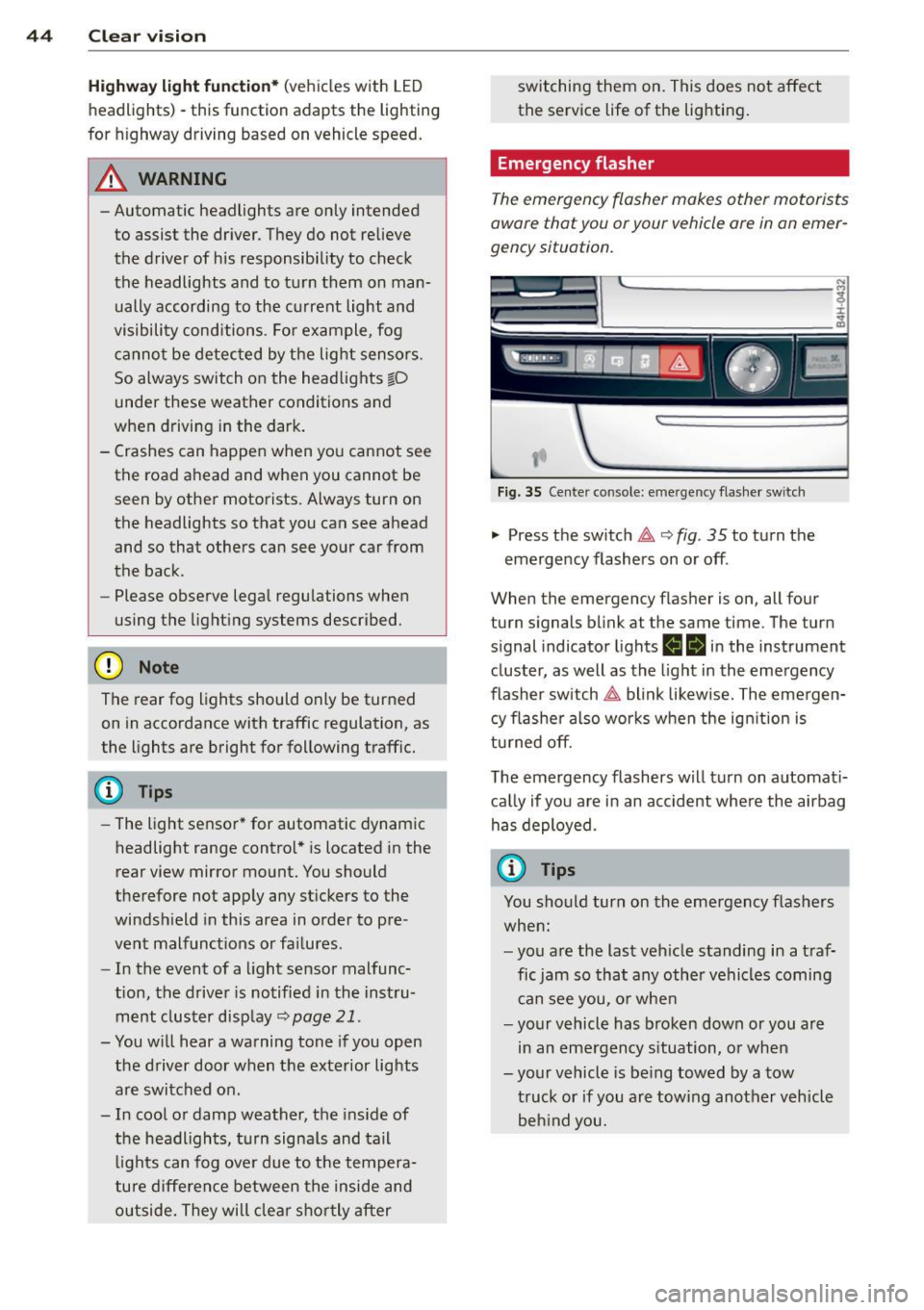
Emergency flasher
The emergency flasher makes other motorists
aware that you or your vehicle ore in an emer
gency situation.
,--~
,_'
. ;.' --- --~-.sc-
Fig. 35 Center console: emergency flasher switch
.,. Press the switch 11 ¢ fig. 35 to turn the
emergency flashers on or off .
When the emergency flasher is on, all four
turn signals blink at the same time. The turn
s ignal ind icator lights
ea in the instrument
cluster, as well as the light in the emergency
flasher switch
11 blink likewise. The emergen
cy flasher also works when the ignition is
turned off.
The emergency flashers will turn on automati
cally if you are in an accident where the airbag
has deployed.
(D Tips
You should turn on the emergency flashers
when:
- you are the last vehicle standing in a traf
fic jam so that any other vehicles coming
can see you, or when
- your vehicle has broken down or you are
in an emergency situation, or when
-your vehicle is being towed by a tow
truck or if you are towing another vehicle
behind you.
Page 48 of 300
46 Clear vis ion
instrument cluste r illuminates when the
high beams are on.
- T he
headlight flash er works only as long as
yo u hold the lever - even if there are no
l ights turned on . The ind icator light
Bl in
the instrument cluster i lluminates when you
use the headlight flasher.
A WARNING
Do not use the high beam or headlight
flasher if you know that these could blind
oncoming traffic.
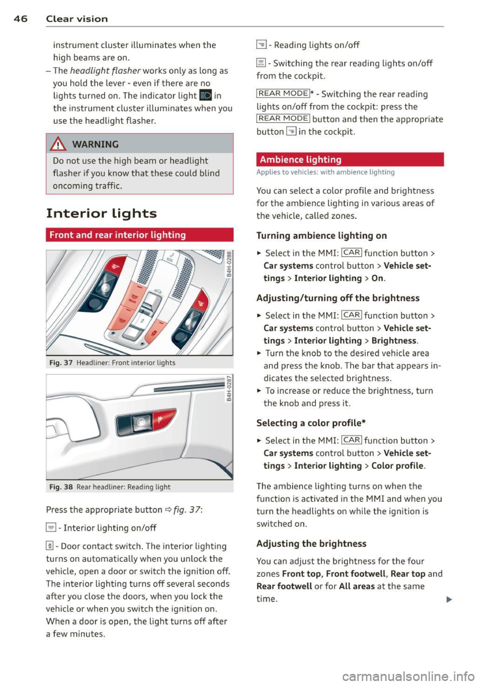
Interior lights
Front and rear interior lighting
Fi g. 37 Headl iner: Front in te ri or lig hts
F ig . 3 8 Re ar headli ne r: Rea din g lig ht
Press the appropriate b utton q fig . 3 7:
El -Interior lighting on/off
1!1-Door contac t switch . The inter ior light ing
turns on automatica lly when you unlock the
vehicle, open a door or switch the ignition off.
The interior lighting turns off several seconds after you close the doors , when you lock the
vehicle or when you switch the ignition on .
When a door is open, the light t urns off afte r
a few minutes .
L:!l-Read ing lights on/off
~ - Switching the rear read ing lights on/off
from the cockpi t.
IREAR MODEt* - Sw itch ing the rea r readi ng
lights on/off from the cockpit : pr ess the
I REAR MODE i button and t hen t he appropriate
button
L:!l i n t he cockpit .
Ambience lighting
Applies to vehicles: with ambience lighting
You can select a color profile and br igh tness
for the ambience light ing in various areas of
t h e ve hicle, called zones .
Turning ambience lighting on .,. Sele ct in the
M MI: ICAR lfun ction bu tton>
Car sy stem s control b utton > Vehicle set
ting s
> Interior lighting > On.
Ad justing/turning off the brightness
.,. Select in the
MMI: ICA Rlfunction button>
Car sy stem s control b utton > Vehicle set
ting s
> Interior lighting > Brightne ss .
.,. Tur n the knob to the desired veh icle area
and p ress the knob. The bar that appears in
dicates the selected brightness .
.,. To increas e or reduce the brightness, turn
the knob and press it .
Select ing a color p rofile*
.,. Select in the
MMI: ICAR lfunction button>
Car sy stem s control b utton > Vehicle set
ting s
> Interior lighting > Color profile .
T he ambience ligh ting tu rns on when the
f unct ion is act ivated in the
MMI and w hen you
turn the headlights on while the ign ition is
switched on .
Adjusting the brightness
You can adjus t the br igh tness fo r the fou r
zones Front top , Front footwell , Re ar top and
Rear footwell or for All areas at the same
t ime . ..,.