AUDI S8 2016 Owners Manual
Manufacturer: AUDI, Model Year: 2016, Model line: S8, Model: AUDI S8 2016Pages: 302, PDF Size: 75.68 MB
Page 261 of 302
Replacing wheels
Before changing a wheel
Observe the following precautions for your own
and your passenger's safety when changing a
wheel.
.,. After you experience a tire failure, pull the car
well away from moving traffic and try to reach
level ground before you stop¢.,&. .
.. All passengers should
leave the car and move
to a safe location (for instance, beh ind the
guardrail) ¢.,&. .
.,. Engage the
parking brake to prevent your vehi
cle from rolling unintentionally ¢.,&. .
.. Move
selector lever to position P ¢ .,&. .
1> lfyou are towing a trailer, unhitch the trailer
from your vehicle.
.,. Take the
jack and the spare tire out of the lug
gage compartment,
¢page 257.
..&, WARNING
You or your passengers could be injured wh ile
changing a wheel if you do not follow these
safety precautions:
- If you have a flat tire, move a safe distance
off the road. Turn off the engine, turn the
emergency flashers on and use other warn
ing devices to alert other motorists.
- Make sure that passengers wa it in a safe
place away from the vehicle and well away
from the road and traffic.
- T o help prevent the vehicle from moving
sudden ly and possibly slipping off the jack,
always fully set the parking brake and block
the wheel diagonally opposite the wheel be
ing changed. When one front wheel is lifted
off the ground, plac ing the Automatic
Transmission in "P" (Park) will
not prevent
the vehicle from moving.
- Before you change a wheel, be sure the
ground is level and firm . If necessary, use a
sturdy board under the jack .
- Always store the vehicle tool k it, the jack
and the replaced tire in the luggage com
partment ¢
page 135.
Emergency assistance
{!) Tips
Before changing the wheel, you must activate
the jacking mode, so that the automat ic con
tro ls for the Adaptive Air Suspension do not
make it more difficult to lift the vehicle with
the jack ¢
page 261 .
Changing a wheel
When you change a wheel , follow the sequence
described below step-by-s tep and in exactly tha t
order .
l. Activate the vehicle jack mode ¢ page 261 .
2. Remove the decorative wheel cover*. For
more details see also¢
page 260, Decora
tive wheel covers
or¢ page 260, Wheels
with wheel bolt caps .
3. Loosen the wheel bolts¢ page 260.
4. Locate the proper mounting point for the
jack and align the jack below that point
¢ page 261 or¢ page 262.
5. Raise the car with the jack¢ page 261 or
¢page 262.
6. Remove the wheel with the flat tire and then
install
the spare ¢ page 263.
7. Tighten all wheel bolts lightly .
8.
Lower the vehicle with the jack .
9. Use the wheel bolt wrench and
firmly tighten
all wheel bolts<=>
page 260.
10. Replace the decorative wheel cover*.
11. Deactivate the vehicle jack mode in the MMI :
I CAR! function button > Car systems contro l
button
> Servicing & checks > Air susp.: jack
mode > Off.
The vehicle jack mode switches off automatically
at speeds above 10 km/h .
..&, WARNING
Always read and follow all WARNINGS and in
formation
¢ .&. in AB: Raising the vehicle on
page 262
and ¢ page 264.
259
Page 262 of 302
Emergency assistance
After changing a wheel
A wheel change is not complete without the do
ing the following .
• Always store the vehicle tool kit, the jack* and
the replaced tire in the luggage compartment
<=>page 135.
• Check the tire pressure on the spare wheel im
mediate ly after mounting it.
• As soon as possible, have the
tightening tor
ques
on all wheel bolts checked with a torque
wrench. The correct tightening torque is 90 ft
lb (120 Nm).
• Have the flat tire
replaced as soon as possible.
@ Tips
- If you notice that the whee l bolts are cor
roded and difficu lt to turn while changing a
tire, they should be replaced before you
check the tightening torque .
- Drive at reduced speed until you have the
tightening torques checked.
- After changing a wheel, the tire pressure in
a ll four tires must be checked/corrected and
the tire pressure mon itor ing indicator must
be stored in the MMI
c> page 255.
Decorative wheel covers
App lies to: vehicles with decorative wheel covers
The decorative wheel covers must be removed
first to access the wheel bolts .
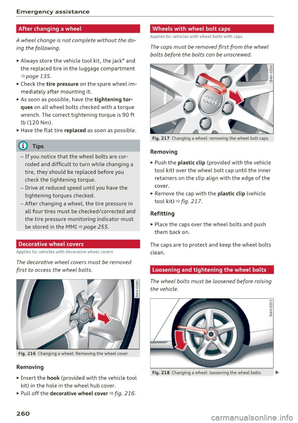
Fig. 216 Chan gin g a w heel : Removing the whee l cover
Removing
• Insert the hook (provided with the ve hicle tool
kit) in the hole in the wheel hub cover.
• Pull off the
decorative wheel cover c> fig. 216.
260
Wheels with wheel bolt caps
Applies to: vehicles with wheel bo lts with caps
The caps must be removed first from the wheel
bolts before the bolts can be unscrewed .
Fig. 217 Changing a wheel: removing the wheel bo lt caps
Removing
• Push the plastic clip (provided with the vehicle
tool kit) over the whee l bolt cap until the inner
retainers on the clip align with the edge of the
cover.
• Remove the cap with the
plastic clip (vehicle
tool kit)
<=> fig. 217 .
Refitting
• Place the caps over the wheel bolts and push
them back on .
The caps are to protect and keep the wheel bolts
clean.
Loosening and tightening the wheel bolts
The wheel bolts must be loosened before raising
the vehicle.
Fig. 218 Chang ing a wheel: loosening the wheel bo lts
Page 263 of 302
Loosening
• Slide the wh eel wr ench onto the wheel bolt as
far as it will go.
• Take tight hold of the
end of the wrench handle
and turn the wheel bolts
counter-cloc kwise
about one single turn in the direction of arrow
<=>fig. 218.
Tightening
• Slide the wheel wrench onto the wheel bolt as
far as it w ill go.
• Take tight hold of the
end of the wrench handle
and turn each wheel bolt
cloc kwise until it is
seated.
A WARNING
- Do not use force or hurry when changing a
wheel· you can cause the vehicle to slip off
the jack and cause se rious personal injur ies.
- Do not loosen the wheel bolts more than
one turn
before you raise the vehicle with
the jack. -You risk an injury.
(D Tips
- Never use the hexagonal socket in the han
dle of the screwdriver to loosen or tighten
the wheel bo lts .
- If a wheel bolt is
very tight, you may find it
easier to loosen by carefully push ing down
on the end of the wheel bo lt wrench with
one
foot only . As you do so, hold on to the
car to keep your balan ce and take care no t
to slip .
Emergen cy a ssis tanc e
A8: Raising the vehicle
The vehicle must be lifted with the jack first be
fore the wheel can be removed.
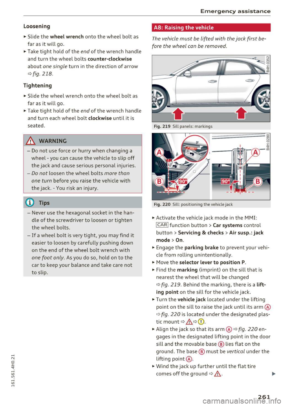
Fig . 219 Sill panels: markings
F ig . 220 S ill: positioning the vehicle jack
• Activate the vehicle jack mode in the MMI:
!CARI function button > Car systems control
button
> Ser vicing & chec ks> A ir su sp .: jac k
mode > On .
• Engage the pa rki ng br ake to prevent your veh i
cle from rolling unintentionally.
"' Move the
selector l eve r to position P .
"' Find the mark ing (imprint) on the sill that is
nea rest the wheel that will be changed
<=> fig. 219 . Behind t he marking, there is a lift
ing point on the sill fo r th e vehi cle jack.
• Turn the
vehicle jack located under the lifting
point on the sill to raise the jack unt il its arm @
<=> fig. 220 is located under the designated plas
tic mount<=> .&.<=>CD.
"' Align the jack so that its arm@<=>
fig. 220 en
gages in the designated lifting point in the door
sill and the movable base @ lies flat on the
gro und . The base @ must be
vertical under the
lifting point@.
"' Wind the jack up fu rther until the f lat ti re
comes off the ground ¢..&._ . ""
261
Page 264 of 302
Emerg ency assis ta nce
Position the vehicle jack only under the designat
ed lifting po ints on the sill
¢fig. 219. There is ex
actly
one locat ion for each wheel. The jack must
not be positioned at any other location
c> &<=>0.
An uns table su rf a ce under the jack can cause the
vehicle to slip off the jack. Always provide a firm
base for the jack on the ground . If necessary
place a sturdy board or similar support under the
jack. On
hard, slippery su rfaces (such as tiles)
use a rubber mat or similar to prevent the jack
from slipping
c> ,&..
A WARNING
-
-Yo u or your passengers could be injured
wh ile chang ing a wheel if you do not follow
these safety precaut ions:
- Position the vehicle jack only at the desig
nated lifting points and align the jack.
Otherw ise, the vehicle jack cou ld slip and
cause an injury if it does not have suffi
cient hold on the vehicle.
- A soft or unstable s urface under the jack
may cause the vehicle to slip off the jack.
Always p rovide a firm base for the jack on
the ground. If necessary, use a sturdy
board under the jack.
- On hard, s lippery surface (such as tiles)
use a rubber mat or similar to prevent the
jack from slippi ng.
- T o help prevent injury to yo urself and yo ur
passenge rs:
- Do not raise the vehicle unti l you are sure
the jack is securely engaged .
- Passengers must not remain in the vehicle
when it is jacked up.
- Make sure that passengers wait in a safe
place away from the vehicle and well away
from the road and traffic.
- Make sure jack position is correct, adjust
as necessary and then continue to raise
the jack.
- Changes in temperature or load can affect
the height of the vehicle.
(D Note
Do not lift the vehicle by the sill . Position the
vehicle jack only at the designated lifting
262
points on the sill. Otherwise, your vehicle wi ll
be damaged .
(1) Tips
The vehicle jac k mode sw itches off automa ti
cally at speeds above 10 km/h.
58: Raising the vehicle
The vehicle must be li~ed with the jack first be
fore the wheel can be removed .
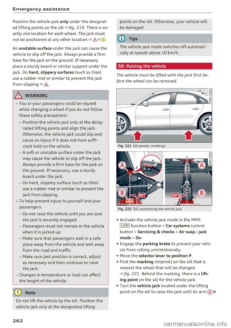
Fig. 221 Sill panels : ma rkings
F ig. 222 Sill : pos ition ing the veh icle jack
.. Activate the vehicle jack mode in the MMI :
!CARI function button > Car s yst ems control
button
> Ser vicin g & che cks > A ir su sp .: jack
mode > On .
.. Engage the parking brake to prevent your vehi
cle from rolling uni ntentiona lly .
.. Move the
select or lever t o positi on P.
.. Find the marking (imprint) on the sill that is
nearest the wheel that will be changed
<=>fig. 221 . Behind the marking, there is a lift
ing point
on the sill for the vehicle jack.
.. Turn the
vehicl e jack located under the lifting
point on the sill to raise the jack until its arm
@ Ill>
Page 265 of 302
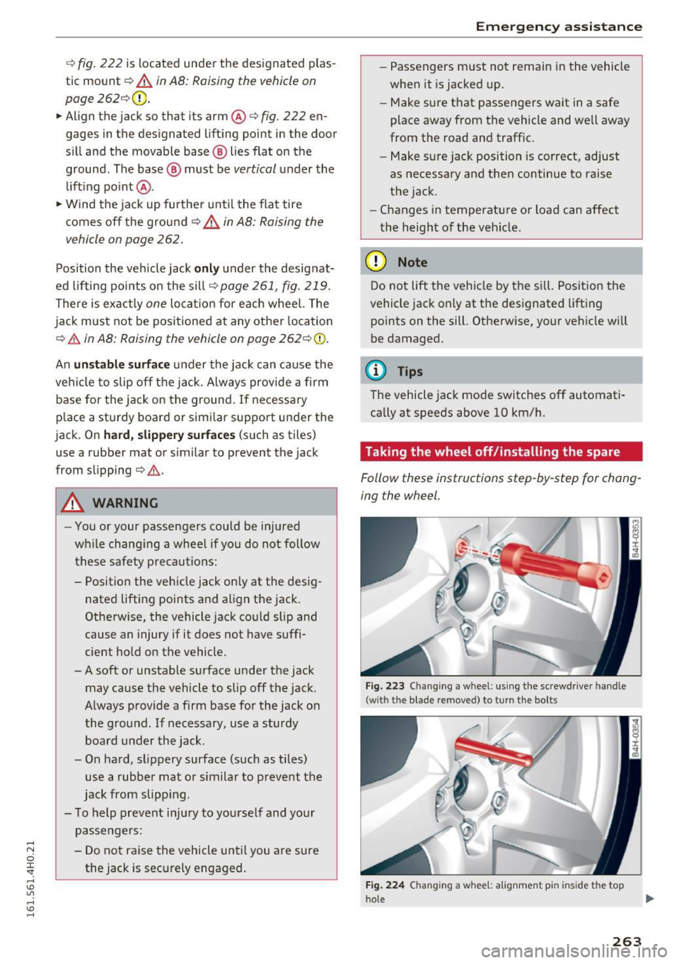
c::> fig. 222 is located under the designated plas
tic mount
c::> A in AB: Raising the vehicle on
page
262 <=:>(D.
.. Align the jack so that its arm®
c::> fig. 222 en
gages in the designated lifting point in the door
sill and the movable base ® lies flat on the
ground . The base ® must be
vertical under the
li ft ing po int @ .
.,. Wind the jack up further unt il the fla t tire
c omes off the ground
c::> A in AB: Raising the
vehicle on page
262.
Position the veh icle jack
onl y under the designat
ed lifting points on the sill
<=:>page 261, fig. 219 .
There is exactly one locatio n for each wheel. The
jack must not be positioned at any other location
c::> .&. in AB: Raising the vehicle on page 262<=:> 0.
An
un stabl e surface under the jac k can ca use the
vehi cle to slip off the jack . Always provide a firm
base for the jack on the ground. If necessary
p lace a sturdy board or similar support under the
jack. On
hard , slippery surfaces (such as tiles)
use a rubber mat or similar to prevent the jack
from slipping
c::> .&. .
A WARNING
-
-You or your passengers could be injured
wh ile chang ing a wheel if you do not follow
these safety precautions :
- Position the vehicle jack only at the desig
nated lifting points and align the jack.
Otherw ise, the vehicle jack cou ld slip and
cause an injury if it does not have suffi
cient hold on the vehicle.
- A soft or unstable surface under the jack
may cause the vehicle to slip off the jack.
Always provide a firm base for the jack on
the ground .
If necessary, use a sturdy
board under the jack.
- O n hard, s lippery surface (such as tiles)
use a rubber mat or s imilar to prevent the
jack from slipp ing.
- To help prevent inju ry to yourself and your
passenge rs:
- Do not raise the vehicle unt il you are sure
the jack is secure ly engaged .
Emergen cy a ssis tanc e
-Passengers must not remain in the vehicle
when it is jacked up.
- Make sure that passengers wait in a safe
place away from the vehicle and well away
from the road and traffic.
- Make sure jack position is correct, adjust
as necessary and then continue to raise
the jack .
- Changes in temperature or load can affect
the height of the veh icle.
(D Note
Do not lift the vehicle by the si ll. Position the
vehicle jack on ly at the designated lift ing
points on the sill. Otherwise, your veh icle w ill
be damaged.
@ Tips
The vehicle jack mode switches off automati
cally at speeds
above 10 km/h.
Taking the wheel off/installing the spare
Follow these instructions step-by-step for chang
ing the wheel .
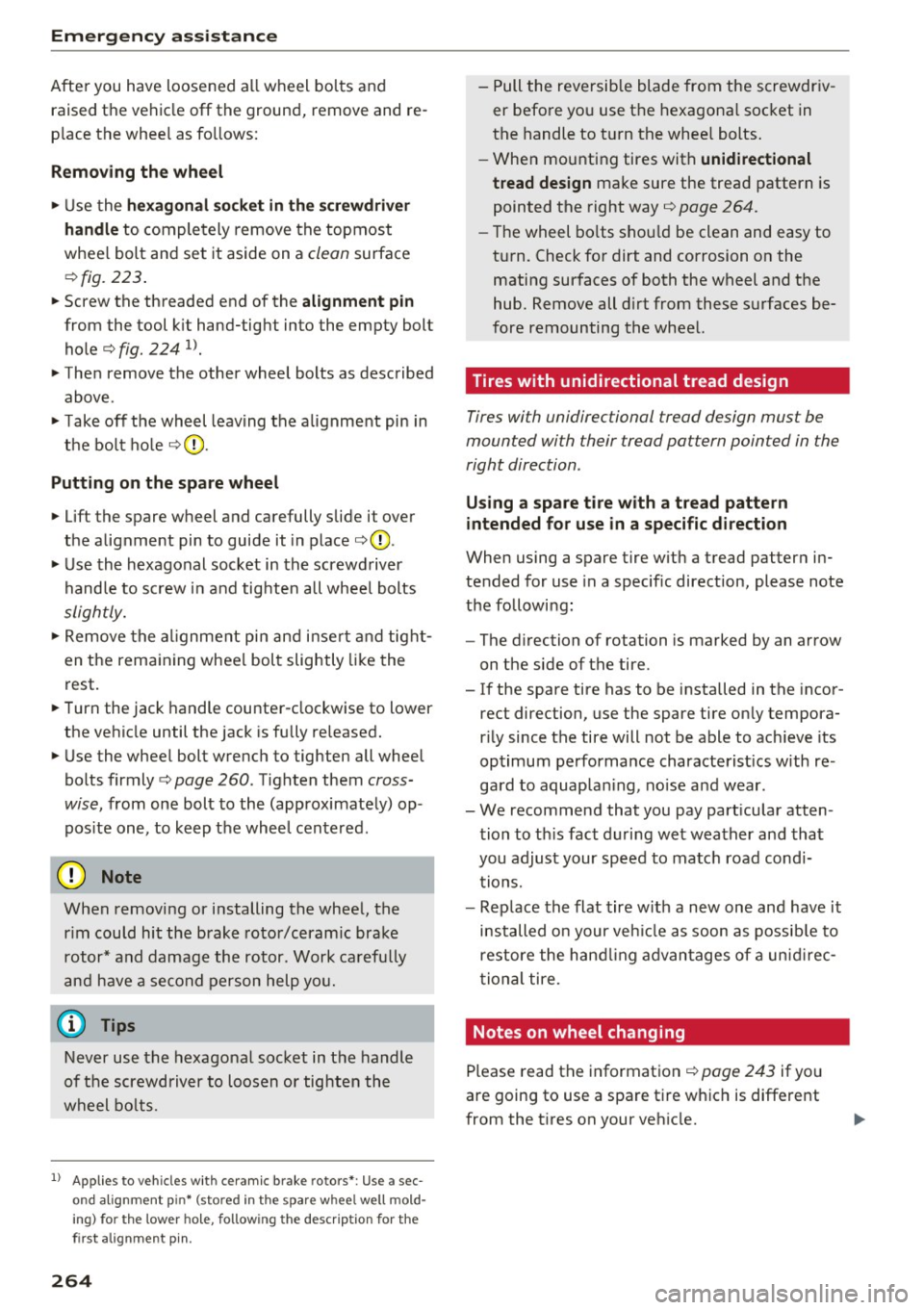
Fig . 223 Cha ngin g a w heel: us ing the screwdriver handle
(wit h the b lade removed) to turn th e bolts
Fig. 224 Changing a w hee l: a lig nment p in in side the top
hole
263
Page 266 of 302
Emergency assistance
After you have loosened all wheel bolts and raised the vehicle off the ground, remove and re
place the wheel as follows:
Removing the wheel
.,. Use the hexagonal socket in the screwdriver
handle
to completely remove the topmost
wheel bolt and set it aside on a
clean surface
.::!> fig. 223.
.,. Screw the threaded end of the alignment pin
from the tool kit hand-tight into the empty bolt
hole¢
fig. 224 1> .
.,. Then remove the other wheel bolts as described
above.
.,. Take off the wheel leaving the alignment pin in
the bolt hole ¢0 .
Putting on the spare wheel
.,. Lift the spare wheel and carefully slide it over
the alignment pin to guide it in place ¢0 .
.,. Use the hexagonal socket in the screwdriver
handle to screw in and tighten all wheel bolts
slightly .
.,. Remove the alignment pin and insert and tight
en the remaining wheel bolt slightly like the
rest.
.,. Turn the jack handle counter-clockwise to lower
the vehicle until the jack is fully released.
.,. Use the wheel bolt wrench to tighten all wheel
bolts firmly ¢
page 260 . Tighten them cross
wise,
from one bolt to the (approximately) op
posite one, to keep the wheel centered.
0 Note
When removing or installing the wheel, the
rim could hit the brake rotor/ceramic brake
rotor* and damage the rotor . Work carefully
and have a second person help you.
Never use the hexagonal socket in the handle
of the screwdriver to loosen or tighten the
wheel bolts.
1
> A pp lies to vehicles with cer amic brake rotors*: Use a sec
o n d alignment p in* (sto re d in th e s pare w hee l well mold
in g) fo r the lower hole , fol low ing the descrip tion for the
fir st a lig nme nt pin .
264
-Pull the reversible blade from the screwdriv
er before you use the hexagonal socket in
the handle to turn the wheel bolts.
- When mounting tires with
unidirectional
tread design
make sure the tread pattern is
pointed the right way¢
page 264.
-The wheel bolts should be clean and easy to
turn. Check for dirt and corrosion on the
mating surfaces of both the wheel and the
hub. Remove all dirt from these surfaces be
fore remounting the wheel.
Tires with unidirectional tread design
Tires with unidirectional tread design mus t be
mounted with their tread pattern pointed in the
right direction .
Using a spare tire with a tread pattern
intended for use in a specific direction
When using a spare tire with a tread pattern in
tended for use in a specific direction, please note
the following:
- The direction of rotation is marked by an arrow
on the side of the tire.
- If the spare tire has to be installed in the incor
rect direction, use the spare tire only tempora
rily since the tire will not be able to achieve its
optimum performance characteristics with re
gard to aquaplaning, noise and wear.
- We recommend that you pay particular atten
tion to this fact during wet weather and that
you adjust your speed to match road condi tions.
- Replace the flat tire with a new one and have it
installed on your vehicle as soon as possible to
restore the handling advantages of a unidirec
tional tire.
Notes on wheel changing
Please read the information¢ page 243 if you
are going to use a spare tire which is different
from the tires on your vehicle.
Page 267 of 302
After you change a tire:
- Check the tire pressure on the spare immedi
ately after in stallation.
- Have the wheel bolt tightening torque
checked with a torque wrench as soon as pos
s ible by your authorized Audi dealer or a
qualified servi ce stat ion .
- With steel and alloy wheel rims, the wheel
bolts are correctly tightened at a torque of 90
ft lb (120 Nm).
- If you notice that the wheel bolt s are corroded
and difficult to turn while changing a tire,
they should be replaced before you check the
tightening torque .
- Replace the flat tire with a new one and have
it installed on you r vehicle as soon as possi
ble. Remount the wheel cover .
Until then, drive with extra care and at reduced
speeds.
& WARNING
- If you are going to equ ip your vehi cle w it h
t ir es o r rims which differ f rom those which
we re factory installed, then be s ure to read
the info rmat io n ¢
page 243.
- Always ma ke sure the damaged whee l or
even a flat tire and the jack and tool kit a re
prope rly secured in the luggage com part
me nt and are not loose in t he passenger
compar tment.
- In an accident o r sudden maneuver they
cou ld fly forward, inju ring anyone in the ve
hicle.
- Always store damaged whee l, jac k and too ls
sec urely in the luggage co mpartment . Oth
erwise, in an accide nt or sudd en man euver
they could fly fo rw ar d, ca usin g injury to p as
sengers i n the vehicle .
-
Emergency assistance
265
Page 268 of 302
Fuses and bulbs
Fuses and bulbs
Fuses
Replacing fuses
A fuse that has blown will have me tal strips that
have burned through .
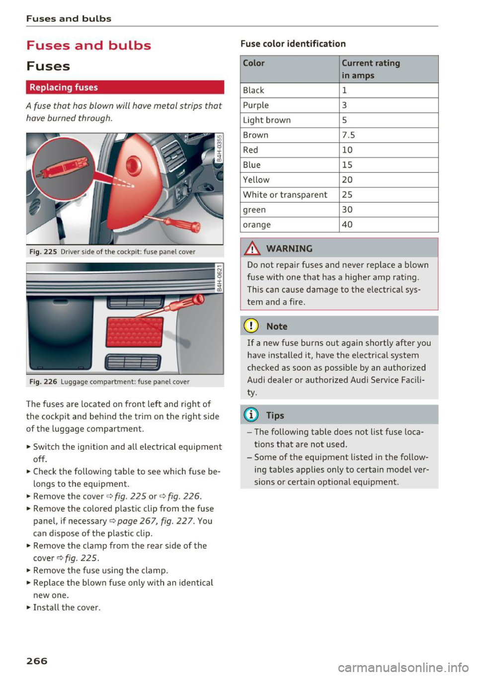
Fig. 2 25 Driver s ide of th e cockp it: fuse pa nel cover
I l I
Fig. 2 26 Lu ggage compartment: fuse pane l cover
The fuses are loca ted on front left and r igh t of
the cockpit and behind the trim on the right side
of the luggage compartment.
.. Swi tch the ignition and all e lec trica l equipment
off.
.. Check the following table to see which fuse be
lo ngs to the equipment .
.. Remove the cover c::> fig. 225 or
c:> fig. 226 .
.. Remove the colored plastic clip from the fuse
panel, if necessary
c:> page 267, fig. 22 7. You
can d ispose of the p lastic clip .
.. Remove the clamp from the rear s ide of the
cove rc::> fig. 225 .
.. Remove the f use usi ng the clamp .
.. Re place the b low n fu se only wi th an identi cal
new one .
.. Install the cover.
266 Fuse color identification
Color Current rating
in amps
Black 1
P urple 3
Light brown 5
Brown 7.5
Red 10
Blue 15
Yellow 20
Wh ite or transpa re nt 2 5
green 30
orange 40
A WARNING
-
Do not repair fuses and never replace a blown
f u se with one that has a highe r amp rat ing.
This ca n cause damage to t he e lectr ica l sys
tem and a fire.
(D Note
If a new fuse burns out again sho rtly after you
h ave insta lled it, have the electrical system
checked as soon as possible by an authorized
A udi dealer or authorized Aud i Service Fac ili
ty .
(D Tips
-The following table does not list fuse loca
tions that are no t used .
- Some of the equipment listed in the fo llow
ing tables applies on ly to certai n model ver
sions or certa in optional equipment .
Page 269 of 302
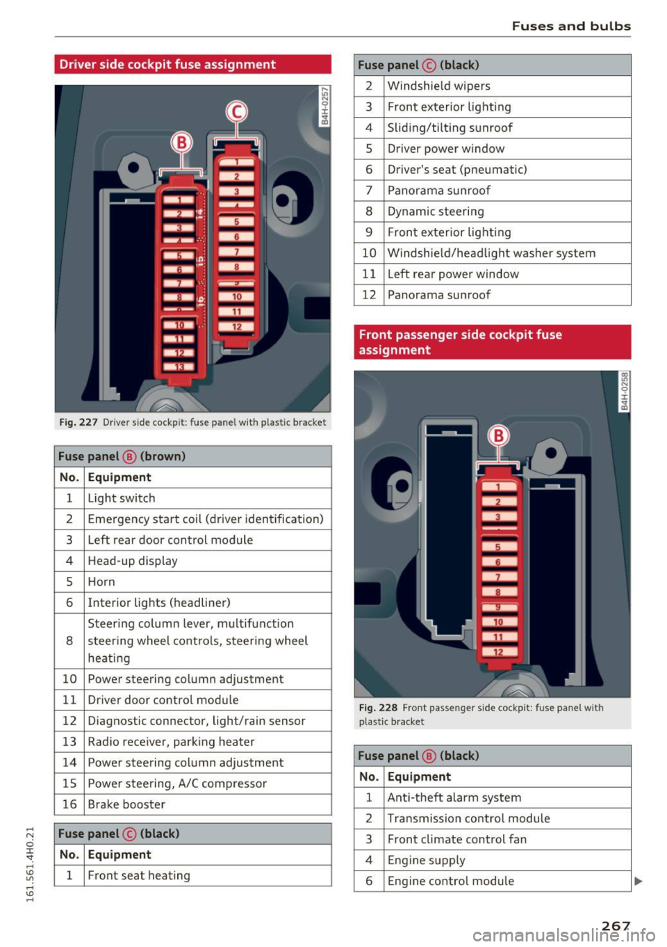
Driver side cockpit fuse assignment
Fig . 227 D river sid e cockpit: fuse panel with plastic bracket
Fuse panel @ (brown )
No . Equipment
1 Light switch
2 Emergency start coil (driver iden tification)
3 Left rear door con trol module
4 Head -up display
5 Ho rn
6 Interior lights (headliner)
Steering column lever, m ultifunction
8 steer ing whee l cont ro ls, steering wheel
heati ng
10 Powe r steering column adjustment
1 1 Dr iver door co ntro l mod ule
12 Diagnostic con nector, light/rain sensor
13 Radio rece iver, par king heater
14 Power steering column adjustment
15 Powe r stee ring, A/C comp resso r
16 Brake booster
Fuse panel © (black)
No . Equipment
1 Front seat heating
Fuses and bulbs
Fuse panel © (black)
2 Windshie ld w ipers
3 F ron t ex terior lig hti ng
4 Sliding/tilting s unroof
5 Dr iver power w indow
6 Driver's seat (pneumatic)
7 Pano rama su nroo f
8 Dynam ic steering
9 F ron t ex terior lig hting
10 W indshie ld/head light washer system
11 Left rea r powe r window
12 Panorama su nroof
Front passenger side cockpit fuse
assignment
Fig. 228 Front passenge r side cockp it: fuse panel with
p last ic b racket
Fuse panel @ (black)
No . Equipment
1 Ant i-theft alarm system
2 Transmission contro l modu le
3 Front climate control fan
4 Engine supply
6 Engine control module
267
Page 270 of 302

Fuses and bulbs
Fuse panel @ (black) Fuse panel@ (black)
7 Front passenger door contro l module
10 ESC contro
l modu le
8 Front passenger powe r window 11 Righ t rear power window
9 ESC control module 12 Front passenger
's seat (pneumatic)
Luggage compartment fuse assignment
F ig. 22 9 lu ggage compartment: fu se pane l wit h plastic bracket
Fuse panel @ (black) Fuse panel@ (black)
No. Equipment
1 ESC b
utton, dat a logge r, d iagnos tic con-
necto r, B CM -1, ad apt ive lig ht 10
Rear
seat heating, refrigerator, rearview
mirror
1 1 E lectrome chanical s teer ing
2 Networking gateway
12 Se
lector lever, BCM-2 voltage
3 ad aptive a ir suspension 13 Side assis t
4 Park ing system 14 Engine contro l module
5 Steeri
ng column lever
15 S
tarter
6 Suspension contro
l system sensor
7 Belt tensioners, airbag cont rol mod ule 16
Left
headlight (headl ights w it h adapt ive
li ght)/headlight range co ntrol
Heated washer fluid nozzles, Home link
8 (garage doo r opener), night vision system
cont rol module, sport differe ntia l, ioni ze r
9
Electromechan ica l park ing brake control
mod ule
Fuse panel ® (red)
No. Equipment
1 L
eft reve rsible belt tensioner
2 R ight revers ible belt tens ioner
268