ignition AUDI TT 1995 8N / 1.G ATW Engine Additional Signals Workshop Manual
[x] Cancel search | Manufacturer: AUDI, Model Year: 1995, Model line: TT, Model: AUDI TT 1995 8N / 1.GPages: 27, PDF Size: 0.12 MB
Page 5 of 27
24-159
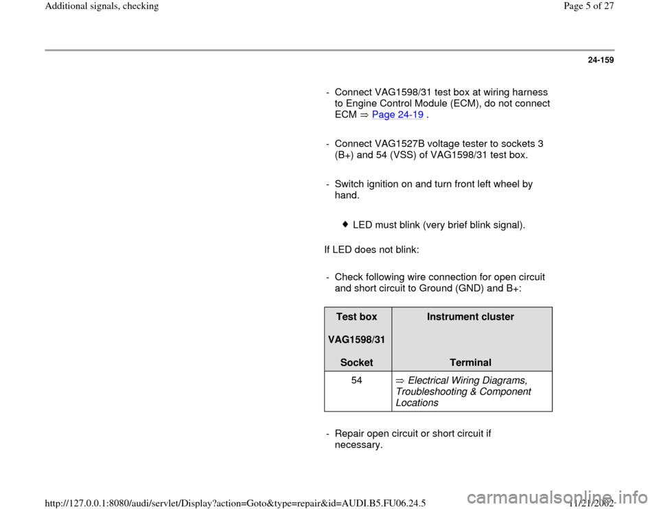
- Connect VAG1598/31 test box at wiring harness
to Engine Control Module (ECM), do not connect
ECM Page 24
-19
.
- Connect VAG1527B voltage tester to sockets 3
(B+) and 54 (VSS) of VAG1598/31 test box.
- Switch ignition on and turn front left wheel by
hand.
LED must blink (very brief blink signal).
If LED does not blink:
- Check following wire connection for open circuit
and short circuit to Ground (GND) and B+:
Test box
VAG1598/31
Socket
Instrument cluster
Terminal
54 Electrical Wiring Diagrams,
Troubleshooting & Component
Locations
- Repair open circuit or short circuit if
necessary.
Pa
ge 5 of 27 Additional si
gnals, checkin
g
11/21/2002 htt
p://127.0.0.1:8080/audi/servlet/Dis
play?action=Goto&t
yp
e=re
pair&id=AUDI.B5.FU06.24.5
Page 17 of 27
24-168
Test requirement:
Control module coding OK Page 01
-62
.
Test sequence
- Switch ignition off.
- Connect VAG1598/31 test box at wiring harness
to Engine Control Module (ECM), do not connect
ECM Page 24
-19
.
- Check following wire connection for open circuit
and short circuit to Ground (GND) and B+:
Test box
VAG1598/31
Socket
ABS control module (w/EDL)
-J104-
Terminal
74 Electrical Wiring Diagrams,
Troubleshooting & Component
Locations
If no malfunctions are found in wire:
- Replace ABS control module.
Pa
ge 17 of 27 Additional si
gnals, checkin
g
11/21/2002 htt
p://127.0.0.1:8080/audi/servlet/Dis
play?action=Goto&t
yp
e=re
pair&id=AUDI.B5.FU06.24.5
Page 19 of 27
24-169
Data transfer between Engine Control
Module (ECM) and CAN-capable control
modules, checking
Note:
Data exchange between individual control
modules occurs via a bus system.
The term "CAN-bus" refers to a system that
transports and distributes data.
The wire connections between the control
modules, via which data is transferred, are
referred to as data wires.
Data is transferred to the connected control
modules serially (one after the other) via these
data wires (i.e. engine speed, accelerator
position).
Checking bus system
The DTC table suggested checking the data
exchange between the Engine Control Module
(ECM) and CAN capable control modules.
-
Connect VAS5051 tester or VAG1551 scan tool
and select control module for engine electronics
using "address word" 01 Page 01
-10
. Ignition
Pa
ge 19 of 27 Additional si
gnals, checkin
g
11/21/2002 htt
p://127.0.0.1:8080/audi/servlet/Dis
play?action=Goto&t
yp
e=re
pair&id=AUDI.B5.FU06.24.5
Page 24 of 27
24-173
Example 1:
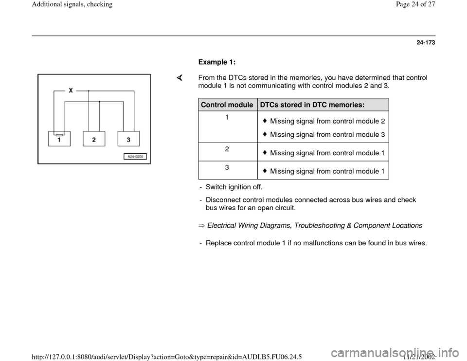
From the DTCs stored in the memories, you have determined that control
module 1 is not communicating with control modules 2 and 3.
Electrical Wiring Diagrams, Troubleshooting & Component Locations Control module
DTCs stored in DTC memories:
1
Missing signal from control module 2Missing signal from control module 3
2 Missing signal from control module 1
3 Missing signal from control module 1
- Switch ignition off.
- Disconnect control modules connected across bus wires and check
bus wires for an open circuit. - Replace control module 1 if no malfunctions can be found in bus wires.
Pa
ge 24 of 27 Additional si
gnals, checkin
g
11/21/2002 htt
p://127.0.0.1:8080/audi/servlet/Dis
play?action=Goto&t
yp
e=re
pair&id=AUDI.B5.FU06.24.5
Page 25 of 27
24-174
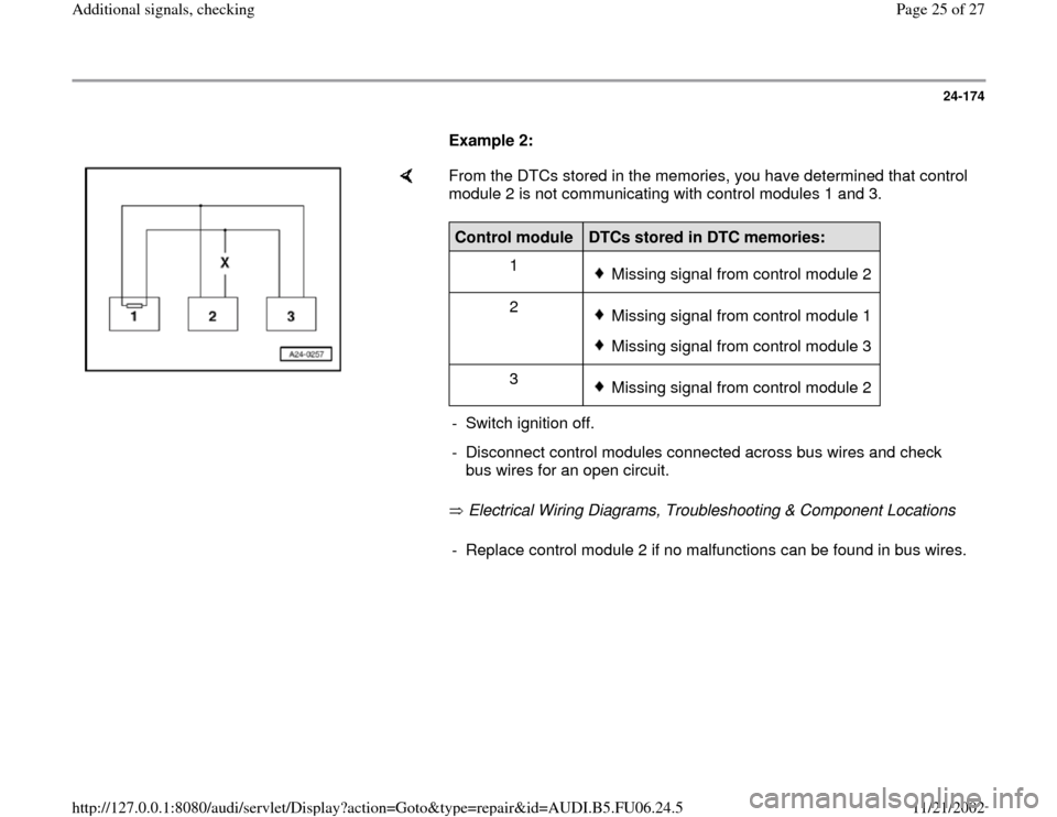
Example 2:
From the DTCs stored in the memories, you have determined that control
module 2 is not communicating with control modules 1 and 3.
Electrical Wiring Diagrams, Troubleshooting & Component Locations Control module
DTCs stored in DTC memories:
1
Missing signal from control module 2
2 Missing signal from control module 1Missing signal from control module 3
3 Missing signal from control module 2
- Switch ignition off.
- Disconnect control modules connected across bus wires and check
bus wires for an open circuit. - Replace control module 2 if no malfunctions can be found in bus wires.
Pa
ge 25 of 27 Additional si
gnals, checkin
g
11/21/2002 htt
p://127.0.0.1:8080/audi/servlet/Dis
play?action=Goto&t
yp
e=re
pair&id=AUDI.B5.FU06.24.5
Page 26 of 27
24-175
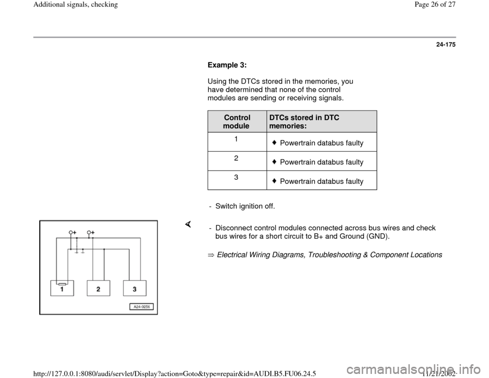
Example 3:
Using the DTCs stored in the memories, you
have determined that none of the control
modules are sending or receiving signals.
Control
module
DTCs stored in DTC
memories:
1
Powertrain databus faulty
2 Powertrain databus faulty
3 Powertrain databus faulty
- Switch ignition off.
Electrical Wiring Diagrams, Troubleshooting & Component Locations - Disconnect control modules connected across bus wires and check
bus wires for a short circuit to B+ and Ground (GND).
Pa
ge 26 of 27 Additional si
gnals, checkin
g
11/21/2002 htt
p://127.0.0.1:8080/audi/servlet/Dis
play?action=Goto&t
yp
e=re
pair&id=AUDI.B5.FU06.24.5
Page 27 of 27
24-176
If you cannot determine a cause for the DTC
"Powertrain databus malfunction, check
whether the DTC is caused by one of the
control modules.
All control modules that use the CAN-bus are still
disconnected. Ignition is switched off.
- Connect one control module.
- Connect VAG 1551 scan tool. Switch ignition on,
and erase DTC memory of control module just
connected. End scan tool output using "End
Output" function 06.
- Switch ignition off and then on.
- Leave ignition on for 10 seconds. Read DTC
memory of control module just connected.
- If DTC "Powertrain databus malfunction" is
displayed, replace control module just
connected.
- If DTC "Powertrain databus malfunction" is not
displayed, connect next control module and
repeat procedure.
Pa
ge 27 of 27 Additional si
gnals, checkin
g
11/21/2002 htt
p://127.0.0.1:8080/audi/servlet/Dis
play?action=Goto&t
yp
e=re
pair&id=AUDI.B5.FU06.24.5