lock AUDI TT 1997 8N / 1.G AEB ATW Engines Engine Assembly Workshop Manual
[x] Cancel search | Manufacturer: AUDI, Model Year: 1997, Model line: TT, Model: AUDI TT 1997 8N / 1.GPages: 38, PDF Size: 0.74 MB
Page 1 of 38
13-1
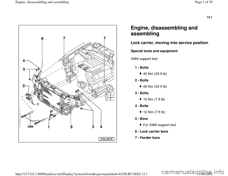
Engine, disassembling and
assembling Lock carrier, moving into service position
Special tools and equipment
3369 support tool
1 -
Bolts
45 Nm (33 ft lb)
2 -
Bolts 45 Nm (33 ft lb)
3 -
Bolts 10 Nm (7 ft lb)
4 -
Bolts 10 Nm (7 ft lb)
5 -
Bore For 3369 support tool
6 -
Lock carrier bore
7 -
Fender bore
Pa
ge 1 of 38 En
gine, disassemblin
g and assemblin
g
11/18/2002 htt
p://127.0.0.1:8080/audi/servlet/Dis
play?action=Goto&t
yp
e=re
pair&id=AUDI.B5.GE02.13.1
Page 2 of 38

13-2
Repair Manual, Body Exterior, Repair Group 63
- Remove front bumper.
- Remove 3 quick-release screws on front of noise
insulation panel.
- Unbolt air guide between lock carrier and air filter
at lock carrier.
- If installed, remove retaining clamps for wiring
harness on left side of radiator frame.
- Remove bolt -2- and install 3369 support tool.
- Install 3369 support tool into left bore -5-.
- Remove bolts -1- and -3-.
- Remove bolts -4- and pull lock carrier out to
stop.
- To secure lock carrier, install appropriate M6
bolts into rear bored holes of lock carrier -6- and
fender -7-.
Pa
ge 2 of 38 En
gine, disassemblin
g and assemblin
g
11/18/2002 htt
p://127.0.0.1:8080/audi/servlet/Dis
play?action=Goto&t
yp
e=re
pair&id=AUDI.B5.GE02.13.1
Page 3 of 38
13-3
Repair Manual, Body Exterior, Repair Group 63
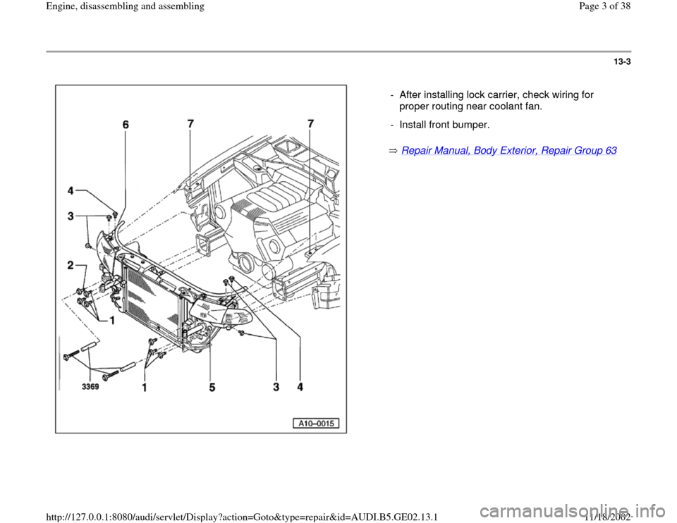
- After installing lock carrier, check wiring for
proper routing near coolant fan.
- Install front bumper.
Pa
ge 3 of 38 En
gine, disassemblin
g and assemblin
g
11/18/2002 htt
p://127.0.0.1:8080/audi/servlet/Dis
play?action=Goto&t
yp
e=re
pair&id=AUDI.B5.GE02.13.1
Page 7 of 38
13-7
Note:
For easier installation of generator into the bracket,
push back lower bolt bushing slightly. 17 -
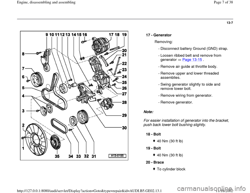
Generator
Removing:
- Disconnect battery Ground (GND) strap.
- Loosen ribbed belt and remove from
generator Page 13
-15
.
- Remove air guide at throttle body.
- Remove upper and lower threaded
assemblies.
- Swing generator slightly to side and
remove lower bolt.
- Remove wiring from generator.
- Remove generator.
18 -
Bolt
40 Nm (30 ft lb)
19 -
Bolt 40 Nm (30 ft lb)
20 -
Brace To cylinder block
Pa
ge 7 of 38 En
gine, disassemblin
g and assemblin
g
11/18/2002 htt
p://127.0.0.1:8080/audi/servlet/Dis
play?action=Goto&t
yp
e=re
pair&id=AUDI.B5.GE02.13.1
Page 16 of 38

13-14
Fig. 1 Viscous fan, removing and installing
Lock carrier in service position Page 13
-1
Ribbed belt free of tension Page 13
-15
- Secure belt pulley for viscous fan with 5 x 60 mm bolt and remove
using hex socket wrench.
- Remove viscous fan.
- When installing viscous fan, tighten to 45 Nm (33 ft lb).
Installation is only possible in one position: the bore hole of the vibration
damper (arrow) must align with raised portion of toothed belt gear. Fig. 2 Install vibration damper
Lock carrier in service position Page 13
-1
Ribbed belt removed Page 13
-15
- Install vibration damper using only original equipment bolts (bolt
strength grade 10.9) parts catalog. - Tighten vibration damper bolts to 40 Nm (30 ft lb).
Pa
ge 16 of 38 En
gine, disassemblin
g and assemblin
g
11/18/2002 htt
p://127.0.0.1:8080/audi/servlet/Dis
play?action=Goto&t
yp
e=re
pair&id=AUDI.B5.GE02.13.1
Page 17 of 38
13-15
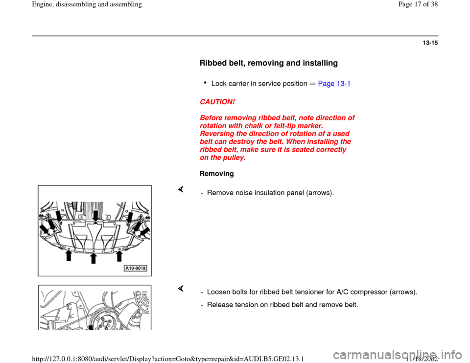
Ribbed belt, removing and installing
Lock carrier in service position Page 13
-1
CAUTION!
Before removing ribbed belt, note direction of
rotation with chalk or felt-tip marker.
Reversing the direction of rotation of a used
belt can destroy the belt. When installing the
ribbed belt, make sure it is seated correctly
on the pulley.
Removing
- Remove noise insulation panel (arrows).
- Loosen bolts for ribbed belt tensioner for A/C compressor (arrows).
- Release tension on ribbed belt and remove belt.
Pa
ge 17 of 38 En
gine, disassemblin
g and assemblin
g
11/18/2002 htt
p://127.0.0.1:8080/audi/servlet/Dis
play?action=Goto&t
yp
e=re
pair&id=AUDI.B5.GE02.13.1
Page 18 of 38
13-16
All models
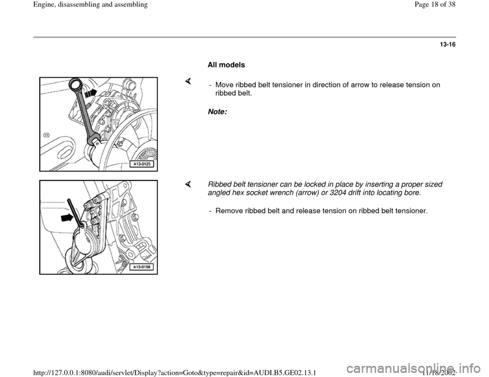
Note: - Move ribbed belt tensioner in direction of arrow to release tension on
ribbed belt.
Ribbed belt tensioner can be locked in place by inserting a proper sized
angled hex socket wrench (arrow) or 3204 drift into locating bore.
- Remove ribbed belt and release tension on ribbed belt tensioner.
Pa
ge 18 of 38 En
gine, disassemblin
g and assemblin
g
11/18/2002 htt
p://127.0.0.1:8080/audi/servlet/Dis
play?action=Goto&t
yp
e=re
pair&id=AUDI.B5.GE02.13.1
Page 20 of 38
13-18
V-belt, removing and installing
Lock carrier in service position Page 13
-
17
Ribbed belt free of tension Page 13
-15
Removing
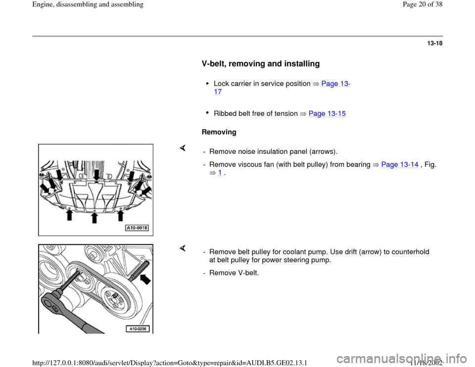
- Remove noise insulation panel (arrows).
- Remove viscous fan (with belt pulley) from bearing Page 13
-14
, Fig.
1
.
- Remove belt pulley for coolant pump. Use drift (arrow) to counterhold
at belt pulley for power steering pump.
- Remove V-belt.
Pa
ge 20 of 38 En
gine, disassemblin
g and assemblin
g
11/18/2002 htt
p://127.0.0.1:8080/audi/servlet/Dis
play?action=Goto&t
yp
e=re
pair&id=AUDI.B5.GE02.13.1
Page 22 of 38
13-20
Bearing for viscous fan in mounting
bracket, removing and installing
Lock carrier in service position Page 13
-1
Special tools and equipment
Hex nut from 3301 assembly tool
Extractor pipe from 3350 installation device
3367 press out tool for viscous clutch fan
bearing bushing
Removing
- Remove ribbed belt Page 13
-15
.
- Remove viscous fan (together with belt pulley)
Page 13
-14
, Fig. 1
.
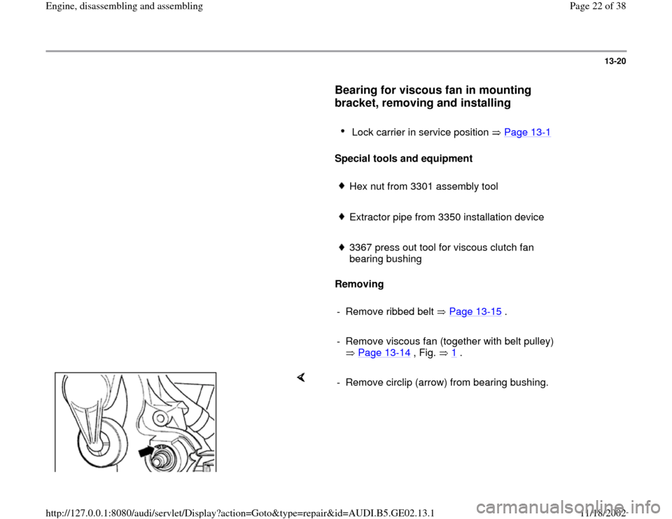
- Remove circlip (arrow) from bearing bushing.
Pa
ge 22 of 38 En
gine, disassemblin
g and assemblin
g
11/18/2002 htt
p://127.0.0.1:8080/audi/servlet/Dis
play?action=Goto&t
yp
e=re
pair&id=AUDI.B5.GE02.13.1
Page 24 of 38
13-22
Mounting bracket for generator, power
steering pump and viscous fan,
removing and installing
Lock carrier in service position Page 13
-1
Removing
CAUTION!
Before disconnecting the battery, determine
the correct coding for the anti-theft radio.
Note:
Ribbed belt for A/C remains installed.
Ribbed belt, removing Page 13
-15
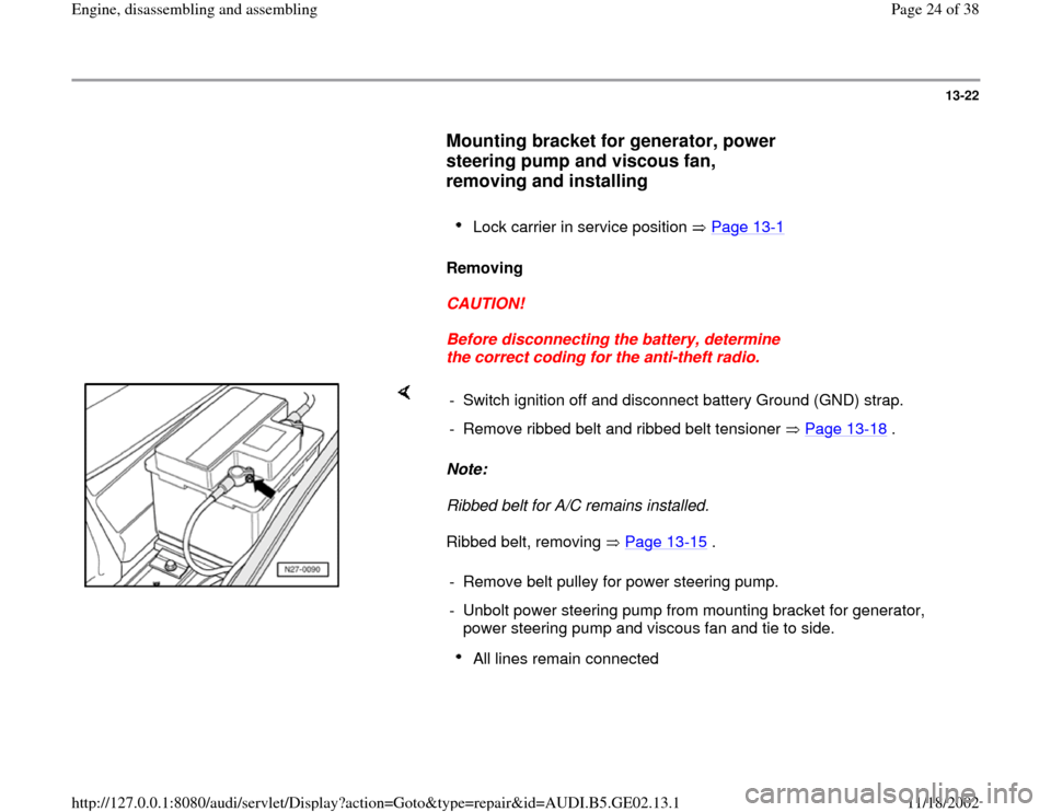
. - Switch ignition off and disconnect battery Ground (GND) strap.
- Remove ribbed belt and ribbed belt tensioner Page 13
-18
.
- Remove belt pulley for power steering pump.
- Unbolt power steering pump from mounting bracket for generator,
power steering pump and viscous fan and tie to side.
All lines remain connected
Pa
ge 24 of 38 En
gine, disassemblin
g and assemblin
g
11/18/2002 htt
p://127.0.0.1:8080/audi/servlet/Dis
play?action=Goto&t
yp
e=re
pair&id=AUDI.B5.GE02.13.1