wiring AUDI TT 1997 8N / 1.G AEB ATW Engines Secondary Air System Workshop Manual
[x] Cancel search | Manufacturer: AUDI, Model Year: 1997, Model line: TT, Model: AUDI TT 1997 8N / 1.GPages: 16, PDF Size: 0.21 MB
Page 8 of 16
26-36
Electrical Wiring Diagrams, Troubleshooting & Component Locations
Repair Manual, Fuel Supply System, Repair Group 20
Checking activation
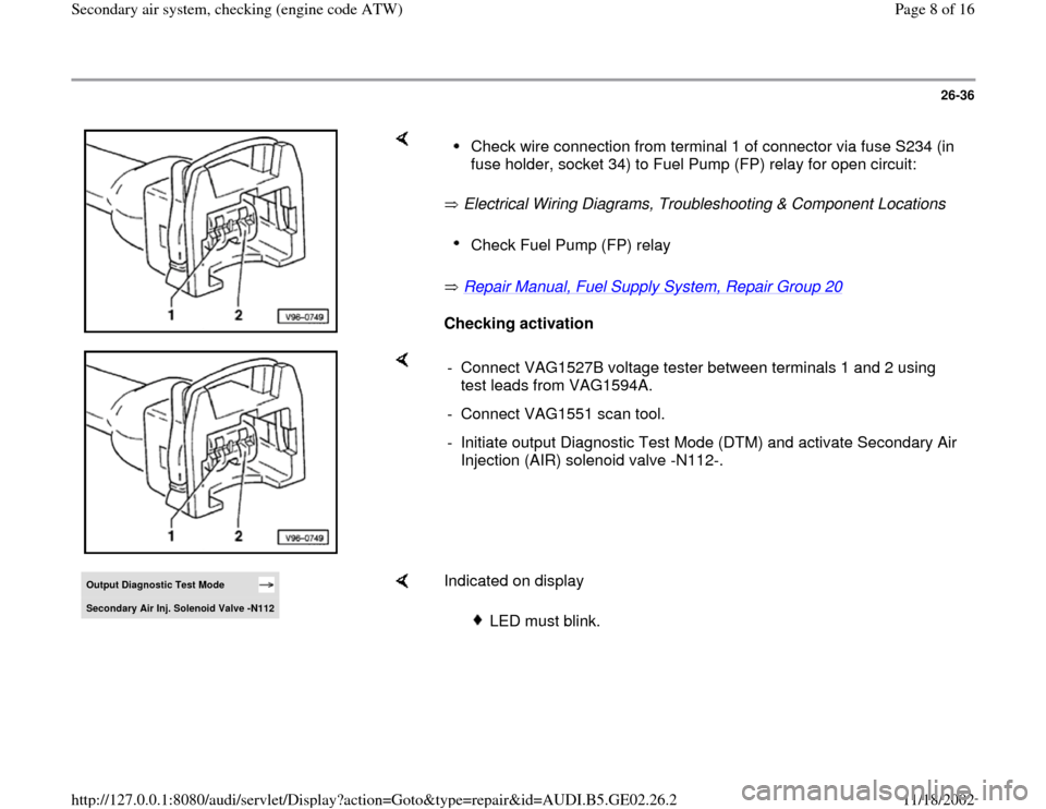
Check wire connection from terminal 1 of connector via fuse S234 (in
fuse holder, socket 34) to Fuel Pump (FP) relay for open circuit: Check Fuel Pump (FP) relay
- Connect VAG1527B voltage tester between terminals 1 and 2 using
test leads from VAG1594A.
- Connect VAG1551 scan tool.
- Initiate output Diagnostic Test Mode (DTM) and activate Secondary Air
Injection (AIR) solenoid valve -N112-.
Output Diagnostic Test Mode Secondary Air Inj. Solenoid Valve -N112
Indicated on display
LED must blink.
Pa
ge 8 of 16 Secondar
y air s
ystem, checkin
g (en
gine code ATW
)
11/18/2002 htt
p://127.0.0.1:8080/audi/servlet/Dis
play?action=Goto&t
yp
e=re
pair&id=AUDI.B5.GE02.26.2
Page 9 of 16
26-37
If LED does not blink or if it remains constantly
lit:
- Connect VAG1598/31 test box at wiring harness
to ECM, do not connect ECM.
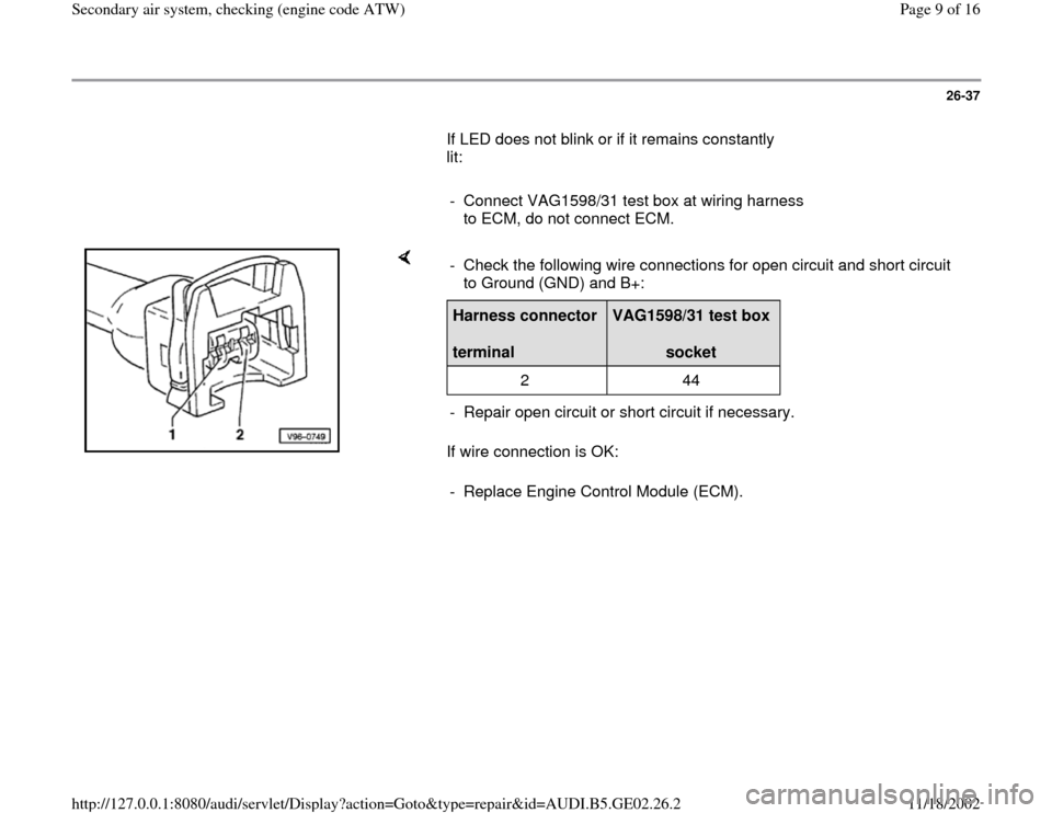
If wire connection is OK: - Check the following wire connections for open circuit and short circuit
to Ground (GND) and B+: Harness connector
terminal
VAG1598/31 test box
socket
2 44
- Repair open circuit or short circuit if necessary.
- Replace Engine Control Module (ECM).
Pa
ge 9 of 16 Secondar
y air s
ystem, checkin
g (en
gine code ATW
)
11/18/2002 htt
p://127.0.0.1:8080/audi/servlet/Dis
play?action=Goto&t
yp
e=re
pair&id=AUDI.B5.GE02.26.2
Page 12 of 16
26-40
Checking voltage supply of Secondary Air
Injection (AIR) pump relay
- Remove Secondary Air Injection (AIR) pump
relay.
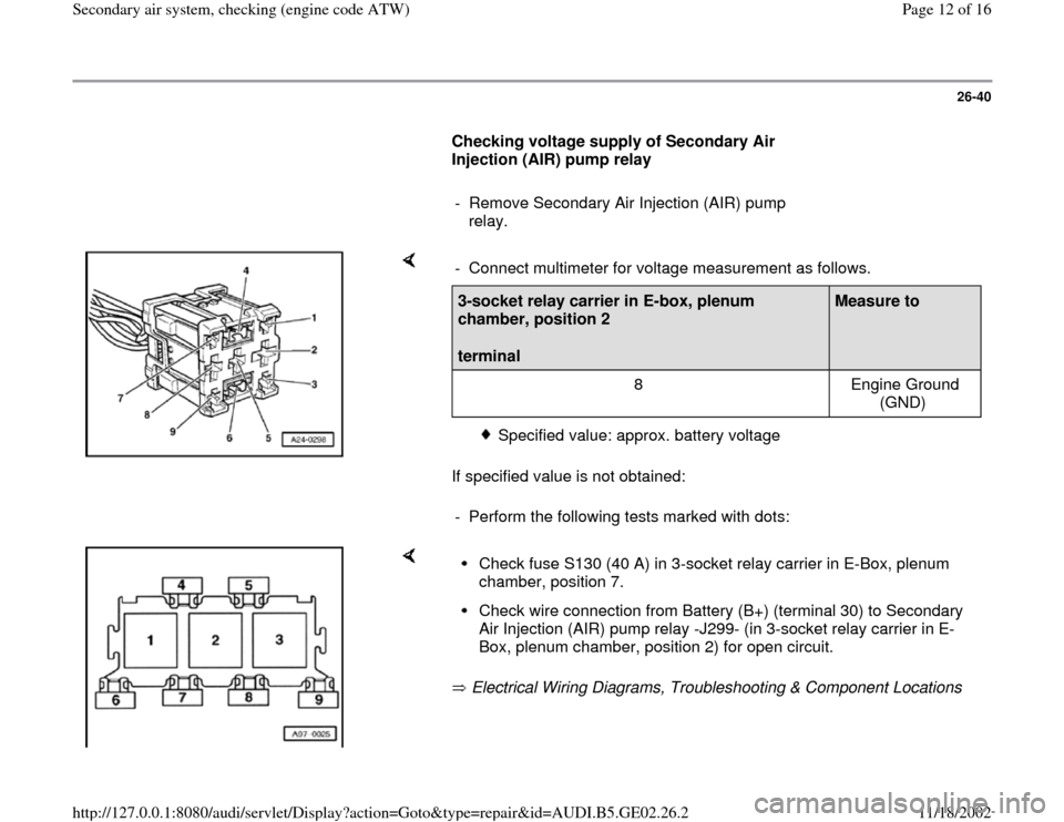
If specified value is not obtained: - Connect multimeter for voltage measurement as follows.3-socket relay carrier in E-box, plenum
chamber, position 2
terminal
Measure to
8 Engine Ground
(GND)
Specified value: approx. battery voltage
- Perform the following tests marked with dots:
Electrical Wiring Diagrams, Troubleshooting & Component Locations Check fuse S130 (40 A) in 3-socket relay carrier in E-Box, plenum
chamber, position 7. Check wire connection from Battery (B+) (terminal 30) to Secondary
Air Injection (AIR) pump relay -J299- (in 3-socket relay carrier in E-
Box, plenum chamber, position 2) for open circuit.
Pa
ge 12 of 16 Secondar
y air s
ystem, checkin
g (en
gine code ATW
)
11/18/2002 htt
p://127.0.0.1:8080/audi/servlet/Dis
play?action=Goto&t
yp
e=re
pair&id=AUDI.B5.GE02.26.2
Page 13 of 16
26-41
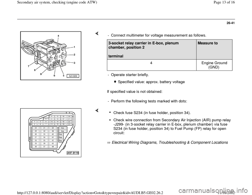
If specified value is not obtained: - Connect multimeter for voltage measurement as follows.3-socket relay carrier in E-box, plenum
chamber, position 2
terminal
Measure to
4 Engine Ground
(GND)
- Operate starter briefly.
Specified value: approx. battery voltage
- Perform the following tests marked with dots:
Electrical Wiring Diagrams, Troubleshooting & Component Locations Check fuse S234 (in fuse holder, position 34). Check wire connection from Secondary Air Injection (AIR) pump relay
-J299- (in 3-socket relay carrier in E-box, plenum chamber) via fuse
S234 (in fuse holder, position 34) to Fuel Pump (FP) relay for open
circuit:
Pa
ge 13 of 16 Secondar
y air s
ystem, checkin
g (en
gine code ATW
)
11/18/2002 htt
p://127.0.0.1:8080/audi/servlet/Dis
play?action=Goto&t
yp
e=re
pair&id=AUDI.B5.GE02.26.2
Page 14 of 16
26-42
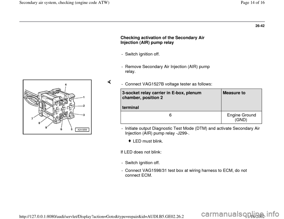
Checking activation of the Secondary Air
Injection (AIR) pump relay
- Switch ignition off.
- Remove Secondary Air Injection (AIR) pump
relay.
If LED does not blink: - Connect VAG1527B voltage tester as follows:3-socket relay carrier in E-box, plenum
chamber, position 2
terminal
Measure to
6 Engine Ground
(GND)
- Initiate output Diagnostic Test Mode (DTM) and activate Secondary Air
Injection (AIR) pump relay -J299-.
LED must blink.
- Switch ignition off.
- Connect VAG1598/31 test box at wiring harness to ECM, do not
connect ECM.
Pa
ge 14 of 16 Secondar
y air s
ystem, checkin
g (en
gine code ATW
)
11/18/2002 htt
p://127.0.0.1:8080/audi/servlet/Dis
play?action=Goto&t
yp
e=re
pair&id=AUDI.B5.GE02.26.2
Page 16 of 16
26-44
If LED does not light:
- Perform the following tests marked with dots:
Check wire connection from harness
connector at Secondary Air Injection (AIR)
pump motor -V101- to Secondary Air
Injection (AIR) pump relay -J299- (in 3-
socket relay carrier in E-Box, plenum
chamber, position 2) for open circuit.
Electrical Wiring Diagrams, Troubleshooting &
Component Locations
Check wire connection from harness
connector at Secondary Air Injection (AIR)
pump motor -V101- to Ground (GND)
connection 1 in engine compartment wiring
harness for open circuit:
Electrical Wiring Diagrams, Troubleshooting &
Component Locations
If no malfunctions are detected:
- Replace Secondary Air Injection (AIR) pump
motor -V101-.
Pa
ge 16 of 16 Secondar
y air s
ystem, checkin
g (en
gine code ATW
)
11/18/2002 htt
p://127.0.0.1:8080/audi/servlet/Dis
play?action=Goto&t
yp
e=re
pair&id=AUDI.B5.GE02.26.2