fold AUDI TT 1997 8N / 1.G ATW Engine Motronic Fuel Injection Syst
[x] Cancel search | Manufacturer: AUDI, Model Year: 1997, Model line: TT, Model: AUDI TT 1997 8N / 1.GPages: 81, PDF Size: 1.03 MB
Page 15 of 81
24-14
Note:
In order to assure sufficiently secure fitting, switches must not be installed
more than once.
Adjusting switch:
Repair Manual, Brake System, Repair Group 46, Brake booster, removing and installing
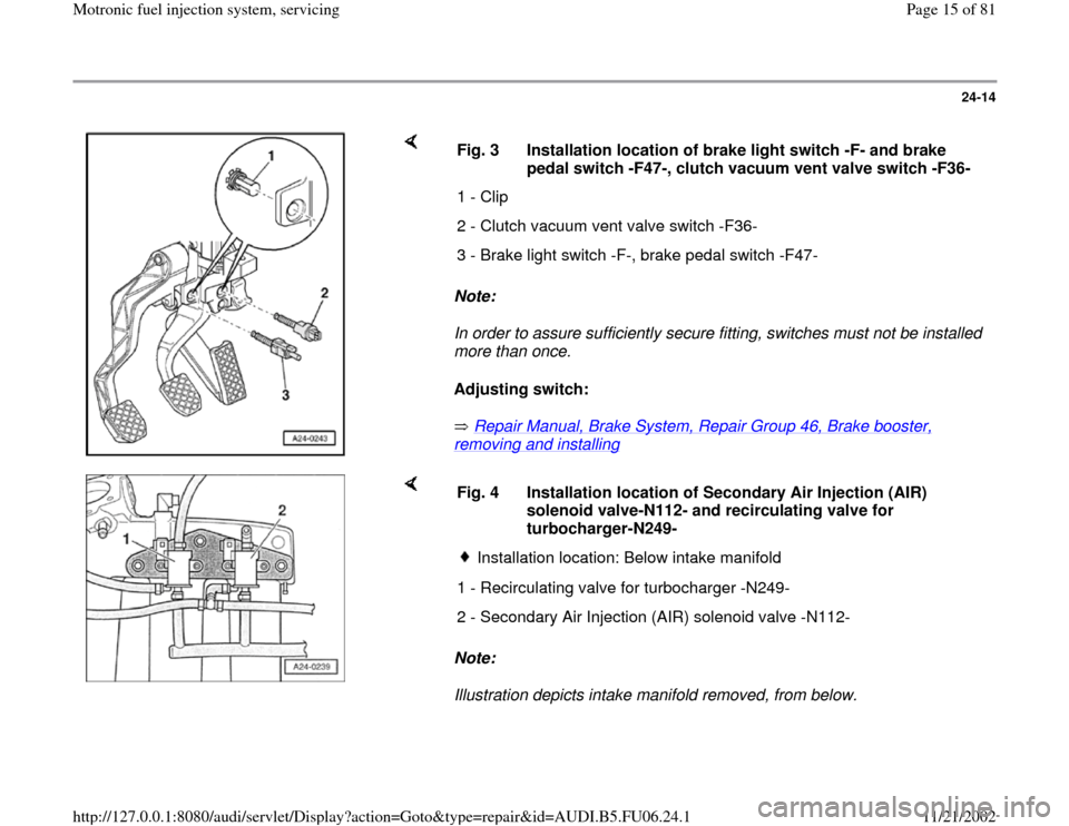
Fig. 3 Installation location of brake light switch -F- and brake
pedal switch -F47-, clutch vacuum vent valve switch -F36-
1 - Clip
2 - Clutch vacuum vent valve switch -F36-
3 - Brake light switch -F-, brake pedal switch -F47-
Note:
Illustration depicts intake manifold removed, from below. Fig. 4 Installation location of Secondary Air Injection (AIR)
solenoid valve-N112- and recirculating valve for
turbocharger-N249-
Installation location: Below intake manifold
1 - Recirculating valve for turbocharger -N249-
2 - Secondary Air Injection (AIR) solenoid valve -N112-
Pa
ge 15 of 81 Motronic fuel in
jection s
ystem, servicin
g
11/21/2002 htt
p://127.0.0.1:8080/audi/servlet/Dis
play?action=Goto&t
yp
e=re
pair&id=AUDI.B5.FU06.24.1
Page 37 of 81
24-33
System pressure, fuel pressure
regulator and residual pressure,
checking
Note:
Fuel pressure regulator regulates fuel pressure
according to intake manifold pressure. This
ensures that the pressure drop at the fuel
injectors remains the same for each speed and
load range of the engine.
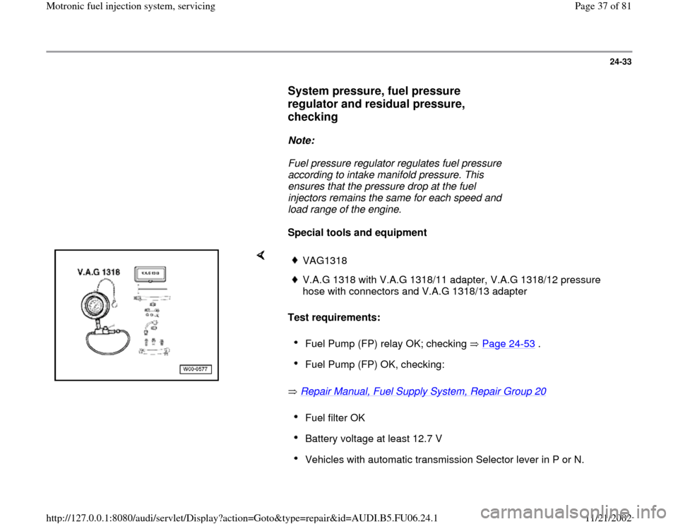
Special tools and equipment
Test requirements:
Repair Manual, Fuel Supply System, Repair Group 20
VAG1318V.A.G 1318 with V.A.G 1318/11 adapter, V.A.G 1318/12 pressure
hose with connectors and V.A.G 1318/13 adapter Fuel Pump (FP) relay OK; checking Page 24
-53
.
Fuel Pump (FP) OK, checking: Fuel filter OK Battery voltage at least 12.7 V Vehicles with automatic transmission Selector lever in P or N.
Pa
ge 37 of 81 Motronic fuel in
jection s
ystem, servicin
g
11/21/2002 htt
p://127.0.0.1:8080/audi/servlet/Dis
play?action=Goto&t
yp
e=re
pair&id=AUDI.B5.FU06.24.1
Page 50 of 81
24-45
Repair Manual, 1.8 Liter 4
-Cyl. 5V Turbo Engine
Mechanical, Engine Code(s): AEB, ATW, Repair Group 15; Cylinder head, removing and installing; Intake manifold, removing and installing
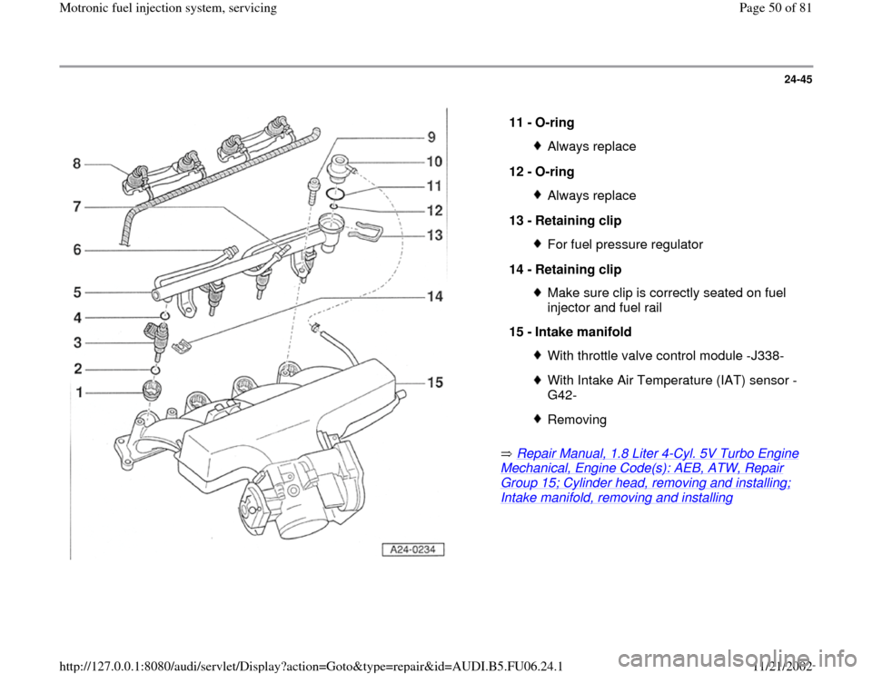
11 -
O-ring
Always replace
12 -
O-ring Always replace
13 -
Retaining clip For fuel pressure regulator
14 -
Retaining clip Make sure clip is correctly seated on fuel
injector and fuel rail
15 -
Intake manifold With throttle valve control module -J338-With Intake Air Temperature (IAT) sensor -
G42- Removing
Pa
ge 50 of 81 Motronic fuel in
jection s
ystem, servicin
g
11/21/2002 htt
p://127.0.0.1:8080/audi/servlet/Dis
play?action=Goto&t
yp
e=re
pair&id=AUDI.B5.FU06.24.1
Page 53 of 81
24-48
Make sure fuel injectors are in place and
seated correctly
Check clip for unobstructed fitting.
Place fuel rail with secured fuel injectors
onto intake manifold, and apply uniform
pressure to press it in.
Tightening torque
Component
Nm
Fuel distributor at intake manifold 10
Pa
ge 53 of 81 Motronic fuel in
jection s
ystem, servicin
g
11/21/2002 htt
p://127.0.0.1:8080/audi/servlet/Dis
play?action=Goto&t
yp
e=re
pair&id=AUDI.B5.FU06.24.1
Page 55 of 81
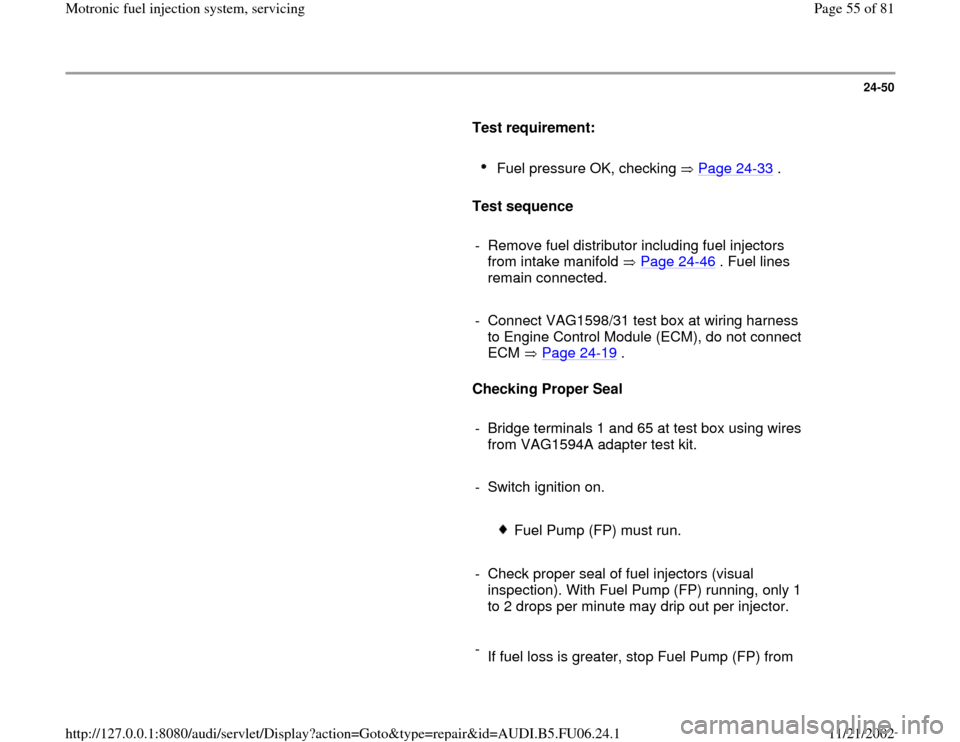
24-50
Test requirement:
Fuel pressure OK, checking Page 24
-33
.
Test sequence
- Remove fuel distributor including fuel injectors
from intake manifold Page 24
-46
. Fuel lines
remain connected.
- Connect VAG1598/31 test box at wiring harness
to Engine Control Module (ECM), do not connect
ECM Page 24
-19
.
Checking Proper Seal
- Bridge terminals 1 and 65 at test box using wires
from VAG1594A adapter test kit.
- Switch ignition on.
Fuel Pump (FP) must run.
- Check proper seal of fuel injectors (visual
inspection). With Fuel Pump (FP) running, only 1
to 2 drops per minute may drip out per injector.
-
If fuel loss is greater, stop Fuel Pump (FP) from
Pa
ge 55 of 81 Motronic fuel in
jection s
ystem, servicin
g
11/21/2002 htt
p://127.0.0.1:8080/audi/servlet/Dis
play?action=Goto&t
yp
e=re
pair&id=AUDI.B5.FU06.24.1
Page 73 of 81
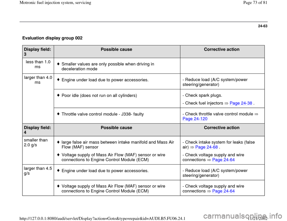
24-63
Evaluation display group 002 Display field:
3
Possible cause
Corrective action
less than 1.0
ms
Smaller values are only possible when driving in
deceleration mode
larger than 4.0
ms Engine under load due to power accessories.- Reduce load (A/C system/power
steering/generator)
Poor idle (does not run on all cylinders)- Check spark plugs.
- Check fuel injectors Page 24
-38
.
Throttle valve control module - J338- faulty- Check throttle valve control module
Page 24
-120
Display field:
4
Possible cause
Corrective action
smaller than
2.0 g/s
large false air mass between intake manifold and Mass Air
Flow (MAF) sensor
Voltage supply of Mass Air Flow (MAF) sensor or wire
connections to Engine Control Module (ECM) - Check intake system for leaks (false
air) Page 24
-68
.
- Check voltage supply and wire
connections Page 24
-64
larger than 4.5
g/s
Engine under load due to power accessories.- Reduce load (A/C system/power
steering/generator)
Voltage supply of Mass Air Flow (MAF) sensor or wire
connections to Engine Control Module (ECM) - Check voltage supply and wire
connections Page 24
-64
Pa
ge 73 of 81 Motronic fuel in
jection s
ystem, servicin
g
11/21/2002 htt
p://127.0.0.1:8080/audi/servlet/Dis
play?action=Goto&t
yp
e=re
pair&id=AUDI.B5.FU06.24.1