AUDI TT 2000 8N / 1.G ATW Engine Motronic Fuel Injection Syst
Manufacturer: AUDI, Model Year: 2000,
Model line: TT,
Model: AUDI TT 2000 8N / 1.G
Pages: 81, PDF Size: 1.03 MB
AUDI TT 2000 8N / 1.G ATW Engine Motronic Fuel Injection Syst
TT 2000 8N / 1.G
AUDI
AUDI
https://www.carmanualsonline.info/img/6/1078/w960_1078-0.png
AUDI TT 2000 8N / 1.G ATW Engine Motronic Fuel Injection Syst
Trending: fuse box location, light, torque, wiring diagram, check engine light, oil pressure, fuses
Page 51 of 81
24-46
Fuel injectors, removing and installing
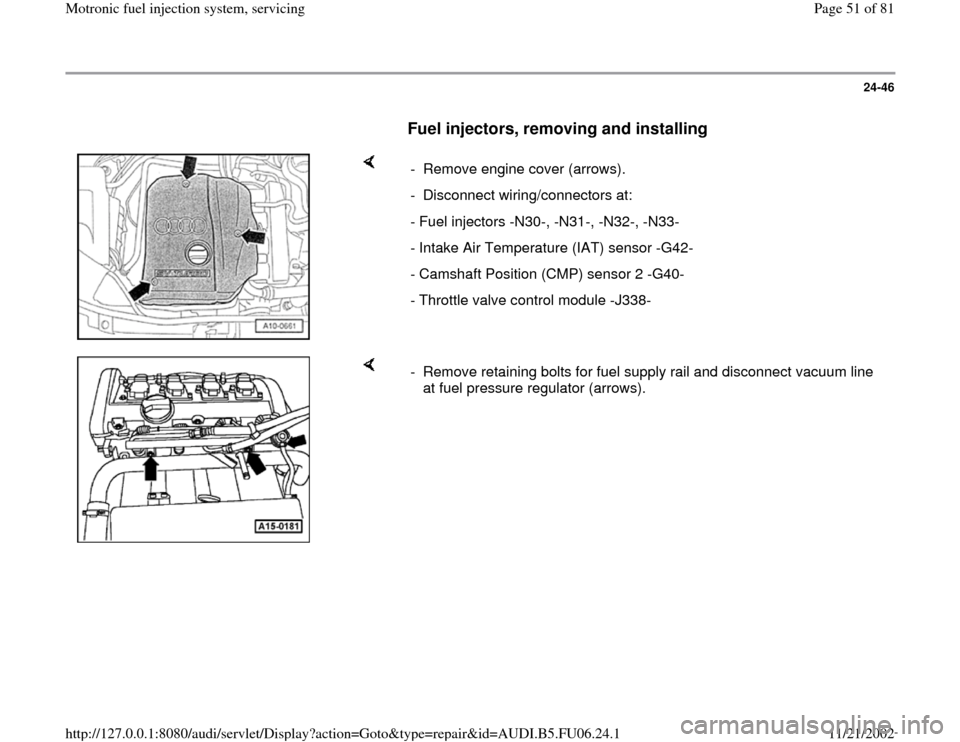
- Remove engine cover (arrows).
- Disconnect wiring/connectors at:
- Fuel injectors -N30-, -N31-, -N32-, -N33-
- Intake Air Temperature (IAT) sensor -G42-
- Camshaft Position (CMP) sensor 2 -G40-
- Throttle valve control module -J338-
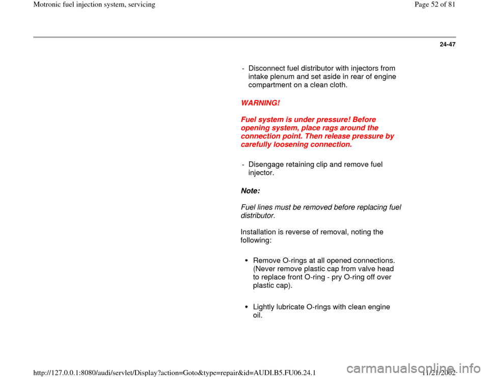
- Remove retaining bolts for fuel supply rail and disconnect vacuum line
at fuel pressure regulator (arrows).
Pa
ge 51 of 81 Motronic fuel in
jection s
ystem, servicin
g
11/21/2002 htt
p://127.0.0.1:8080/audi/servlet/Dis
play?action=Goto&t
yp
e=re
pair&id=AUDI.B5.FU06.24.1
Page 52 of 81
24-47
- Disconnect fuel distributor with injectors from
intake plenum and set aside in rear of engine
compartment on a clean cloth.
WARNING!
Fuel system is under pressure! Before
opening system, place rags around the
connection point. Then release pressure by
carefully loosening connection.
- Disengage retaining clip and remove fuel
injector.
Note:
Fuel lines must be removed before replacing fuel
distributor.
Installation is reverse of removal, noting the
following:
Remove O-rings at all opened connections.
(Never remove plastic cap from valve head
to replace front O-ring - pry O-ring off over
plastic cap).
Lightly lubricate O-rings with clean engine
oil.
Pa
ge 52 of 81 Motronic fuel in
jection s
ystem, servicin
g
11/21/2002 htt
p://127.0.0.1:8080/audi/servlet/Dis
play?action=Goto&t
yp
e=re
pair&id=AUDI.B5.FU06.24.1
Page 53 of 81
24-48
Make sure fuel injectors are in place and
seated correctly
Check clip for unobstructed fitting.
Place fuel rail with secured fuel injectors
onto intake manifold, and apply uniform
pressure to press it in.
Tightening torque
Component
Nm
Fuel distributor at intake manifold 10
Pa
ge 53 of 81 Motronic fuel in
jection s
ystem, servicin
g
11/21/2002 htt
p://127.0.0.1:8080/audi/servlet/Dis
play?action=Goto&t
yp
e=re
pair&id=AUDI.B5.FU06.24.1
Page 54 of 81
24-49
Fuel injector injection quantity, proper
seal and spray pattern, checking
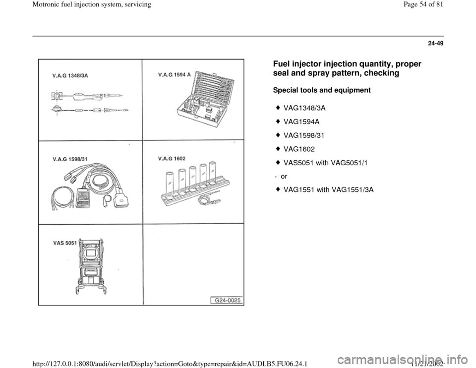
Special tools and equipment
VAG1348/3A
VAG1594A
VAG1598/31
VAG1602
VAS5051 with VAG5051/1
- or
VAG1551 with VAG1551/3A
Pa
ge 54 of 81 Motronic fuel in
jection s
ystem, servicin
g
11/21/2002 htt
p://127.0.0.1:8080/audi/servlet/Dis
play?action=Goto&t
yp
e=re
pair&id=AUDI.B5.FU06.24.1
Page 55 of 81
24-50
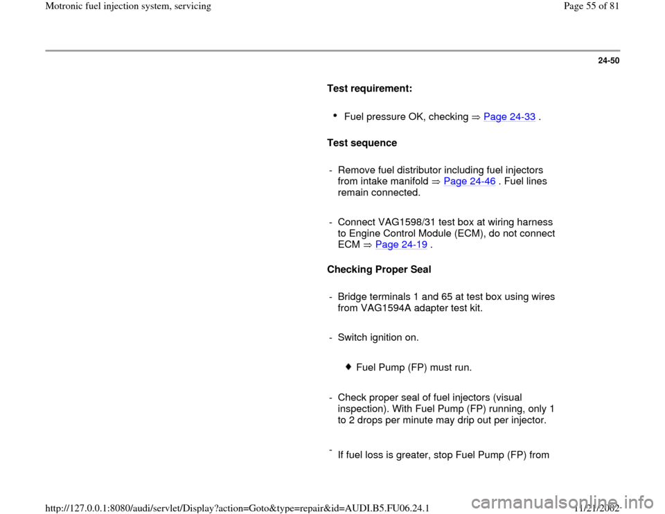
Test requirement:
Fuel pressure OK, checking Page 24
-33
.
Test sequence
- Remove fuel distributor including fuel injectors
from intake manifold Page 24
-46
. Fuel lines
remain connected.
- Connect VAG1598/31 test box at wiring harness
to Engine Control Module (ECM), do not connect
ECM Page 24
-19
.
Checking Proper Seal
- Bridge terminals 1 and 65 at test box using wires
from VAG1594A adapter test kit.
- Switch ignition on.
Fuel Pump (FP) must run.
- Check proper seal of fuel injectors (visual
inspection). With Fuel Pump (FP) running, only 1
to 2 drops per minute may drip out per injector.
-
If fuel loss is greater, stop Fuel Pump (FP) from
Pa
ge 55 of 81 Motronic fuel in
jection s
ystem, servicin
g
11/21/2002 htt
p://127.0.0.1:8080/audi/servlet/Dis
play?action=Goto&t
yp
e=re
pair&id=AUDI.B5.FU06.24.1
Page 56 of 81
running (switch off ignition) and replace faulty
fuel injector Page 24
-46
.
Pa
ge 56 of 81 Motronic fuel in
jection s
ystem, servicin
g
11/21/2002 htt
p://127.0.0.1:8080/audi/servlet/Dis
play?action=Goto&t
yp
e=re
pair&id=AUDI.B5.FU06.24.1
Page 57 of 81
24-51
Checking Injection Quantity
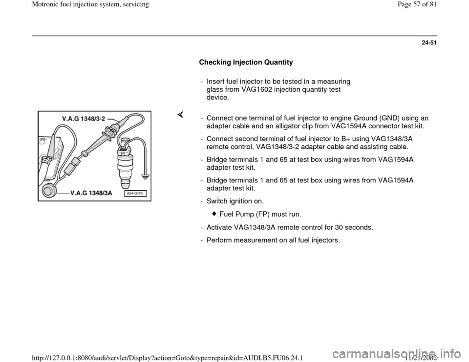
- Insert fuel injector to be tested in a measuring
glass from VAG1602 injection quantity test
device.
- Connect one terminal of fuel injector to engine Ground (GND) using an
adapter cable and an alligator clip from VAG1594A connector test kit.
- Connect second terminal of fuel injector to B+ using VAG1348/3A
remote control, VAG1348/3-2 adapter cable and assisting cable.
- Bridge terminals 1 and 65 at test box using wires from VAG1594A
adapter test kit.
- Bridge terminals 1 and 65 at test box using wires from VAG1594A
adapter test kit.
- Switch ignition on.
Fuel Pump (FP) must run.
- Activate VAG1348/3A remote control for 30 seconds.
- Perform measurement on all fuel injectors.
Pa
ge 57 of 81 Motronic fuel in
jection s
ystem, servicin
g
11/21/2002 htt
p://127.0.0.1:8080/audi/servlet/Dis
play?action=Goto&t
yp
e=re
pair&id=AUDI.B5.FU06.24.1
Page 58 of 81
24-52
- After all four fuel injectors have been activated,
place measuring glasses on an even surface.
Specified value for each fuel injector: 135
10 ml
- If measured value of one or more fuel injectors
is outside of specified range, switch Fuel Pump
(FP) off (switch ignition off) and replace faulty
fuel injector Page 24
-46
.
- If measured values of all fuel injectors are
outside specified range, check fuel pressure
Page 24
-33
.
Note:
Also check spray pattern when checking injection
quantity. Spray pattern must be the same for all
injectors
- Install fuel injectors together with fuel distributor
Page 24
-47
.
Pa
ge 58 of 81 Motronic fuel in
jection s
ystem, servicin
g
11/21/2002 htt
p://127.0.0.1:8080/audi/servlet/Dis
play?action=Goto&t
yp
e=re
pair&id=AUDI.B5.FU06.24.1
Page 59 of 81
24-53
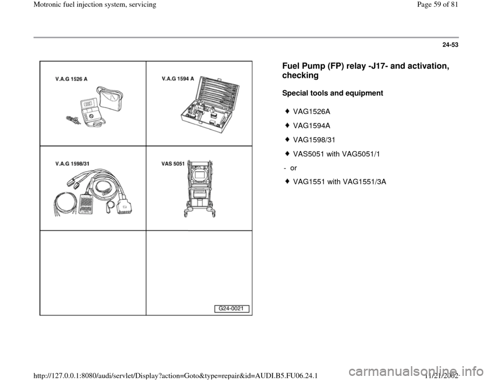
Fuel Pump (FP) relay -J17- and activation,
checking
Special tools and equipment
VAG1526A
VAG1594A
VAG1598/31
VAS5051 with VAG5051/1
- or
VAG1551 with VAG1551/3A
Pa
ge 59 of 81 Motronic fuel in
jection s
ystem, servicin
g
11/21/2002 htt
p://127.0.0.1:8080/audi/servlet/Dis
play?action=Goto&t
yp
e=re
pair&id=AUDI.B5.FU06.24.1
Page 60 of 81
24-54
Component location Overview of component
locations Page 24
-5 .
Voltage is supplied to the Fuel Pump (FP) and
several components of the injection system via
the Fuel Pump (FP) relay -J17-.
Engine must be turning for Fuel Pump (FP) relay
-J17- to close. This means that the relay does
not receive Ground (GND) (via ECM) until the
ECM recognizes RPM signals.
Test requirement:
Battery voltage at least 12.7 V
Function test of Fuel Pump (FP) relay
- Remove driver-side storage compartment.
Repair Manual, Body Interior, Repair Group
68
- Connect VAS5051 tester or VAG1551 scan tool
and select control module for engine electronics
using "address word" 01 Page 01
-10
. Ignition
must remain switched on.
-
Initiate output Diagnostic Test Mode (DTM)
Pa
ge 60 of 81 Motronic fuel in
jection s
ystem, servicin
g
11/21/2002 htt
p://127.0.0.1:8080/audi/servlet/Dis
play?action=Goto&t
yp
e=re
pair&id=AUDI.B5.FU06.24.1
Trending: air condition, fuse diagram, warning, warning light, wiring, airbag off, spark plugs
