diagram AUDI TT 2000 8N / 1.G ATW Engine Motronic Fuel Injection Syst
[x] Cancel search | Manufacturer: AUDI, Model Year: 2000, Model line: TT, Model: AUDI TT 2000 8N / 1.GPages: 81, PDF Size: 1.03 MB
Page 44 of 81
24-40
Checking voltage supply
Test requirements:
Fuse for fuel injectors OK
Electrical Wiring Diagrams, Troubleshooting &
Component Locations
Fuel Pump (FP) relay OK; checking Page 24
-53
.
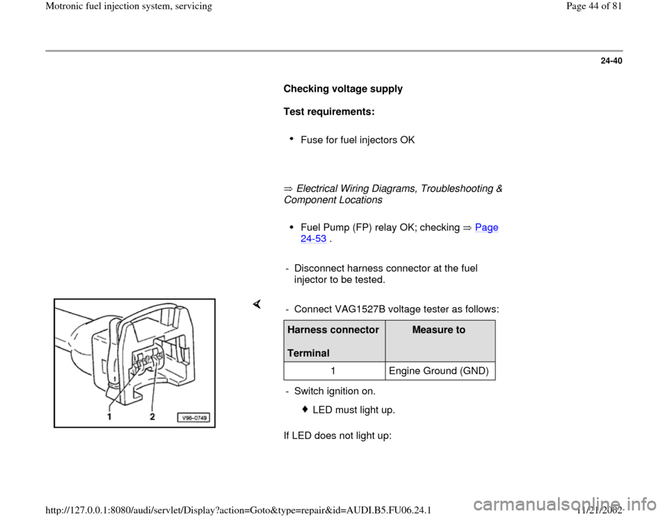
- Disconnect harness connector at the fuel
injector to be tested.
If LED does not light up: - Connect VAG1527B voltage tester as follows:Harness connector
Terminal
Measure to
1 Engine Ground (GND)
- Switch ignition on.
LED must light up.
Pa
ge 44 of 81 Motronic fuel in
jection s
ystem, servicin
g
11/21/2002 htt
p://127.0.0.1:8080/audi/servlet/Dis
play?action=Goto&t
yp
e=re
pair&id=AUDI.B5.FU06.24.1
Page 45 of 81
Electrical Wiring Diagrams, Troubleshooting & Component Locations - Check wire connection between terminal 1 and fuse for injector valves
for open circuit:
Pa
ge 45 of 81 Motronic fuel in
jection s
ystem, servicin
g
11/21/2002 htt
p://127.0.0.1:8080/audi/servlet/Dis
play?action=Goto&t
yp
e=re
pair&id=AUDI.B5.FU06.24.1
Page 65 of 81
24-57
If specified value is not obtained:
Electrical Wiring Diagrams, Troubleshooting & Component Locations
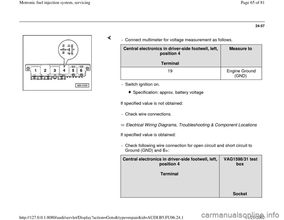
If specified value is obtained: - Connect multimeter for voltage measurement as follows.Central electronics in driver-side footwell, left,
position 4
Terminal
Measure to
19 Engine Ground
(GND)
- Switch ignition on.
Specification: approx. battery voltage
- Check wire connections.
- Check following wire connection for open circuit and short circuit to
Ground (GND) and B+: Central electronics in driver-side footwell, left,
position 4
Terminal
VAG1598/31 test
box
Socket
Pa
ge 65 of 81 Motronic fuel in
jection s
ystem, servicin
g
11/21/2002 htt
p://127.0.0.1:8080/audi/servlet/Dis
play?action=Goto&t
yp
e=re
pair&id=AUDI.B5.FU06.24.1
Page 68 of 81
24-59
If specified values are not obtained:
- Repeat test at another terminal of fuse socket.
If specified values are not obtained again:
- Check wire connections.
Electrical Wiring Diagrams, Troubleshooting &
Component Locations If no malfunctions are detected:
- Replace Fuel Pump (FP) relay -J17-.
- Re-insert fuses.
Pa
ge 68 of 81 Motronic fuel in
jection s
ystem, servicin
g
11/21/2002 htt
p://127.0.0.1:8080/audi/servlet/Dis
play?action=Goto&t
yp
e=re
pair&id=AUDI.B5.FU06.24.1
Page 74 of 81
24-64
Voltage supply for Mass Air Flow (MAF)
sensor, checking
Test requirements:
Fuse for Mass Air Flow (MAF) sensor OK
Electrical Wiring Diagrams, Troubleshooting &
Component Locations
Fuel Pump (FP) relay OK; checking Page 24
-53
.
Note:
Voltage is supplied to Mass Air Flow (MAF)
sensor from Fuel Pump (FP) relay.
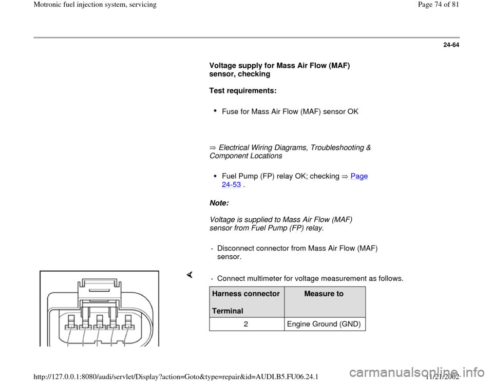
- Disconnect connector from Mass Air Flow (MAF)
sensor.
- Connect multimeter for voltage measurement as follows.Harness connector
Terminal
Measure to
2 Engine Ground (GND)
Pa
ge 74 of 81 Motronic fuel in
jection s
ystem, servicin
g
11/21/2002 htt
p://127.0.0.1:8080/audi/servlet/Dis
play?action=Goto&t
yp
e=re
pair&id=AUDI.B5.FU06.24.1
Page 76 of 81
24-65
If specified value is not obtained:
- Check wire connection from terminal 2 of
connector to Fuel Pump (FP) relay via fuse for
open circuit and short circuit to Ground (GND):
Electrical Wiring Diagrams, Troubleshooting &
Component Locations
- Repair open circuit or short circuit if
necessary.
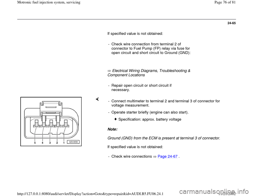
Note:
Ground (GND) from the ECM is present at terminal 3 of connector.
If specified value is not obtained: - Connect multimeter to terminal 2 and terminal 3 of connector for
voltage measurement.
- Operate starter briefly (engine can also start).
Specification: approx. battery voltage
- Check wire connections Page 24
-67
.
Pa
ge 76 of 81 Motronic fuel in
jection s
ystem, servicin
g
11/21/2002 htt
p://127.0.0.1:8080/audi/servlet/Dis
play?action=Goto&t
yp
e=re
pair&id=AUDI.B5.FU06.24.1