sensor AUDI TT 2013 Owner´s Manual
[x] Cancel search | Manufacturer: AUDI, Model Year: 2013, Model line: TT, Model: AUDI TT 2013Pages: 262, PDF Size: 65.91 MB
Page 134 of 262
132 Child Saf ety
seat. The weight of a child restraint and its
"footprint" vary for different kinds of chi ld re
straints and for the d ifferent models of the
same kind of child restraint offered by child
restra int manufacturers.
The weight ranges for the individual types,
makes and mode ls of ch ild restra ints that the
NHTSA has specified in the Safety Standard
together with the weight ranges of typical in
fants and typical 1 year-old child have been
stored in the control unit of the Advanced A ir
bag System. When a ch ild restrai nt is being
used on the front passenger seat with a typi
cal 1 yea r-old ch ild, the Advanced Airbag Sys
tem compares the we ight measured by the
weight sensing mat with the in formation stor
ed in the electronic control unit.
The ele ctron ic cont rol unit also registers the
tension on the front passenge r safety belt.
The tension on the safety be lt fo r the front
passenger seat will be different for an ad ult
who is properly using the safety belt as com
pared to the tension on the belt when it is
used to attach a child restraint to the seat.
The sensor below the latch for the safety belt
for the front seat passenger measu res the
tension on the be lt. The input from this sen
sor is then used with the we ight to "decide",
whe ther there is a ch ild restraint w ith a typ ica l
1 year-o ld child on the front passenger seat
and whether or not the airbag must be turned
off .
Child restraints and Advanced Airbags
Regardless of the child restraint that you use,
make sure that it has been certified to meet
United States Federal Motor Vehicle Safety
Standards a nd has been certified by its manu
facture r fo r u se w ith an airbag. Always be s ure
that t he ch ild res traint is p rope rly insta lled at
one o f th e rear seat ing pos itions. If in excep
tional c ircu mstances you must use it on the
front passenger seat, caref ully read all of the
info rmation on c hild safety and Advanced Air
bags and heed all of the applicable WARN
INGS. Make certain that the child restraint is
correctly recognized by the weig ht-sensing mat
inside the front passenger seat, that the
front passenger airbag is turned off and that
the a irbag stat us is always cor rect ly signa led
by the
PASSENGER AIR BAG OFF light.
Many types and models of child res traints
have been available over the years, new mod
els are introduced regu larly incorporating new
and improved des igns and older models are
taken out of product ion. Ch ild restraints are
not standard ized . Child restraints of the same
type typically have d ifferent weights and sizes
and diff erent 'footpr ints,' the s ize and shape
of the bo ttom of the ch ild restra int that sits
o n t he seat, when they a re inst alled on a vehi
cle sea t. Th ese d ifferences make it vir tually
impossible to certify compliance with the re
quirements for advanced airbags with eac h
and every child restra int that has ever been
sold in the past or will be sold over the course
of the useful life of your veh icle.
For th is reason, the United States National
Highway Traffic Safety Adm inistrat ion has
published a list of specific type, makes and
models of child restraints that must be used
to certify comp liance of the Advanced Airbag
System i n your veh icle w ith the suppression
requirements of Federal Motor Vehicle Safety
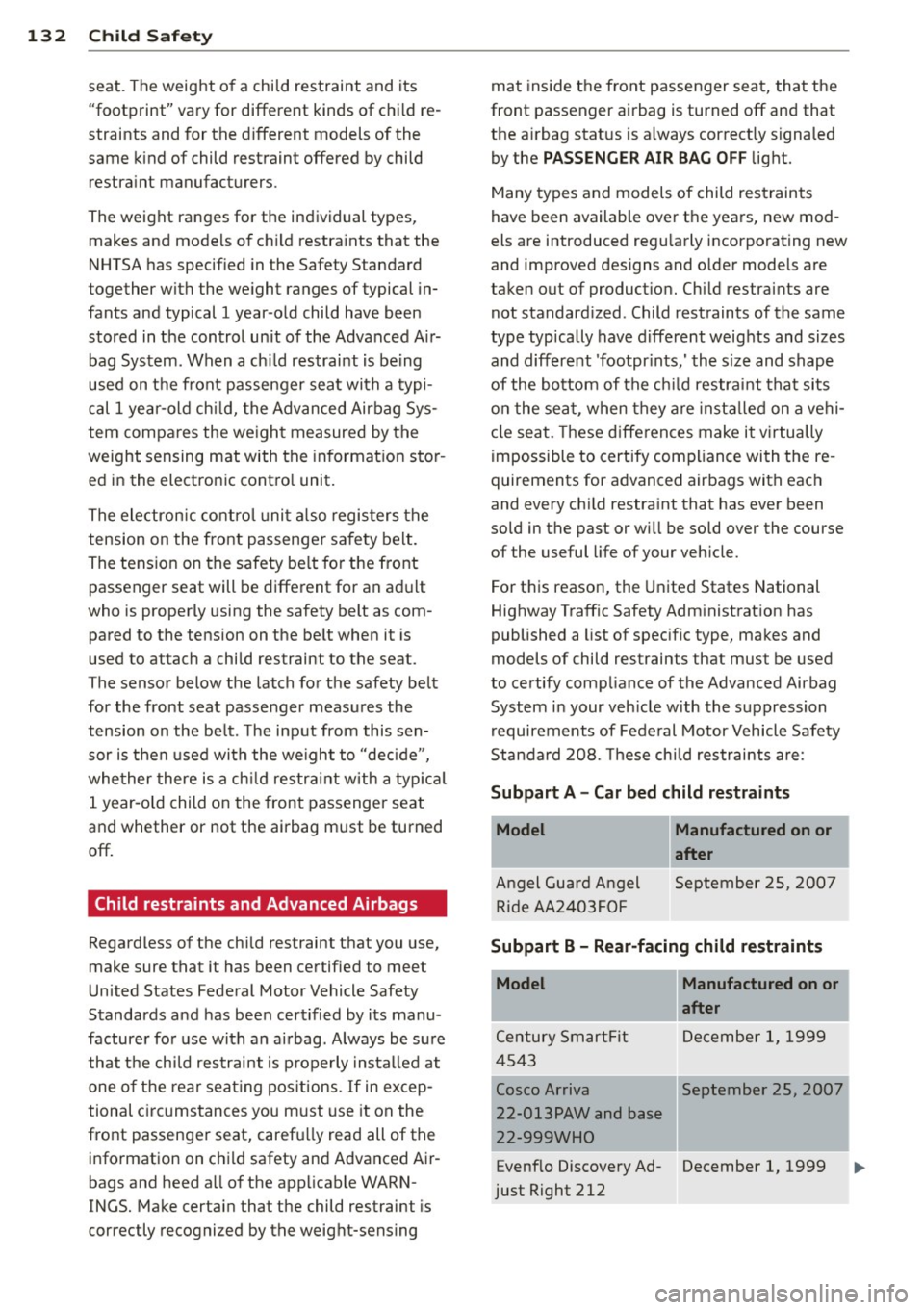
Standa rd 208. These chi ld restraints are:
Subpart A - Car bed child restraints
Model
Angel Guard Angel R ide AA 2403FOF
Manufactured on or
after
September 25, 200 7
Subpart B - Rear-facing child restraints
Model Manufactured on or
·
Century SmartFit
4543
Cosco Arriva
22-013PAW and base
22-999W HO
Evenf lo Discove ry Ad
just Right 212
after .
De cembe r 1, 1999
September 25, 2007
'
.
December 1, 1999 IJ>,
Page 158 of 262
156 Intellig ent technol ogy
Snow cha in s
Where t ire cha ins are mandatory on certain
roads, this normally a lso applies to vehicles
with a ll-wheel drive ¢
page 212, Snow
chains .
Replacing wheels /t ir es
Vehicles with all-wheel drive must a lways
have tires of the same size. Also avoid t ires
with different tread depths. For details see
page ~
page 207, New tires and replacing
tires and wheels.
Off -Ro ad dri ving?
Your Aud i does not have enough ground clear
ance to be used as an off -road veh icle.
It is
therefore best to avoid rough tracks and un
even terrain as much as possible . Also refer to
¢ page 160.
A WARNING
Always adjust your driving to road and traf
fic conditions. Do not let the extra safety
afforded by all-wheel dr ive tempt you into
taking extra r isks.
- Although the all-wheel dr ive is very ef
fective, always remember that braking capacity is limited by t ire traction . You
should the refore not dr ive at excessive
speeds on icy or slippery road su rfaces.
- On wet road surfaces, be careful not to
dr ive too fast because the front wheels
cou ld beg in to s lide on top of the wa ter
(aquaplaning) .
If this should occ ur, you
will have no warning from a sudden in
crease in engine speed as with a front
wheel drive vehicle. A lways drive at
speeds wh ich are suited to the road con
ditions. -risk of crash.
Energy management
Starting ability is optimized
Energy management controls the distribution
of electrical energy and thus optimizes the
availability of electrical energy for starting the engine.
If a vehicle with a conventional energy system
is not driven for a long per iod of t ime, the bat
tery is discharged by idling current consumers (e .g. immobilize r). In certa in circumstances it
can resu lt in the re be ing insufficient energy
available to start the engine.
Intelligent energy management in your vehi
cl e handles the distribution of e lectr ica l ene r
gy . Start ing ability is ma rkedly improved and
the life of the battery is extended .
Bas ica lly, energy management consists of
b att ery diag nosis, idlin g curre nt manage
m ent
and dynamic en erg y manag em ent .
Battery di agnosis
Battery diagnosis continuously determines
the state of the battery. Sensors determine
battery voltage, battery current and battery
temperature. This determines the current state o f charge and the power of the battery .
Idling current managem ent
Idling current management reduces energy
consumption while the vehicle is standing .
With the ig nition sw itched off, it controls the
energy supply to the various electri ca l compo
nents. Da ta from ba ttery diagnos is is cons id
ered.
Depend ing on the batte ry's state of cha rge,
individual cons ume rs a re g radually turned off
to prevent excessive discharge of the battery
and th us maintain starting capability.
Dynamic energ y manag ement
While the vehicle is being driven, dynamic en
ergy ma nagement distr ibutes the energy gen
era ted accord ing to t he needs of the individ u-
al components .
It regula tes consumption, so
that more electrical energy is not being used ..,.
Page 168 of 262
166 Cleaning and protection
sponges to prevent scratches. It is best
to use soapy water .
- You should remove debris (such as in
sects) from the headlight lenses on a
regular basis, for example when refuel
li ng your vehicle.
@ For the sake of the environment
On ly wash the vehicle in facilit ies specially
designed for that purpose. This w ill reduce
the risk of d irty water contaminated with
oil from entering the sewer system. In
some areas, washing vehicles outs ide of
these facilities is prohib ited.
Washing your vehicle with a power
washer
Cleaning the exterior of your car with a high
pressure power washer is safe as long as you
observe a few simple rules.
• Before using the power washe r, make sure
you have read and understood the WARN
I N GS 9 .&. in General information on
page 1 64.
• Always fo llow the opera ting ins truc tions for
the power washer.
• Make sure that the jet on the spray hose
produces a "fan shaped spray" .
• Do
no t ho ld the spray no zzle too close to
soft materia ls.
Keep a distance from soft materials such as
rubber hoses or insulat ing mater ial as we ll as
sensors and camera lenses.
When clea ning the vehicle wit h a power wash
er
always f o llow the operating instructions .
This applies particularly to the operating pres
sure and the spraying distance. Do not po int
the spray directly at the sea ls around the s ide
windows, a round t he doors, on the rear lid or
on the su nroof* . Likew ise, do not point it di
r e ctly at t ires, r ubber hoses, insul ation mate
rial or sensors. Hold t he sp ray noz zle at least
1.3 ft ( 0.4 m) away from the vehicle.
D o not use a h igh-pressure powe r washer to
r emove snow and i ce. D
o not use a jet which sprays water in a d irect
stream o r one that has a rotating jet .
Water temper ature sho uld n ot ex ceed 140 °F
(6 0 °C).
A WARNING ~ -
N eve r wash t ires wi th a jet that sprays wa
ter i n a direct stream. This could cause in
v is ib le damage to the t ires and weaken
them, even if the spray is from a re lative ly
l ong distance and for a short time. Dam
aged and weakened tires can fail a nd cause
a ccidents and pe rsonal i njury.
([) Note
To avoid damaging your vehicle, a lways
make sure that there is suffic ient d istance
between the spray head and soft materia ls
like rubber hoses, plast ic pa rts and sound
deade ning ma ter ia ls as w ell as s ensors
and camera lenses. Neve r aim t he sp ray
head a t the same point fo r a long time.
This also applies to cleaning headligh ts
and painted bumpers. Remembe r: the
closer the nozzle is to the surface of the
materia l, the greater the stress on the ma
terial.
Caring for vehicles with matte finish
paint
Applies to vehicles: with matte finish paint
Vehicles with ma tte finish paint require spe
cial care due to the characteristics of the
paint.
Wa shing by hand
To avoid damaging the paint when washing,
first remove dust and large par ticles from
your vehicle. Insects, grease spots and fi nger
pri nts are best removed w ith a
special cleaner
for matte finish paint .
Apply the product us ing a microfiber cloth . To
avo id damag ing the pa int surface , do not use
too much pressure . ..,.
Page 190 of 262
188 Checking and filling
Before you check anything in the engine com
partment,
alwa ys r ea d and heed all WARN
INGS ¢ A in Working in the engine compart
ment on page 180.
• Park your vehicle on a level surface.
• Switch the ignition off.
• Read the coolant level at the coolant expan
s ion tank ¢
page 182, fig . 134. With a cold
engine, it must be above the "min" mark .
With a hot engine, it ca n be a little above
the indicated range .
The location of the coolant expans ion tank
can be seen in the engine compartment illus
tration
¢ page 182.
To obtain an accurate read ing, the engine
must be switched off.
The expansion tank in yo ur vehicle is equipped
with an e lectric coolant level sensor .
When the coo lant level is too low, the warning
light in the A uto- Check System ¢
page 16 will
illuminate until yo u add coo lant and the level
has been restored to normal. Even though
there is an electric coo lant level sensor, we
still recommend you check the coolant leve l
from time to time .
Coolant loss
Coolant loss may indicate a leak in the cooling
system . In the event of coolant loss, the cool
ing system should be inspected immediately
by your author ized Audi dealer. It is not
enough merely to add coolant .
In a
sealed system, losses can occur only if
the boiling point of the coolant is exceeded as
a result of overheat ing.
(D Note
Do not add any type of radiator lea k seal
ant to your vehicle's eng ine coolant. Add
ing radiator repair f luid may adversely af
fect the function and performance of your
cooling system and could res ult in damage
not covered by your New Vehicle Limited
Warranty.
Adding coolant
Be very careful when adding engine coolant.
Before you check anyth ing in the engine com
partment,
always read and heed all WARN
INGS ¢ A in Working in the engine compart
ment on page 180 .
• Turn off the engine.
• Let the engine cool down.
• Place a thick rag over t he coo lant expansion
tank
¢ page 187, fig . 138 a nd carefully
tw ist the cap counter-clockwise ¢&_ .
• Add coo la nt.
• Twis t the cap on aga in
t ightly.
Replacement engine coolant must conform to
exact spec ificat ions ¢
page 18 7, Coolant.
Even in a n emerge ncy, if coolant add i-
t ive G1 2++, G12+ or G12 is not ava ilable , do
not use a d iffe ren t addit ive. Use plain water
instead unti l you can get the cor rect additive
and can restore the correct ratio . This sho uld
be done as soon as possible .
If you have los t a considerab le amount o f
coolant , then you sho uld add cold ant ifreeze
and co ld wate r on ly w hen the engine is cold.
Alw ays use
new engine coo la nt whe n refilling .
Do not fill coola nt above the "MAX" mark. Ex
cess coola nt wi ll be fo rced o ut through the
pressure relief valve in t he cap w hen the en
gine becomes hot.
,&. WARNING ~ -
- T he cooling system is under pressure and
can get very hot. Reduce the risk of
scalding from hot coolant by followi ng
these steps.
- T urn off the engine and allow it to coo l
down.
- Protect yo ur face, hands and arms from
escaping fluid and steam by covering
the cap w ith a large, t hick rag.
- T urn the cap s lowly a nd ve ry carefully
in a counter-clo ckwise direction while
applying light, downward pres sure on
the top of the cap.
Page 217 of 262
remain continuous ly illuminated . This se
quence will continue upon subsequent vehicle
start-ups as long as the ma lfunction ex ists.
When the malfunct ion indicator is ill uminat
ed, the system may not be able to detect or
signa l low tire pressure as intended. TPMS
malfunct ions may occur for a variety of rea
sons, including the installat ion of replace
ment or alternate tires or wheels on the veh i
cle that prevent the TPMS from funct io ni ng
properly. Always check the TPMS malfunct ion
tellta le afte r replacing one or more t ires or
wheels on your veh icle to ensure that the re
p lacement or a lternate tires and wheels allow
the TPMS to continue to function properly.
Tire pressure indicator appears
Applies to vehicles: with tire pressure monitoring system
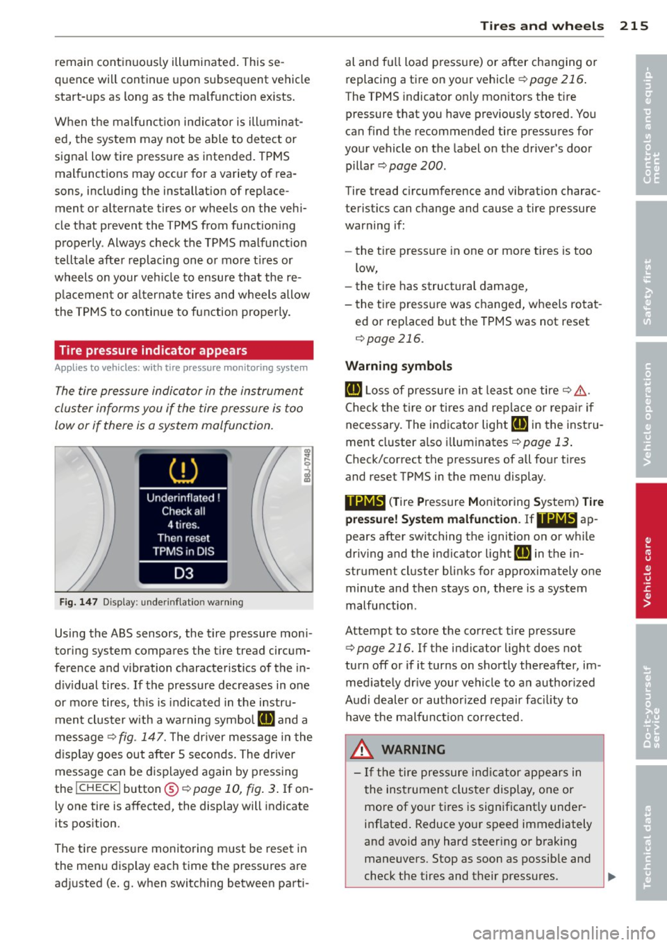
The tire pressure indicator in the instrument
cluster informs you if the tire pressure is too
low or if there is a system malfunction.
F ig. 1 47 Disp lay : under infla tion warn ing
Using the ABS sensors, the tire pressure moni
toring system compares the t ire tread circum
fe rence and vibration characteristics of the in
d iv idual tires . If the pressure decreases in one
or mo re tires, th is is indicated in the instru
ment clus ter with a warning symbol
RE and a
message
'* fig. 147. The dr iver message in the
d isp lay goes out after 5 seconds. The driver
message can be d isplayed again by pressing
the
! CHECK I button @¢ page 10, fig . 3 . If on
ly one tire is affected, the display will indicate
its pos ition.
The ti re pressure monito ring m ust be reset in
the menu display each time the pressures are
ad justed (e.g. when switching between parti-
Tire s an d wheel s 215
al and fu ll load pressure) or after changing o r
replacing a tire on your vehicle '*
page 216.
The TPMS indicator on ly mon itors the t ire
pressure that you have previously stored . You
can f ind the recommended tire pressures for
your vehicle on the label on the driver's door
pillar ¢
page 200.
Tire tread circumference and vibration charac
teristics can change and cause a tire pressure
warning if:
- the t ire press ure in one or more tires is too
low,
- the tire has structural damage,
- the t ire press ure was changed, wheels rotat -
ed or rep laced but the TPMS was not reset
¢ page 216.
Warning symbo ls
RE L oss of pressure in a t least one tire ¢ ,&..
Check the tire or tires and rep lace or repa ir if
necessary . The indicator light
RE in the inst ru
ment cluster a lso i lluminates
¢ page 13 .
Check/correct the press ures of all four tires
and reset TPMS in the menu display .
Iii;~, (T ire Pressure Monitoring System) Ti re
pre ssure! System malfun ction .
Ifllilff' ap
pears after switching the ignition on or whi le
driv ing and the indicator light
RE in the in
strument cluster blinks for approx imately one
minute and then stays on, there is a system
malfunction .
Attempt to store the correct tire pressure '*
page 216. If the indicator light does not
turn off or if it turns on shortly thereafter, im
med iate ly dr ive your vehicle to a n author ized
Audi dealer or author ized repair fac ility to
have the malfunct io n cor rected.
.8, WARNING
-
- If the tire pressure ind ic a tor ap pears in
the ins trumen t cluster display, one or
more of your tires is significant ly under
inflated . Reduce yo ur speed immediately
and avoid any hard steer ing or braking
maneuvers. Stop as soon as possible and
check the tires and their pressures.
~
•
•
Page 231 of 262
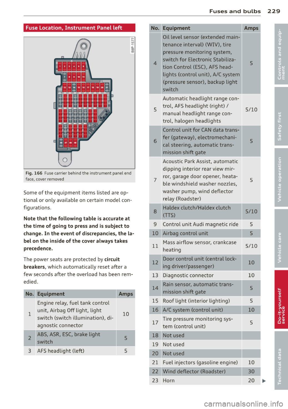
Fuse Location, Instrument Panel left
0
Fig. 166 Fu se ca rrier behin d th e in strum en t pane l end
fa ce, cover re move d
Some of the equipmen t items lis ted a re op
tional or only available on certain model con
f igurations.
N ote th at the foll ow ing table is ac curate at
the t ime of go in g to press and is subje ct to
c hang e. In t he event of d iscr epan cies, the la
b el on the in side of th e cove r alw ay s take s
precedence .
The power sea ts are pro te ct ed by circu it
break ers,
which automatically reset after a
few seconds after the overload has been rem
ed ied .
No. Equipment
1
2
3
Engine relay, fuel tank contro l
unit, A irbag Off light , light
switch (sw itch illumi nation), di -
agnosti c connector
ABS, ASR, ESC, brake light switch
AFS headlight (le ft)
Amps
10
5
5
Fu se s and bulb s 229
No.
4
5
Equipment
Oil level sensor (extended main-
tenance interval) (WIV), tire
pressure monitoring system,
switch for Electronic Stabiliza-
tion Control (ESC), AFS head-lights (control unit), A/C system
(pressure sensor), backup light
switch
Automatic headlight range con trol, AFS headlight (right) /
manual headlight range con
trol, halogen headlights
Control unit for CAN data trans-
6 fer (gateway), electromechani cal steering, automatic trans
mission shift gate
7 Acoust
ic Park Assist, automatic
dipping interior rear view mir-
ror, garage door opener, heata
ble windshield washer nozzles,
washer pump, w ind deflector
re lay (Roadster)
--r-HaldeX clutch/Haldex clutch
(TTS)
8
Amps
5
5/10
5
5
5/10
9 Control un it Audi magnetic ride 5
----10 Airbag control unit 5
Mass airflow sensor, crankcase
11 heat ing
Door control unit (central lock-
12 ing driver/passenger)
13 Diagnostic conne ctor
Rain sensor, automatic trans-
14 mission shift gate
15 Roof light (inter ior lighting)
16 A/C system (control unit)
17 Tire pressure monitoring sys
tem (control un it)
--~-18 Not used
19 Not used 5/10
10
10
5
5
10
5
I
I
I
20 -------21 Fuel injectors (gasoline engine) 10
22 Wind deflecto r (Roadster) 30
23 Horn 20
IIJ>,
Page 232 of 262
230 Fuses and bulbs
-No. Equipment
24 Transmission (control unit)
25 Heater rear
window Coupe/
heated rear window Roadster
26 Driver's side power window
27 Passenger's side power window
28 Not used
29 Washer pump
30 Cigarette lighter
31 Starter
32 Steering column module
33 Instrument cluster
34 Radio navigation system, radio
35 Audio amplifier
36 Engine (control unit)
37 CAN (Gateway)
38 Cigarette lighter
39 Not used
40
------------4 l Not used
42
43 Not used
44
45 Not used
46
47 SOARS tuner, cell phone pack-
age, TV tuner
48
49 Not used
Fuse location, left side of engine
compartment Amps
15
30/20
30
30
-15
20
40 5
5
20/15
30
10 5
20
-
-
5
5
Fig. 167 Illust ration of fuse holder on left side of en·
gine compartment: fuses (without fuse cover)
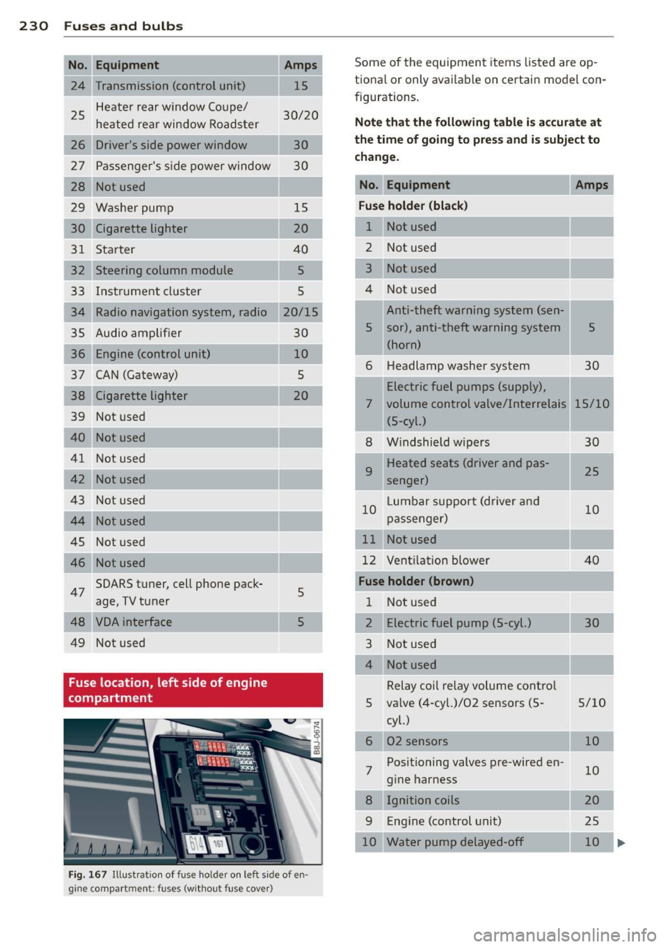
Some of the equipment items listed are op-
t ional or only available on certain model con-
figurations.
Note that the following table is accurate at
the time of going to press and is subject to
change.
No. Equipment Amps
Fuse holder (black)
1 Not used
-2 Not used
3 Not used
4 Not used
Anti-theft warning system (sen-
'
5 sor), anti-theft warning system 5
(horn)
6 Headlamp
washer system
30
Electric fuel pumps (supply),
7 volume control valve/Interrelais 15/10 (5-cyl.)
8 Windshield wipers
30
9 Heated seats (driver and pas-
25
senger)
10 Lumbar
support (driver and
10
passenger)
11 Not used
12 Ventilation blower 40
Fuse holder (brown)
1 Not used
2 Electric fuel pump (5-cyl.) 30
3 Not used
Relay coil relay volume control
5 valve (4-cyl.)/02 sensors (5- 5/10
7 cyl.)
02 sensors
Positioning valves pre-wired en
gine harness
Ignition coils
9 Engine (control unit)
10 Water pump delayed-off 10
10
20
25 10 ..,_.
Page 252 of 262
250 Index
Distance . . . . . . . . . . . . . . . . . . . . . . . . . . . 23
Driver information system Boost .......................... .. 28
E ng ine oi l tempe ratu re d isplay .. .. .... 26
Engine oil temperatu re indicator ...... 28
Menu button . . . . . . . . . . . . . . . . . . . . . . 25
Menu display . . . . . . . . . . . . . . . . . . . . . . 24
Open door or front lid warning . . . . . . . . 22
Outside temperature display .. .. .. .. . . 22
Red symbols ................. ...... 13
Service interval display ...... .. .. .. .. 28
Setting .. .. ... .... ...... ... ... .. .. 26
Sound system display . . . . . . . . . . . . . . . 22
Trip computer. . . . . . . . . . . . . . . . . . . . . . 23
ye llow symbo ls ......... .. .. .. .. .. .. 13
Driver seat
refer to Seat ing pos ition . ........ .. .. 91
Driving Run-flat tires . ........... .... .... . 218
Driving safely . . . . . . . . . . . . . . . . . . . . . . . 90
Driving through water ........ .. .. ... 160
Duplicate key .............. ... .... .. 32
Dust filter . ... .............. .. .. .. .. 67
E
Efficiency program . . . . . . . . . . . . . . . . . . . 26
Fuel economy messages ..... .. .. .... 27
Memory levels . . . . . . . . . . . . . . . . . . . . . 23
Other equipment ........... .. .. .. .. 27
Elapsed time . . . . . . . . . . . . . . . . . . . . . . . . 23
Electro-mechanical power assist . . . 17, 155
E lectronic diffe rent ial lock (EDL) .. .. ... 150
Warn ing/ indicator lights ....... .. .... 18
Electronic immobilizer . . . . . . . . . . . . 12, 33
Electronic power control EPC warning/indicator light . ..... .. .. 19
E lect ronic speed limiter . . . . . . . . . . . . . . . 31
Electronic Stability Control (ESC) Warning/indicator lights ..... .. .. .. . . 17
Electronic Stabilization Control (ESC) . .. 150
E mergency flasher . . . . . . . . . . . . . . . . . . . 45
Warn ing/ indicator l ights ... .... .... .. 21
Emergency locking ............. .... .. 37
Emergency operation
Rear lid . . . . . . . . . . . . . . . . . . . . . . . . . . . 38
E mergency starting ........ .... ..... 232 Emergency towing
.............. .... 234
Energy management . ............ ... 156
Battery power ................ .... 157
Driver notification ............. .. .. 157
Engine Checking and filling locations .... .. .. 182
Coolant . .. ... ... .. .......... ... .. 187
Hood . .... .. .. .. ............. .. .. 180
Starting . . . . . . . . . . . . . . . . . . . . . . 71, 72
Starting with jumper cables ... .. .. .. 232
Stopping .. .... .. .. .............. .. 73
Engine compartment ......... ... .. .. 182
Safety instructions ... .......... .. .. 180
Working in the eng ine compartment 180
Engine coolant system Malfunction ..... ... ........... ... . 16
Radiator fan . .. .. ..... ..... ... .. .. 189
Temperature gauge ....... ..... .. .. . 11
Engine cooling system ........... .... 187
Adding coolant ................ .... 188
Checking the engine coolant level ..... 187
Engine data ..... .. ................ . 240
Engine hood
Closing . .. .. .. .. ............... .. 180
How to release the hood .......... .. 180
Engine oil ...... .. .. ..... ... ... .. .. 182
Adding . ...... .. .. ..... ... ... .. .. 185
Additives .. .. .. .. .. ... ........ .... 185
Changi ng ... .. .. ............. .. .. 186
Checking the engine oil leve l ..... .... 185
Indications and conditions requiring ex-
tra checking ..... ................ . 185
Oil consumption . ................. . 184
Oil grades . ................... .... 182
Recommended oil check intervals . .. .. 185
Specification and viscosity . ...... .. .. 182
Temperature display ........ ... .. .. . 26
Engine oil level .... ................ .. 19
Engine oil pressu re (ma lfunction) .... .. . 16
Engine oil sensor defective . . . . . . . . . . . . 19
Engine oil temperature indicator ........ 28
Engine speed limitation . ......... .. .. . 19
Environment Break-in period .................... 159
Catalytic converter ....... ...... .. .. 160
Dispos ing of your veh icle battery . . . . . 191
Driving at high speeds . ...... ... .. .. 161
Page 255 of 262
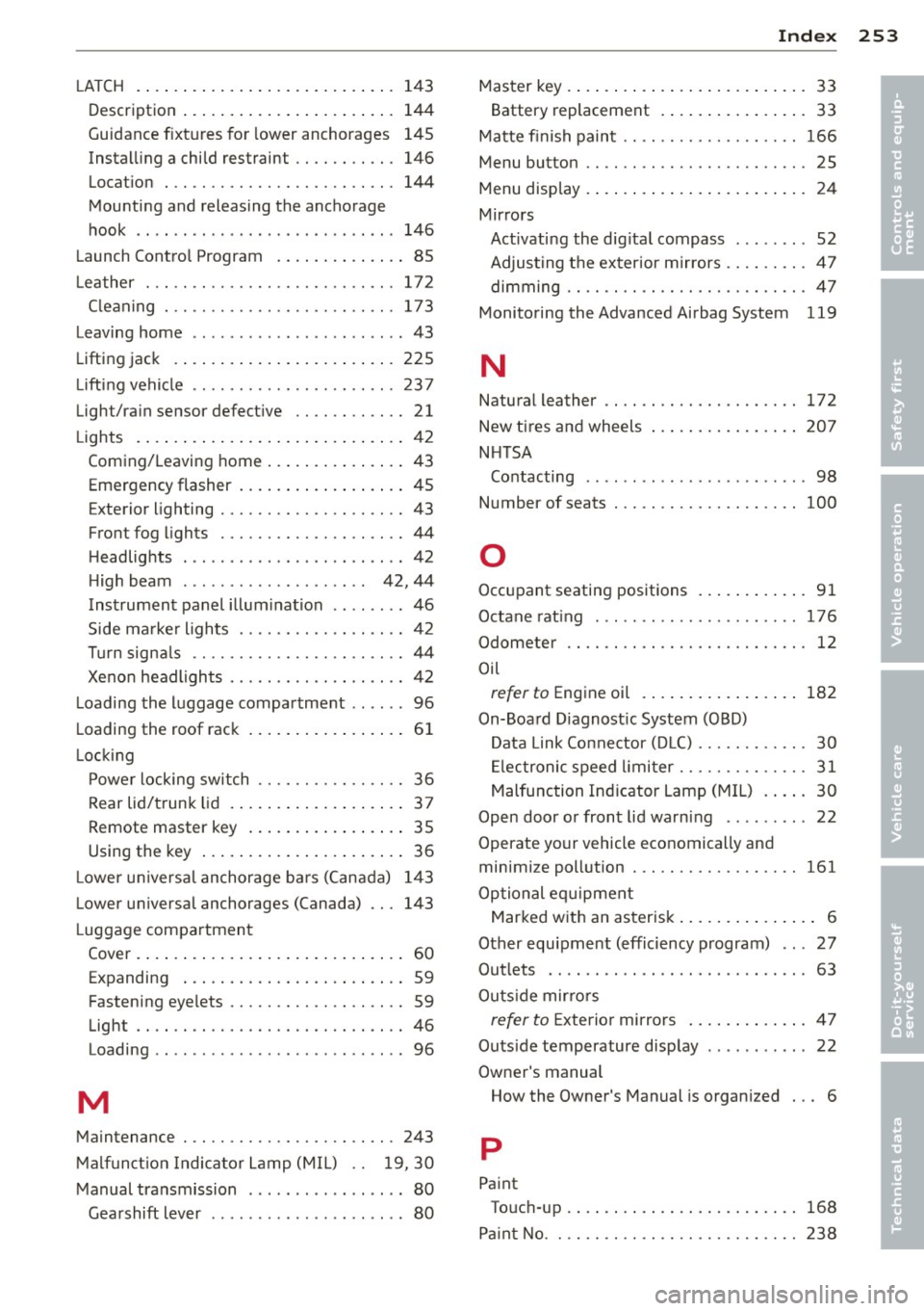
-----------------------------~I~ n~ d~ e~x 253
LA T CH . ..... .. ............ .... .... 143
Description ................. ... ... 144
Guidance f ixtures for lower anchorages 145
Installing a child restraint .. .... .. ... 146
Location
144
Mounting and releasing the anchorage
hook .. .. .. .. ........ ... .. ... ... . 146
Launch Control Program . . . . . . . . . . . . . . 85
L eather . . . . . . . . . . . . . . . . . . . . . . . . . . . 172
C leaning . .. ............. .. .. .. .. . 173
Leaving home ................ .... ... 43
Lifting jack .. ................ ... ... 225
Lifting vehicle ............. .. .. .. .. . 237
Light/rain sensor defective .. .. .. .. .. .. 21
Lights . ..... .. ................ ..... 42
Coming/Leaving home ........... .. .. 43
Emergency flasher .................. 45
Exterior lighting .......... .... .. .. .. 43
Front fog lights .......... .. .. .. .. .. 44
Headlights ............... ... ... ... 42
High beam . . . . . . . . . . . . . . . . . . . . 42, 44
Instrument panel illumination .. . ... .. 46
Side marker lights ........ .. .. .. .. .. 42
Turn signals .. ........... .. .. .. .... 44
Xenon headlights ......... .. .. .. .. .. 42
Loading the luggage compartment ...... 96
Loading the roof rack .......... ... .. .. 61
L ocking
Power locking switch ........ .. .. .. .. 36
Rear lid/trunk lid . . . . . . . . . . . . . . . . . . . 3 7
Remote master key .......... ... .. .. 35
Using the key .................. .... 36
L ower universal anchorage ba rs (Canada) 143
Lower universal anchorages (Canada) 143
L uggage compartment
Cover . ... .. .. ................ ..... 60
Expanding . . . . . . . . . . . . . . . . . . . . . . . . 59
Fastening eyelets ......... .. .. .. .. .. 59
Light .. ... . .... ............. .. .. .. 46
Loading . ... ... .. .. ...... .. .. .. .. .. 96
M
Maintenance . ............. .... .. ... 243
Malfunction Indicator Lamp (MIL) . . 19, 30
Manual transmission ............ .... . 80
Gearshift lever ... .. ...... .. .. .. .. .. 80 Master key ...
..... .................. 33
Battery replacement . . . . . . . . . . . . . . . . 33
Matte finish paint .. ................. 166
Menu button .. .. .. ................. . 25
Menu display . . . . . . . . . . . . . . . . . . . . . . . . 24
Mirrors Activating the dig ita l compass ...... .. 52
Adjusting the exterior mirrors .... .. .. . 47
dimming .. .. .. .. ... .. .......... .. . 47
Monitoring the Advanced Airbag System 119
N
Natural leather .. .. ................. 172
New tires and wheels
NHTSA 207
Contacting ...... .. ................ 98
Number of seats . .. .... ............. 100
0
Occupant seating positions .......... .. 91
Octane rating ... .. .... ........... . .
Odometer
.. .. .. .. ..................
Oil 176
12
refer to Engine oil ................ . 182
On-Board Diagnostic System (OBD)
Data Link Connector (DLC) ....... .. .. . 30
Electronic speed limiter ......... .. .. . 31
Malfunction Indicator Lamp (MIL) ... .. 30
Open door or front lid warn ing ....... .. 22
Operate your vehicle economically and
minimize pollution . ................. 161
Optional eq uipment
Marked with an asterisk . . . . . . . . . . . . . . . 6
Other equipment (efficiency program) .. . 27
Outlets ...... .. ...... ............. . 63
Outs ide mirrors
refer to Exterior mirrors ............. 47
Outs ide temperature display . . . . . . . . . . . 22
Owner's manual How the Owner's Manual is organized . .. 6
p
Paint
Touch-up ... ... .... ............... 168
Pa int No . 238
•
•
Page 256 of 262

254 Index
Park assist . . . . . . . . . . . . . . . . . . . . . . . . . . 78
Park ing ... .. ................ ... 74,82
Parking brake ....................... 73
Park ing brake warn ing ................ 15
Park ing on a decline (downhill) ... .. .... 74
Parking on an incline (uphill) ... ... ... .. 74
Parts rep lacement .................. 245
PASSENGER AIR BAG OFF light . .. ..... 119
Passive safety system . . . . . . . . . . . . . . . . . 90
Pedals .. .... .................. ... .. 95
Phys ica l pr inciples of a frontal coll is ion . 101
Polishing .. .. ............. .. .. .. .. . 167
Pollen filter . . . . . . . . . . . . . . . . . . . . . . . . . 67
Poll utant fi lter .. .. ..... ... .. .. .... .. 67
Powe r locking switch ............ ..... 36
Power locking system . . . . . . . . . . . . . . . . . 34
Conven ience close/open feature ..... .. 40
Lock ing and unlocking the vehicle from
in side ... .. ... .... ...... ... ... .. .. 36
Opening and clos ing the w indows ...... 40
Rear lid/t runk l id ................... 37
Remote cont rol .......... .. .. .... . . 33
Un lock ing and locking veh icle ... .. .. . . 35
Powe r outlets
63
Powe r seats
Ad justment ............. .. .. .. .. .. 56
P ower steering
refer to Electro -mechanica l power as -
sist . . . . . . . . . . . . . . . . . . . . . . . . . 17, 155
Powe r window switches . . . . . . . . . . . . . . . 39
Reactiva ting t he system . .. .. .. .... .. 4 1
Pregnant women Specia l cons iderations when wearing a
safety belt .... .... ...... .. .. .. .. . 105
Programming the Homelink ® universal re
mote contro l . . . . . . . . . . . . . . . . . . . . . . . . 87
Pr ope r occupant sea ting pos it ions .. .... 9 1
Proper safety belt pos it ion ........ .... 105
Prope r seat ing posit ion
Front passenger . . . . . . . . . . . . . . . . . . . . 92
Occupants ......................... 91
Rear passengers . . . . . . . . . . . . . . . . . . . . 93
Q
Qua rtz clock . . . . . . . . . . . . . . . . . . . . . . . . 11 quatt
ro ®
refer to All-whee l drive
Question What happens to unbelted o ccupants?
Why sa fe ty belts? ............. ... .
R
15S
102
100
Radiator fan ...... ............. .... 189
Rain sensor defective . . . . . . . . . . . . . . . . . 21
Reading ligh ts ... .. .. ... ..... ... .. .. . 45
Rea r lid ....... .... .... ........... .. 37
Emergency re lease . . . . . . . . . . . . . . . . . . 38
Rear light defect ive . . . . . . . . . . . . . . . . . . 20
Rea r spo ile r . .. .. .. ... .. ..... ... .. .. 153
Rear v iew m irror ........ ........... .. 47
Rear window defogger . . . . . . . . . . . . . . . . 70
Rea r window s helf . . . . . . . . . . . . . . . . . . . 58
Refuell ing .. .... .. ............. .... 178
Re lease lever for hood . .. ..... ... .. .. 180
Remote contro l . . . . . . . . . . . . . . . . . . 33, 36
Remote contro l garage door opener
(Homelink ®) .. .. .. ............. .. .. . 87
Remote maste r key
U nlocking and locking ... .... ... .. .. . 35
Remote rea r lid re lease . ...... ...... .. 37
Repair ma nuals ..................... 243
Repa irs
Airbag system ... .. ... ..... ... .. .. 122
Rep lacement parts ........... ....... 245
Rep lacing
Wheel rims .... .. ............. .... 207
Rep lacing a fuse ... .. .... .... ... .. .. 228
Replacing light bulbs ........... ... .. 231
Rep lacing tires and wheels ........ .... 208
Rep lac ing windsh ield w iper b la d es . .. .. . 51
Repo rting Sa fety Defects .............. 98
Reset button . . . . . . . . . . . . . . . . . . . . . . . . 12
Resetting remote contro l . . . . . . . . . . . . . . 36
Retractor . . . . . . . . . . . . . . . . . . . . . . . . . . 104
Reverse (Automat ic transm iss ion) .. .... . 81
Rims Cast alloy ..... ....... ........... . 169
Replac ing . .... .. ............. .... 20 7
Stee l rim s ... .. .. ............. .... 169