AUDI TT 2021 Owner´s Manual
Manufacturer: AUDI, Model Year: 2021, Model line: TT, Model: AUDI TT 2021Pages: 280, PDF Size: 99.18 MB
Page 251 of 280

8S1012721BE
Emergency assistance
battery that is giving power must not be less
than the capacity of the drained vehicle battery.
Jump start cable
Only use a jump start cable with a large enough
diameter. Note the manufacturer's specifica-
tions.
Only use a jump start cable with insulated termi-
nal clamps.
Positive cable - usually red.
Negative cable - usually black.
ZA WARNING
— A drained battery can freeze at tempera-
tures around 32 °F (0 °C). If the vehicle bat-
tery is frozen, it must be thawed before con-
necting the jump start cables. If it is not, the
risk of an explosion and chemical burns in-
creases. After jump starting the vehicle,
drive to an authorized Audi dealer or author-
ized Audi Service Facility immediately to
have the vehicle battery checked.
— Read the warnings when working in the en-
gine compartment > page 200.
— Handling the jump start cables incorrectly
may cause the vehicle battery to explode
and lead to serious injuries.
@) Note
Jump start cables can cause considerable
damage to the vehicle electrical system if
they are connected incorrectly.
G) Tips
— There must be no contact between the
vehicles, or else voltage could flow when
connecting the positive terminal and drain
the vehicle battery of the vehicle providing
the jump start.
— The drained vehicle battery must be con-
nected correctly to the electrical system.
— Switch off electrical equipment that is not
needed.
arte la alate)
Both jump start cables must be connected in the
correct order.
Fig. 192 Engine compartment: connectors for jump start
cables or a charger
Fig. 193 Connecting the jump start cables
The jump start cable connections are located in
the engine compartment.
Follow the information about the vehicle battery
=> page 210.
Connecting the positive cable (red) to the
positive terminal
> Open the red cover on the positive terminal
> fig. 192.
1. Attach one end of the positive cable (red) to
the jump start connection @ > fig. 193 on
your vehicle.
2. Attach the other end of the positive cable
(red) to the positive terminal @) on the pow-
er source.
Connecting the negative cable (black) to the
negative terminal
3. Attach one end of the negative cable (black)
to the negative terminal @) on the power
source. >
249
Page 252 of 280
Emergency assistance
4. Attach the other end of the negative cable
(black) to the jump start connection @ on
the vehicle.
Starting the engine
> Start the engine in the vehicle giving the charge
and let it run at idle.
> Now start the engine in your vehicle, which has
the
drained battery.
> If the engine does not start, stop the starting
procedure after 10 seconds and then repeat it
after approximately 30 seconds.
> Turn on the rear window defogger in your vehi-
cle in order to reduce any voltage peaks that
may occur when disconnecting the jump start
cables. The headlights must be switched off.
> With the engines running, remove the cables in
reverse order of the way they were installed.
> Close the red cover on the positive terminal.
ZA\ WARNING
— Never connect the jump start cable directly
to your vehicle battery. Only use the connec-
tions in the engine compartment.
— Do not touch the non-insulated parts of the
terminal clamps. The cable must also not
come into contact with vehicle components
that conduct electricity when it is connected
to the positive vehicle battery terminal. This
can cause a short circuit.
— The locking bolts on the battery cells must
be tightened securely.
— Keep ignition sources (open flames, burning
cigarettes, etc.) away from the vehicle bat-
teries to reduce the risk of an explosion.
— Route the jump start cables so they cannot
get caught in the moving parts in the other
vehicle's engine compartment.
C) Note
Please note that the connecting process previ-
ously described for the jump start cables is in-
tended for when your vehicle is being jump
started.
250
G) Tips
Make sure that the connected jump start ca-
bles have sufficient contact with metal.
Towing
General information
You should only perform the steps that follow if
you have the necessary tools and technical ex-
pertise.
Towing requires a certain amount of practice.
Audi recommends contacting a towing company
to have the vehicle transported.
You should only have your vehicle towed by an-
other vehicle when disabled in exceptional cir-
cumstances. Inexperienced drivers should not
tow.
Notes on towing
When the engine is stopped, the transmission
will not be sufficiently lubricated if traveling at
high speeds and long distances:
— The maximum permitted towing speed is 30
mph (50 km/h).
— The maximum permitted towing distance is 30
miles (SO km).
Additional information on towing with a tow
truck
The vehicle may only be towed with the front axle
raised. Do not wrap any chains or cables around
the brake lines.
If the vehicle should be towed with the axle
raised, then the ignition must be switched off to
reduce the risk of damage to the drivetrain.
Tow bar and towing cable
The vehicle can be towed with a tow bar or tow-
ing cable. Both drivers should be familiar with
the special considerations when towing, especial-
ly when using a towing cable.
Always make sure the traction force does not ex-
ceed the permitted level and there are no shock
loading conditions. There is always the risk of the >
Page 253 of 280
8S1012721BE
Emergency assistance
coupling becoming overloaded when driving off-
road.
For the most safety and security, drive with a tow
bar. You should use a towing cable only if a tow
bar is not available. Use a towing cable made of
synthetic elastic cable similar elastic material.
ZA\ WARNING
— Towing highly increases the risk of an acci-
dent, for example from colliding with the
towing vehicle.
— To reduce the risk of an accident, do not al-
low anyone to remain inside the vehicle
when it is being transported by a tow truck
or a special transporter.
® Note
— If normal towing is not possible, for exam-
ple if the transmission is faulty or if the
towing distance is greater than 30 miles
(50 km), then transport the vehicle ona
special carrier.
— If the vehicle is towed by a tow truck at the
axle that is not permitted, this can cause se-
vere damage to the transmission.
— The vehicle must not be tow started for
technical reasons.
G) Tips
— If there is a power failure, the selector lever
will not move out of the "P" position. The
parking lock must be released using the
emergency release before towing the vehi-
cle > page 88.
— Follow the local legal regulations for tow-
ing.
Read and follow the important information un-
der > page 250.
Preparations
> Only secure the towing cable or tow bar at the
designated towing loops > page 2517,
=> page 252.
> Make sure the towing cable is not twisted. Oth-
erwise it could disconnect from the towing loop
while towing.
> Switch the emergency flashers on in both
vehicles > page 38. However, do not do this if it
prohibited by law.
Towing vehicle (front)
> Only start to drive when the towing cable is
taut.
> Be especially careful when accelerating.
» Avoid sudden braking or driving maneuvers.
Vehicle being towed (rear)
> Make sure the ignition is switched on so that
the steering wheel is not locked and so that you
can use the turn signals, the horn, and the
windshield wipers if needed > /A\.
> Switching it off before the vehicle has stopped
may impair the function of the brake booster
and power steering. You would then need to
use more force to steer and brake the vehicle.
> Release the parking brake > page 79.
> Select the “N” selector lever position.
> Make sure the towing cable is always taut.
ZA\ WARNING
— Never tow a vehicle using a tow bar or tow-
ing cable if the vehicle does not have electri-
cal power.
— If the vehicle runs out of power while it is
being towed, stop towing the vehicle imme-
diately and consult an authorized Audi deal-
er or qualified repair facility.
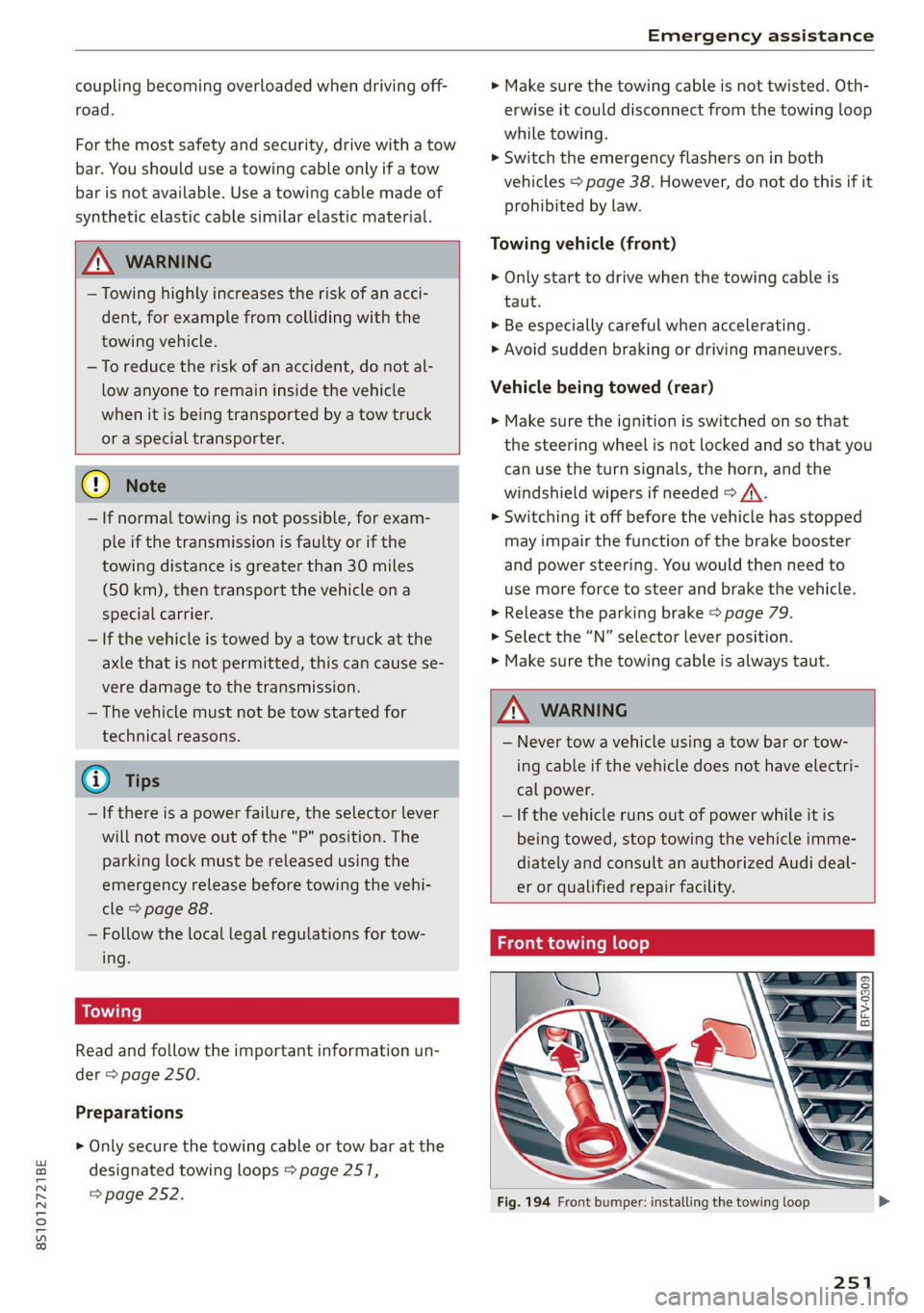
Front towing loop
Fig. 194 Front bumper: installing the towing loop
251
Page 254 of 280
Emergency assistance
The threaded opening for the towing loop is lo-
cated on the right side of the front bumper.
> Remove the towing loop from the vehicle tool
kit > page 242.
> Press the cap inward with brief, strong pressure
> fig. 194. The cap will loosen from the bump-
er.
> Tighten the towing eye as far as it will go into
the mount. Use a suitable object to tighten the
towing eye completely and securely in the
mount.
>» After using, place the towing loop back in the
vehicle tool kit.
A WARNING
If the towing loop is not tightened until it
stops when installing, the threads may be
pulled out when towing the vehicle and result
in an accident.
@ Tips
Depending on the model, the shape of the cap
can vary.
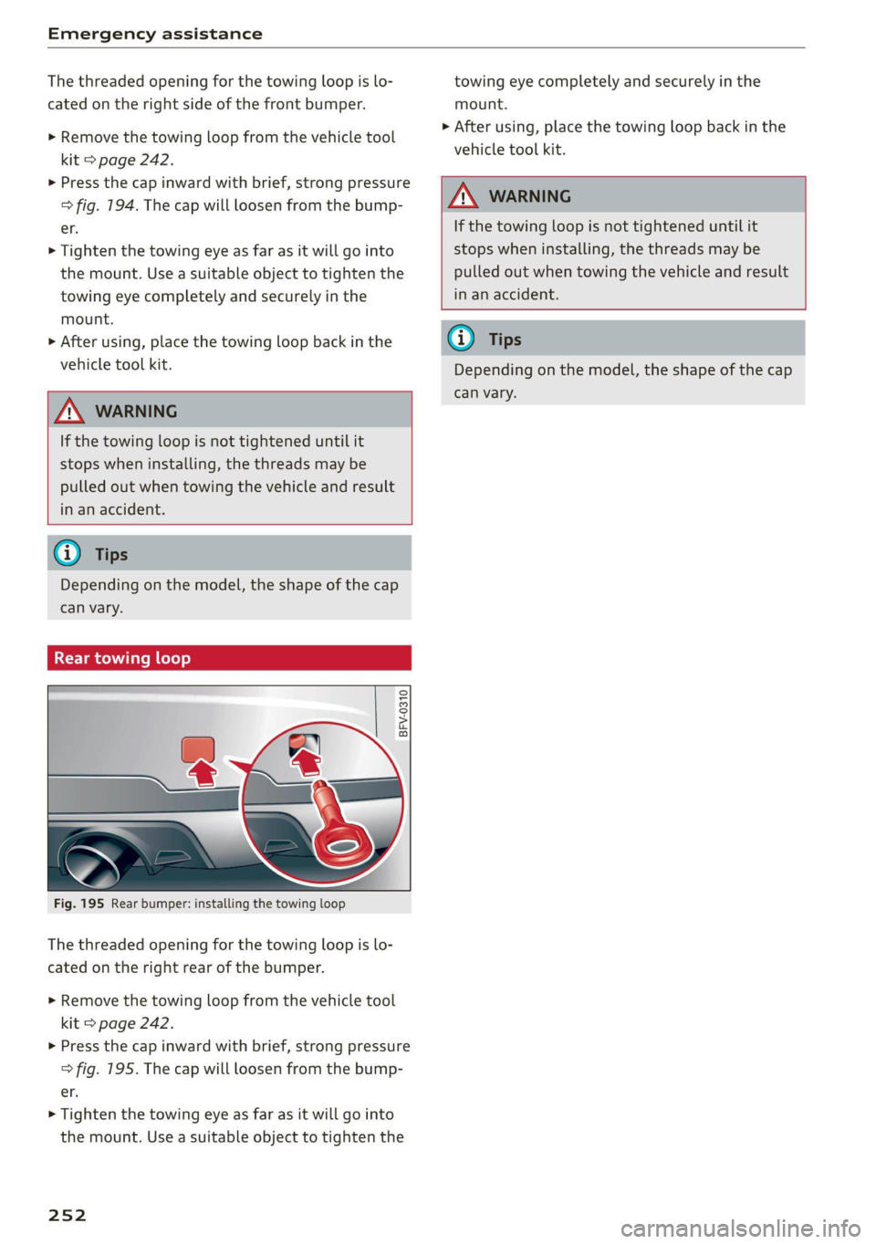
Rear towing loop
BFV-0310
Fig. 195 Rear bumper: installing the towing loop
The threaded opening for the towing loop is lo-
cated on the right rear of the bumper.
> Remove the towing loop from the vehicle tool
kit > page 242.
> Press the cap inward with brief, strong pressure
> fig. 195. The cap will loosen from the bump-
er.
> Tighten the towing eye as far as it will go into
the mount. Use a suitable object to tighten the
252
towing eye completely and securely in the
mount.
> After using, place the towing loop back in the
vehicle tool kit.
Z\ WARNING
If the towing loop is not tightened until it
stops when installing, the threads may be
pulled out when towing the vehicle and result
in an accident.
G) Tips
Depending on the model, the shape of the cap
can vary.
Page 255 of 280

8S1012721BE
Fuses and bulbs
Fuses and bulbs
Fuses
eer mee
S 6
= o
q
= 2 % a.
Fig. 197 Left side of the engine compartment: fuse cover
A fuse that has blown will have metal strips that
have burned through. The fuses are located in the
interior and in the engine compartment.
Fuses in the interior
> Switch the ignition and all electrical equipment
off.
> Check the table that follows to see which fuse
belongs to the equipment.
» Remove the cover > fig. 196.
> Remove the plastic clip from the fuse panel
cover in the engine compartment © fig. 197.
> Remove the fuse using the clip.
> Replace the blown fuse only with a fuse that
has the same amp rating.
> Install the cover.
Fuses in the engine compartment
> Switch the ignition and all electrical equipment
off > A\.
> Check the following table to see which fuse be-
longs to the equipment > page 255.
> Remove the fuse panel cover > fig. 197.
> Remove the plastic clip from the fuse panel
cover > fig. 197.
> Remove the fuse using the clip.
> Replace the blown fuse only with a fuse that
has the same amp rating.
Fuse color identification
Color Current rating
in amps
Black 1
Purple 3
Light brown 5
Brown 7.5
Red 10
Blue 15
Yellow 20
White or transparent [25
Green 30
Orange 40
Z\ WARNING
Do not repair fuses and never replace a blown
fuse with one that has a higher amp rating.
This can cause damage to the electrical sys-
tem and increases the risk of fire.
CG) Note
If a new fuse burns out again shortly after you
have installed it, have the electrical system
checked as soon as possible by an authorized
Audi dealer or authorized Audi Service Facility.
(i) Tips
— The following table does not list fuse loca-
tions that are not used.
— Some of the equipment listed in the follow-
ing tables applies only to certain model ver-
sions or certain optional equipment.
253
Page 256 of 280
Fuses and bulbs
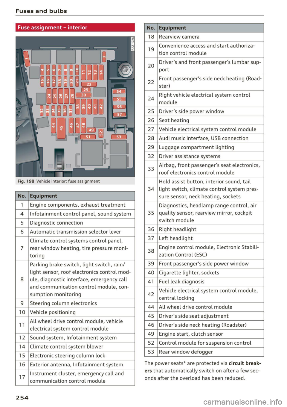
Fuse assign
No. Equipment
18 Rearview camera
19
Convenience access and start authoriza-
tion control module
20
Driver’s and front passenger’s lumbar sup-
port
Fig. 198 Vehicle interior: fuse assignment
22
Front passenger's side neck heating (Road-
ster)
24
Right vehicle electrical system control
module
25 Driver’s side power window
26 Seat heating
27 Vehicle electrical system control module
28 Audi music interface, USB connection
29 Luggage compartment lighting
32 Driver assistance systems
33
Airbag, front passenger’s seat electronics,
roof electronics control module
Hold assist button, interior sound, tail
34 | light switch, climate control system pres-
No. | Equipment sure sensor, neck heating, sockets
1 | Engine components, exhaust treatment Diagnostics, headlamp range control, air
4
|Infotainment control panel, sound system 35 | quality sensor, rearview mirror, cockpit
5 | Diagnostic connection switch module
6 |Automatic transmission selector lever 36 | Right headlight
Climate control systems control panel, 37 [Left headlight
7 |rear window heating, tire pressure moni- 38 Engine control module, Electronic Stabili-
toring zation Control (ESC)
Parking brake switch, light switch, rain/ 39 | Front passenger's side power window
light sensor, roof electronics control mod- AO | Cigarette lighter, sockets
8 |ule, diagnostic interface, emergency call 41 | Fuel leak diagnosis
and communication control module, con- 7 -
SUPADRIOR HIORIEOFIA 42 Vehicle electrical system control module,
P 9 central locking
9 |Steeri l lectroni
Sg CeIn ess 44 |All wheel drive control module
10 | Vehicle positionin : ;
P - g - 45 | Driver's side seat adjustment
11 aes oe 46 | Driver's side neck heating (Roadster)
49 | Engine start, clutch sensor
12 |Sound system, Infotainment system g
14 | Cimareconttol system Blower 52 | Control module for suspension control
53 | Rear window defogger
15 | Electronic steering column lock window 99°
16 | Exterior antenna, Infotainment system The power seats* are protected via circuit break-
Instrument cluster, emergency call and ers that automatically switch on after a few sec-
17 | -ommunication control module onds after the overload has been reduced.
254
Page 257 of 280
8S1012721BE
Fuses and bulbs
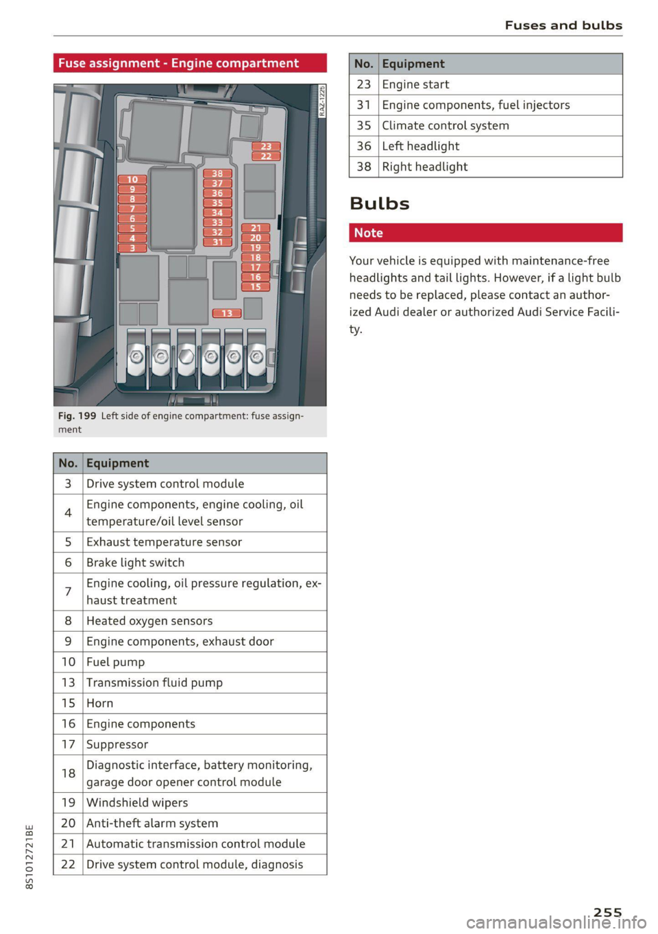
Fig. 199 Left side of engine compartment: fuse assign-
ment.
No.
23 Engine start
341 Engine components, fuel injectors
35 Climate control system
36 Left headlight
3 | Drive system control module
Engine components, engine cooling, oil
temperature/oil level sensor
5 | Exhaust temperature sensor
Brake light switch
haust treatment
Engine cooling, oil pressure regulation, ex-
8 | Heated oxygen sensors
9 |Engine components, exhaust door
10 | Fuel pump
13 |Transmission fluid pump
15 |Horn
16 | Engine components
17 |Suppressor
18
garage door opener control module
Diagnostic interface, battery monitoring,
19 | Windshield wipers
20 | Anti-theft alarm system
21 | Automatic transmission control module
22 | Drive system control module, diagnosis
38
Right headlight
Bulbs
Your vehicle is equipped with maintenance-free
headlights and tail lights. However, if a light bulb
needs to be replaced, please contact an author-
ized Audi dealer or authorized Audi Service Facili-
ty.
255
Page 258 of 280
![AUDI TT 2021 Owner´s Manual Data privacy
Data privacy
Privacy notice
You can find information about responsibility for
data protection in the MMI.
Applies to: MMI: Select: [MENU] button > Audi
connect > right AUDI TT 2021 Owner´s Manual Data privacy
Data privacy
Privacy notice
You can find information about responsibility for
data protection in the MMI.
Applies to: MMI: Select: [MENU] button > Audi
connect > right](/img/6/40287/w960_40287-257.png)
Data privacy
Data privacy
Privacy notice
You can find information about responsibility for
data protection in the MMI.
Applies to: MMI: Select: [MENU] button > Audi
connect > right control button > About Audi con-
nect.
Image recording
Surrounding area monitoring
Applies to: vehicles with surrounding area monitoring
Some vehicle functions require the vehicle’s path
to be detected and evaluated. This is done by
cameras installed permanently on the vehicle
that detect objects in the vehicle's surroundings
(such as obstacles or guard rails). The live images
from the cameras are transmitted to the applica-
ble control module.
The camera images are transmitted to the appli-
cable control module and stored for processing.
The control module analyzes the current camera
image using image evaluation software. This im-
age evaluation software detects anonymized
technical measurements, such as distances to ob-
jects. The control module evaluates these techni-
cal measurements and makes it possible for the
assist systems to control the vehicle, if necessary.
Data memories
~ 1p o
S| =z
x a.
Fig. 200 Driver's side footwell: connection port for the On
Board Diagnostic System (OBD)
Your vehicle is equipped with electronic control
modules for various vehicle systems such as the
256
airbags. These vehicle control modules store data
while driving normally that is required by an au-
thorized Audi dealer or authorized Audi Service
Facility for diagnosis and repair purposes. Only
certain types of data are recorded for a very short
period of time if a control module has detected a
system event. No noises, conversations, or im-
ages will be recorded in the vehicle.
The data may include information such as the ve-
hicle speed, the direction of travel, and informa-
tion about the brake system, or also the behavior
of the restraint system in the event of an acci-
dent. The stored data can be exported and down-
loaded with special devices, which must be con-
nected directly to the vehicle.
On Board Diagnostic System (OBD)
There is a diagnostic connector socket in the driv-
er's side footwell to read out the various control
modules and the event data recorder. Data re-
garding the function and condition of the elec-
tronic control modules is stored in the event
memory. Only have an authorized Audi dealer or
authorized Audi Service Facility read out and de-
lete the event memory.
ZA\ WARNING
— Incorrect use of the connection port for the
On Board Diagnostic System can cause mal-
functions, which can then result in accidents
and serious injuries.
— Only allow an authorized Audi dealer or au-
thorized Audi Service Facility to read out the
motor data.
rash data recorder
Crash data recorder/event data recorder
Your vehicle is not equipped with a crash data re-
corder.
Vehicle information is stored temporarily in a
crash data recorder. This provides detailed in-
sight into the circumstances of an accident. In
vehicles with an airbag system, accident-related
information such as impact speed, seat belt sta-
tus, seat positions and deployment times may be >
Page 259 of 280

8S1012721BE
Data privacy
stored. The scope of information depends on the
particular manufacturer.
The owner must agree to the installation of any
such crash data recorder and it is regulated by
law in some countries.
Transmitted information
Privacy settings
Applies to: vehicles with Audi connect
> Select: [MENU] button > Audi connect > right
control button > Privacy.
Requirement: the ignition must be switched on.
Location, vehicle, and personal data are transmit-
ted when using Audi connect services.
Allowing sending of data
— Select and confirm Activate data connection.
The data module for the use of all Audi connect
services will be active.
Restricting sending of data
— Select and confirm Activate privacy. The data
connection is limited or deactivated depending
on the equipment. The majority of Audi connect
services will not be available.
@) Note
You are responsible for all precautions taken
for data protection, anti-virus protection, and
protection against loss of data on mobile de-
vices that are used to access the Internet
through the Wi-Fi hotspot.
G) Tips
— The following interfaces are not affected by
this setting: Bluetooth, Bluetooth Low Ener-
gy (BLE), Wi-Fi connection, Audi smart-
phone interface (ASI), Near Field Communi-
cation (NFC), charging communication
(high-voltage system), Electronic Toll Col-
lect (ETC), On-Board Diagnostic System
(OBD) if equipped.
— If the transmission of data is limited, data
will still be transmitted to verify subscrip-
tions.
Applies to: vehicles with Audi connect
Audi collects, uses, stores and shares your per-
sonal information, such as contact data, vehicle
data, usage data, driving data and precise geolo-
cation, in order to provide you with the products
and services you have purchased or requested,
and for a number of other purposes, for example,
to track quality issues, to performance and safe-
ty, to meet our internal compliance or legal re-
quirements and to market to customers and po-
tential customers. For a more complete list of
the data we collect, how we use it and with
whom we share it, please visit your Audi nation-
al/sales region website at www.audi.com.
The collection, use and sharing may vary depend-
ing on your model and model year, your subscrip-
tion status, or the service offering. For example,
collection, use and sharing may vary between
Audi connect services, if you have designated a
key user, or if you are driving a model equipped
with persistent data logging. Please review the
complete Privacy Statement to understand our
data handling practices with respect to a particu-
lar service.
You can find additional information about our da-
ta privacy practices in your MMI.
> Select: [MENU] button > Audi connect > right
control button > About Audi connect.
Information about our privacy practices in con-
junction with the mobile Audi connect applica-
tion can be found in the Application’s Privacy
Statement.
For additional information about the privacy
practices relating to Audi connect, myAudi, or
other websites, applications or online services as
well as your obligations with respect to using
these services, and for additional information re-
garding Audi connect terms and conditions,
please visit your Audi national/sales region web-
site at www.audi.com.
257
Page 260 of 280

Accessories and technical changes
Accessories and
technical changes
Warranty
Your vehicle is covered by various warranties:
— New Vehicle Limited Warranty
— Limited Warranty Against Corrosion Perforation
— Emissions Control System Warranties: Federal
Emissions Control System Defect Warranty,
Federal Emissions Performance Warranty
— Applies to: USA models: Kansas Safety Belt
Limited Warranty
— Applies to: USA models: California Emissions
Control Warranties: Short-term Emissions De-
fects Warranty, Long-term Emissions Defects
Warranty, TZEV models Emissions Defects
Warranty, California Emissions Performance
Warranty
You can find detailed information in your Warran-
ty & Maintenance Booklet and in the California
Emissions Booklet*.
Audi Literature Shop
Service information is made available as soon as
possible after a model is introduced and can be
ordered in the Audi Literature Shop: http://
literature.audiusa.com
Driving in other
countries
Government regulations in the United States and
Canada require motor vehicles to comply with
emissions regulations and safety standards.
Therefore, vehicles that were produced for the
U.S. and Canadian markets are different from
vehicles produced for other countries.
If you plan to use your vehicle outside of the Unit-
ed States or Canada, it is possible that:
— Fuel may have a significantly lower octane rat-
ing. Unsuitable fuels can cause engine damage.
— Proper maintenance and repair work may not
be possible because special service equipment,
tools, or measuring devices needed for your ve-
hicle may not be available.
258
— Replacement parts may not always be availa-
ble.
— Navigation systems for vehicles built for the
U.S.A. and Canada will not necessarily work in
Europe, and may not work in other countries.
() Note
Audi is not liable for damage to the vehicle re-
sulting from these country-specific differen-
ces.
Maintenance, repairs,
and technical modifi-
cations
Observe the safety precautions > page 200, Gen-
eral information and > page 246, Raising the ve-
hicle.
General information
Due to the increasing complexity of technology in
these vehicles, as well as the safety and environ-
mental standards that apply, you can only per-
form a very limited amount of repairs and modifi-
cations to the vehicle yourself.
Proof of maintenance work may be required to
submit a claim within the warranty period.
We recommend that you have your vehicle serv-
iced by an authorized Audi dealer or authorized
Audi Service Facility and that Audi Genuine Parts
and Audi Genuine Accessories are used. This
helps to ensure that your vehicle's functionality,
performance, and safety are not impaired.
Maintenance and repairs
Your vehicle was designed to help keep mainte-
nance requirements to a minimum. Some regular
maintenance is required to help ensure that your
vehicle runs in a safe, economical, and reliable
manner. Please refer to your Warranty & Mainte-
nance Booklet for more detailed information
about vehicle maintenance.
When operating the vehicle under more extreme
operating conditions, for example when outside
temperatures are very low or in very dusty envi-
ronments, certain maintenance should be per-
formed between the specified intervals.