jack points AUDI TT 2021 Owner´s Manual
[x] Cancel search | Manufacturer: AUDI, Model Year: 2021, Model line: TT, Model: AUDI TT 2021Pages: 280, PDF Size: 99.18 MB
Page 52 of 280
Sitting correctly and safely
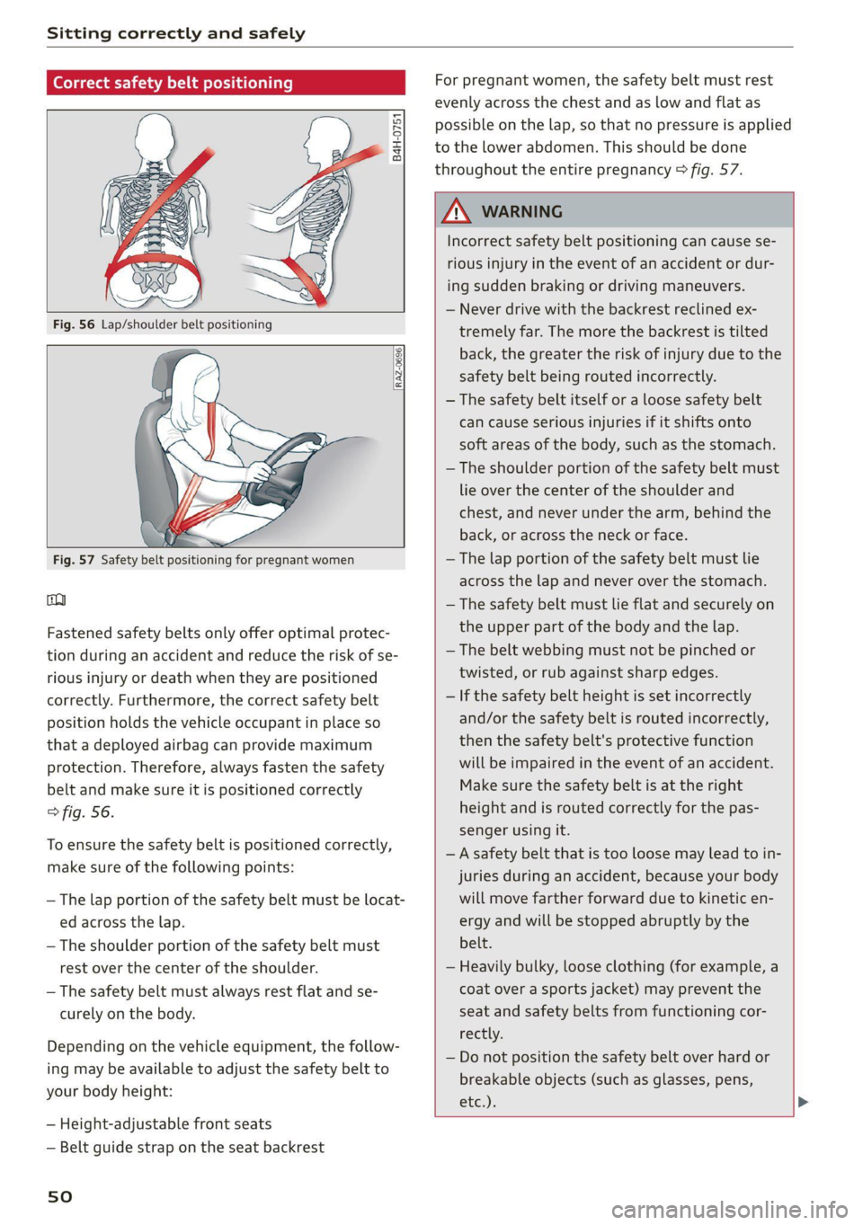
Correct safety belt positioning
B4H-0751
RAZ-0696
Fig. 57 Safety belt positioning for pregnant women
co
Fastened safety belts only offer optimal protec-
tion during an accident and reduce the risk of se-
rious injury or death when they are positioned
correctly. Furthermore, the correct safety belt
position holds the vehicle occupant in place so
that a deployed airbag can provide maximum
protection. Therefore, always fasten the safety
belt and make sure it is positioned correctly
> fig. 56.
To ensure the safety belt is positioned correctly,
make sure of the following points:
—The lap portion of the safety belt must be locat-
ed across the lap.
—The shoulder portion of the safety belt must
rest over the center of the shoulder.
— The safety belt must always rest flat and se-
curely on the body.
Depending on the vehicle equipment, the follow-
ing may be available to adjust the safety belt to
your body height:
— Height-adjustable front seats
— Belt guide strap on the seat backrest
sO
For pregnant women, the safety belt must rest
evenly across the chest and as low and flat as
possible on the lap, so that no pressure is applied
to the lower abdomen. This should be done
throughout the entire pregnancy > fig. 57.
Z\ WARNING
Incorrect safety belt positioning can cause se-
rious injury in the event of an accident or dur-
ing sudden braking or driving maneuvers.
— Never drive with the backrest reclined ex-
tremely far. The more the backrest is tilted
back, the greater the risk of injury due to the
safety belt being routed incorrectly.
— The safety belt itself or a loose safety belt
can cause serious injuries if it shifts onto
soft areas of the body, such as the stomach.
— The shoulder portion of the safety belt must
lie over the center of the shoulder and
chest, and never under the arm, behind the
back, or across the neck or face.
— The lap portion of the safety belt must lie
across the lap and never over the stomach.
— The safety belt must lie flat and securely on
the upper part of the body and the lap.
— The belt webbing must not be pinched or
twisted, or rub against sharp edges.
— If the safety belt height is set incorrectly
and/or the safety belt is routed incorrectly,
then the safety belt's protective function
will be impaired in the event of an accident.
Make sure the safety belt is at the right
height and is routed correctly for the pas-
senger using it.
— A safety belt that is too loose may lead to in-
juries during an accident, because your body
will move farther forward due to kinetic en-
ergy and will be stopped abruptly by the
belt.
— Heavily bulky, loose clothing (for example, a
coat over a sports jacket) may prevent the
seat and safety belts from functioning cor-
rectly.
— Do not position the safety belt over hard or
breakable objects (such as glasses, pens,
etc,),,
Page 248 of 280
Emergency assistance
> Slide the wheel wrench* from the vehicle tool
kit all the way onto the wheel bolt”).
> Turn the wheel bolt approximately one turn to
the left. To achieve the required torque, hold
the end of the wheel wrench*. If the wheel bolt
will not loosen, press carefully on the wheel
wrench* with your foot. Hold onto the vehicle
securely while doing this and make sure your
footing is stable.
Z\ WARNING
To reduce the risk of an accident, only loosen
the wheel bolts gently one turn before raising
the vehicle with the vehicle jack*.
Raising the vehicle
Applies to: vehicles with vehicle jack
A_,
BFv-0094
2 oS a 2
> £
oO
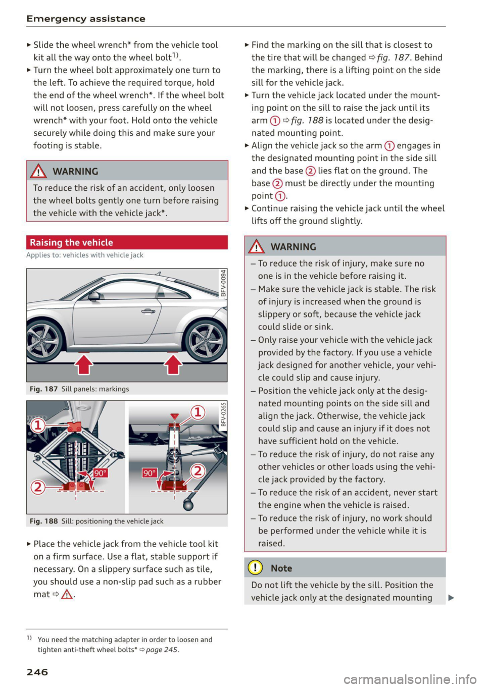
Fig. 188 Sill: positioning the vehicle jack
> Place the vehicle jack from the vehicle tool kit
ona firm surface. Use a flat, stable support if
necessary. On a slippery surface such as tile,
you should use a non-slip pad such as a rubber
mat > /\.
1) You need the matching adapter in order to loosen and
tighten anti-theft wheel bolts* > page 245.
246
> Find the marking on the sill that is closest to
the tire that will be changed © fig. 187. Behind
the marking, there is a lifting point on the side
sill for the vehicle jack.
> Turn the vehicle jack located under the mount-
ing point on the sill to raise the jack until its
arm @) ° fig. 188 is located under the desig-
nated mounting point.
> Align the vehicle jack so the arm (@) engages in
the designated mounting point in the side sill
and the base (2) lies flat on the ground. The
base (2) must be directly under the mounting
point (a).
> Continue raising the vehicle jack until the wheel
lifts off the ground slightly.
Z\ WARNING
—To reduce the risk of injury, make sure no
one is in the vehicle before raising it.
— Make sure the vehicle jack is stable. The risk
of injury is increased when the ground is
slippery or soft, because the vehicle jack
could slide or sink.
— Only raise your vehicle with the vehicle jack
provided by the factory. If you use a vehicle
jack designed for another vehicle, your vehi-
cle could slip and cause injury.
— Position the vehicle jack only at the desig-
nated mounting points on the side sill and
align the jack. Otherwise, the vehicle jack
could slip and cause an injury if it does not
have sufficient hold on the vehicle.
—To reduce the risk of injury, do not raise any
other vehicles or other loads using the vehi-
cle jack provided by the factory.
—To reduce the risk of an accident, never start
the engine when the vehicle is raised.
—To reduce the risk of injury, no work should
be performed under the vehicle while it is
raised.
@) Note
Do not lift the vehicle by the sill. Position the
vehicle jack only at the designated mounting >
Page 249 of 280
8S1012721BE
Emergency assistance
points on the side sill. Otherwise, your vehicle
could be damaged.
moving an unting a wheel
@ g + “
rood oO
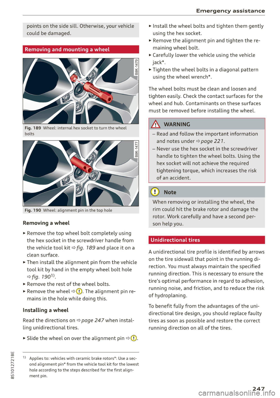
Fig. 189 Wheel: internal hex socket to turn the wheel
bolts
B8K-1477
Fig. 190 Wheel: alignment pin in the top hole
Removing a wheel
> Remove the top wheel bolt completely using
the hex socket in the screwdriver handle from
the vehicle tool kit > fig. 789 and place it ona
clean surface.
> Then install the alignment pin from the vehicle
tool kit by hand in the empty wheel bolt hole
> fig. 190".
> Remove the rest of the wheel bolts.
» Remove the wheel >(). The alignment pin re-
mains in the hole while doing this.
Installing a wheel
Read the directions on > page 247 when instal-
ling unidirectional tires.
> Slide the wheel on over the alignment pin >@.
1) Applies to: vehicles with ceramic brake rotors*: Use a sec-
ond alignment pin* from the vehicle tool kit for the lowest
hole according to the steps described for the first align-
ment pin.
> Install the wheel bolts and tighten them gently
using the hex socket.
> Remove the alignment pin and tighten the re-
maining wheel bolt.
> Carefully lower the vehicle using the vehicle
jack*.
> Tighten the wheel bolts in a diagonal pattern
using the wheel wrench*.
The wheel bolts must be clean and loosen and
tighten easily. Check the contact surfaces for the
wheel and hub. Contaminants on these surfaces
must be removed before installing the wheel.
ZA\ WARNING
— Read and follow the important information
and notes under > page 227.
— Never use the hex socket in the screwdriver
handle to tighten the wheel bolts. Using the
hex
socket will not achieve the required
tightening torque, which increases the risk
of an accident.
CG) Note
When removing or installing the wheel, the
rim
could hit the brake rotor and damage the
rotor. Work carefully and have a second per-
son help you.
U rectional tires
A unidirectional tire profile is identified by arrows
on the tire sidewall that point in the running di-
rection. You must always maintain the specified
running direction. This is necessary to ensure the
tire's optimal performance in regard to adhesion,
running noise, and friction, and to reduce the risk
of hydroplaning.
To benefit fully from the advantages of the uni-
directional tire design, you should replace faulty
tires as soon as possible and restore the correct
running direction on all of the tires.
247
Page 272 of 280
Index
Instrumenticlusten «secon + & avcnsie x 0 sucuses © a swe 10
Cleaning..... 2.0... cee eee eee eee 239
FailibGios » 2 smo $ 2 ama ge meew 4 e eM a A om 10
Me@SSageS sxasis wo onesies vv oenens « 8 coewer wx mewn 16
Operating ........ 0... cee cece eee 12
Service interval display................ 212
Switching tabs. « « ssi a «asa ss eww oo we 12
Instruments
Adjusting the lighting.................. 39
Interior LIQHtiNG secs. esses ee areunce a 6 arenes a a 39
Interior monitoring.................0 eee 24
Intermittent (windshield wipers).......... 41
Internet
referto connects « = secs ve views vo seme ¥ oe 141
IntermetiradiOnes: « «seine s x oxime + ¥ soanese % © awas 174
iPod
refer to Audi music interface....... 175,176
HTUMESAQGING & woes so aeseie + cess o + ecswoR os 164
J
Joystick function (MMI) ..............005 115
JOKED OX: s cams « yam a + earn 8 x Rem ae oe 171
JUMP Starting ces + = news < eases s aaem 3 3 Ra 248
K
KG": wcme s = mame 2 2 eeNNs ¢ 2 STS xo eee 8 2 19
Convenience opening and closing......... 27
Key not recognized.................00. 77
Key replacement <« < s sees s sees eeeeaee 19
Mechanical key.............---0005 19, 20
MESSAGES cress «sonnei o ovens 4 0) onenene 9 oem 76
Replacing the battery.................. 20
Unlocking and locking............... 21,22
WehiGle GOde « scenic 6 4 accace vo aunsaon nn enazece #0 19
Kick-down
Automatic transmission................ 86
L
Laptimer..... 2... eee eee eee 91
LATCH (securing child safety seats)......... 60
LaumeleComtrolins « sims + + ssmmn « + memo © eens 86
Leather care and cleaning............... 239
LEAVING HOMCiesn: «2 aes 6 c aewn so ee oe Ee 38
License plate bracket................--- 260
Licensing agreements (MMI)............- 194
270
Lifting points (vehicle jack).............. 246
Light/rain sensor
Headlights...............0 00. cece eee 36
Intermittent (windshield wipers) ......... 41
Lighting
EXterlor’: : wean ¢ s were « » gems so come oo eee 36
PEC OP sci « + consowe = a enesion = suomes ws eee wo He 39
Lights 2 cases ou nese 2 2 meas 2s mame 2 ewe 8 6 36
Coming/Leaving home...............4 38
Daytime running lights................. 36
Entry/exit lighting « « sii ¢ «were oo weve + oe 38
Fog lights/rear fog light(s).............. 36
Headlight flashers: s scsas + een gs anes s s 37
Headlight range control system.......... 36
HEALIGHES xerieie « scaem @ » stiesnes ovate wines 37
Interior/reading lights.................. 39
Low beam headlights.................. 36
Parking light...............00 000000 ee 36
Switching daytime running lights on and off .38
Listening to music
refer to Mediaiecs ss ecw se seves ve ee 169; 177
EOad + same 2 = suum ¢ 2 mene © E eae FY eae a 264
Locking and unlocking
By remote control... : seca .: eeea ss eves ee 21
With the convenience key............... 22
Low beam headlights.................00, 36
Luggage compartment
Bag... cee cece eet eee 66
Cover... eee eee eee 65
Increasing the'size.. 2. nsec sccsee se veee ees 66
POWEPSOURGES ecessics 1 = ssseews wo 2 eerie oo seers 63
Tie-downs ... 2... 0... cece eee 67
also refer to Luggage compartment...... 64
Luggage compartment lid................ 27
Mechanically unlocking...............-. 26
Opening and closing................00- 25
Opening from the inside in an emergency.. 27
Luggage compartment net............... 67
Lumbar support.............-.00 eee eae 46
M
Maintenance........... 0. cece eee eee 258
Maintenance intervals..............005. 212
Making an emergency call............... 134
Malfunction Indicator Lamp (MIL)......... 200
Page 277 of 280
8S1012721BE
Index
Options during a phone call............ 133
Playing Music... 2.66... cece eee eee eee 172
SGttinGSinay s « ages ss wey ee emew 2 BoM ge 139
Temperature display (outside temperature) .. 11
Temperature gauge
Coolants: s = wows s 2 aeuee so se oe eee 8 2 10
Tethering
refer to Personal hotspot.............. 142
TeXEIMESSAGES weone co eee oo een ys ees ws 135
also refer to Text messages............ 135
THeCOWNS & ssssiie ov iimsive 6 8 euinene wo wrseats 7 8 sutaens 67
Tightening specification
Wheel bolts............. 00. eee eee eee 248
Tightening specification (wheel bolts) ..... 248
THING i iscsi a annsina 6 0 anesine 6 0 arm sw ormneR 3 oo 189
tiptronic (automatic transmission) ......... 85
Tire Mobility System (tire repair set)...... 242
THFGS weeps + < coupe 2 & sous 7 = HEUOS Fo eee 2 owe 214
Low-profile tires wi... 6 ose se eee ae oe 230
Repairset..... 0... cece eee ee eee 242
REPLACING wcvws x = neuen s 2 sows + enews ee ces 244
Semnviceilifer. iv sccwae i x unaane wv aruene wo come 223
Tire pressure... 2... eee eee eee 224
Tire pressure monitoring sys-
HOW oo iva os ena os anes « wes 231,232,233
Tire pressure table................00- 226
Treadwear indicators.................. 223
Unidirectionals « = ssc = 3 sce x & aeons 216, 247
Uniform tire quality grading............ 230
Tires and wheels
Glossary of tire and loading terminology.. 217
Tires and vehicle load limits............ 227
Tone (sound)
refer to Adjusting the sound............ 193
TOOL easx ss woes os mene & % eenR & + eeDR 5 F eee 242
Top tether anchor (securing the child safety
SOAE) oo www «x ewwwns wo aovaens xo atten we atten © oa 62
Touch
refertoMMlItouch................0.. 112
TOWNE: i «: sanrace + « emoseus o © snvmmns & 0 amen © 0 enone 250
TOWING LOOP erececs ss corners vo soecens ¥ 8 were 251,252
Towing protection monitoring............. 24
TPMS
Indicator light... .......0....0022.00. 235
Tire pressure monitoring system.... 232, 233
Traffic information ......... 0... eee eee 161
Transmission malfunction (indicator light).. 87
Treble (SOUR) sexi «i scoise so inawass oo orien o 6 8 193
Turnsigitals « seas 2 5 eee gems ¢ are oe oes 37
U
Uniform tire quality grading............. 230
Unlocking and locking
By remotecontrolis « . sessic es wee eae xe 21
Using the lock cylinder................. 24
With the central locking switch.......... 23
With the convenience key............... 22
Updating stations (radio)................ 164
USB
charging pOrtis: = sew: «2 ses « e sere sc ee 63
USB stick
refer to Audi music interface....... 175,176
V
Vanity Minthoriacw + 2 cau ¢ caren w = neue 2 = nee 41
Vehicle
Care/cleaning « « sis + 2 sews x 2 ere a 8 woe 236
Dimensions ............0 cece eee e eee 263
Identification data « cox « < seme x y oem 4 2 2 263
OQUEOFSEIVICE seins © x nen 2 2 wane 2 wane 6 3 241
Raising.......... 00... eee eee eee eee 246
Unlocking anid locking: « « cess ai wows st ves 21
Vehicle battery
Charge levels s eens se cee oe ees ae oe 109
VehiGlecare cx 5 2 waza a 2 eawes & 2 eae ge 236
Vehicle'data labels: s : sacs es veea se vean se 263
Vehicle identification number............ 263
Vehicle jack................00000. 242, 248
Lifting POINTS: + « sees ss exam se ave se oes 246
Vehicle'toolU kits « « coms x « name ¢ ¢ seas 2 2 Ree 242
Ventilation. ........ 0... eee eee eee 69
Version information................000- 192
VIEW button... ... ee eee ee 12
Voice guidance
refer to Multifunction steering wheel.. 12,14
Voicemail... 6... 6c cece eee eee eee eee 137
Voice recognition system............ 14,122
Commands.......... 2.00 123
EXterOal scien sy awe s eee 2 eee @ 5 Hee 8 127:
OPCTATING’. » « momeoe © siwsenece s cueneee am ramet om 122
SettingS .... 0.0... c cece eee eee 190
VOlUMElssce « 2 sews 2 ¢ aueep 5 2 maw oo ome ae 194
275