fuel AUDI TT ROADSTER 2014 Owners Manual
[x] Cancel search | Manufacturer: AUDI, Model Year: 2014, Model line: TT ROADSTER, Model: AUDI TT ROADSTER 2014Pages: 244, PDF Size: 60.87 MB
Page 5 of 244
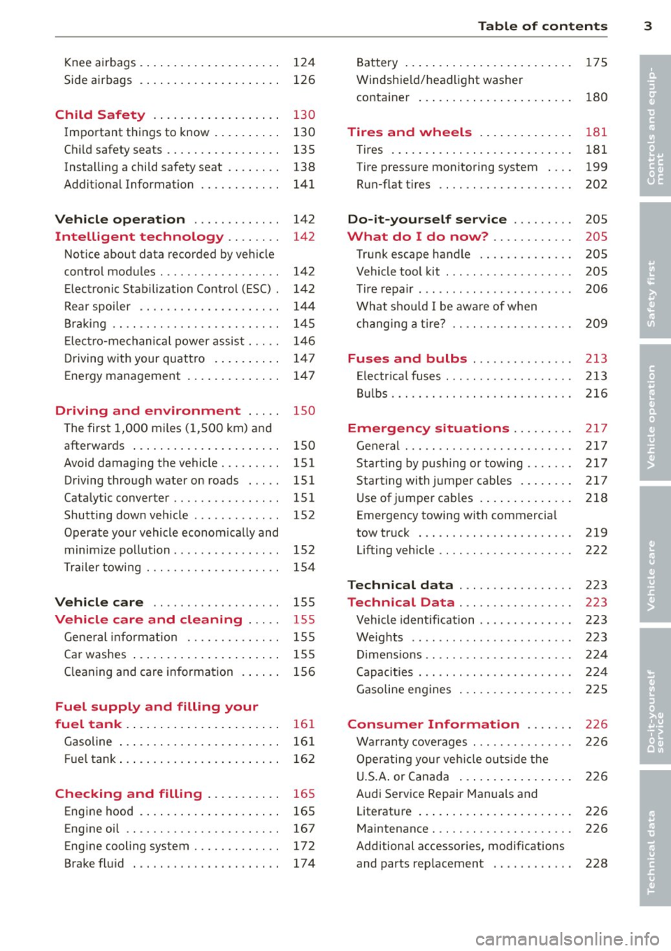
Knee airbags . . . . . . . . . . . . . . . . . . . . . 124
Side airbags . . . . . . . . . . . . . . . . . . . . . 126
Child Safety . . . . . . . . . . . . . . . . . . . 130
Important things to know ......... .
Child safety seats ................ .
Instal ling a chi ld safety seat .. .. .. . .
Additional Information ........... .
Vehicle operation ............ .
Intelligent technology .. .. .. . .
Notice about data recorded by vehicle
control modules .............. ... .
Electronic Stabilization Control (ESC) .
Rear spoiler ................ ... . .
Braking ........................ .
E lect ro-me chan ical power assis t ... . .
D riving w ith your quattro ......... .
Energy management ............. .
Driving and environment .....
The first 1,000 miles (1,500 km) and
afterwards .............. .. .. .. . .
Avoid damaging the vehicle ........ .
Driving through water on roads ... . .
Catalytic converter ............... .
Shutting down vehicle ............ .
Operate your vehicle economically and
minimize pollution ............... . 130
135
138
141
142
142
142
142
144
145
146
1 47
147
1 5 0
150
151
151 151
152
15 2
Tra iler towing . . . . . . . . . . . . . . . . . . . . 154
Vehicle care . . . . . . . . . . . . . . . . . . . 155
Vehicle care and cleaning . . . . . 155
General information . . . . . . . . . . . . . . 155
Car washes . . . . . . . . . . . . . . . . . . . . . . 155
Cleaning and care information . . . . . . 156
Fuel supply and filling your
fuel tank . . . . . . . . . . . . . . . . . . . . . . .
16 1
Gasoline . . . . . . . . . . . . . . . . . . . . . . . . 161
Fuel tank. . . . . . . . . . . . . . . . . . . . . . . . 162
Checking and filling . . . . . . . . . . . 16 5
Engine hood . . . . . . . . . . . . . . . . . . . . . 165
Eng ine oil . . . . . . . . . . . . . . . . . . . . . . . 167
Eng ine cooling system............. 172
Brake fluid ...................... 174
Table of contents 3
Battery . . . . . . . . . . . . . . . . . . . . . . . . . 175
Windshield/headlight washer
container . . . . . . . . . . . . . . . . . . . . . . . 180
Tires and wheels ........... .. .
Tires ..... .. .... .. . .. .......... .
Tire pressure monitoring system ... .
Run-flat tire s .. .. ............... .
Do-it-yourself service ........ .
What do I do now? ........... .
Trunk escape handle ............. .
Vehicle tool kit .... .............. .
T ire repai r .... ... .. ............. .
What should I be aware of when
h . t
' 7 c angmg a ire .................. .
Fuses and bulbs .. .. .. ..... ... .
El ectr ical fuses . .. .. ............. .
Bulbs .......................... .
Emergency situations ........ .
General ........................ .
Starting by pushing or towing ...... .
Starting with jumper cables ....... .
U se of jump er cables ............. .
Emergency towing with commercia l
tow truck ...................... .
Lifting vehicle .. .. ............... . 181
181
199
202
205
205
205
205
206
209
213
213
216
217
217
217
217
218
219
222
Technical data
. . . . . . . . . . . . . . . . . 223
Technical Data . . . . . . . . . . . . . . . . . 223
Vehicle identification . . . . . . . . . . . . . . 223
Weights . . . . . . . . . . . . . . . . . . . . . . . . 223
Dimensions . . . . . . . . . . . . . . . . . . . . . . 224
Capacities . . . . . . . . . . . . . . . . . . . . . . . 224
Gasoline engines . . . . . . . . . . . . . . . . . 225
Consumer Information . . . . . . . 226
Warranty coverages . . . . . . . . . . . . . . . 226
Operating your vehicle outside the
U.S. A. or Canada . . . . . . . . . . . . . . . . . 226
Audi Service Repair Manuals and
Literature . . . . . . . . . . . . . . . . . . . . . . . 226
Maintenance. . . . . . . . . . . . . . . . . . . . . 226
Additional accessories, modifications
and parts rep lacement . . . . . . . . . . . . 228
•
•
Page 11 of 244
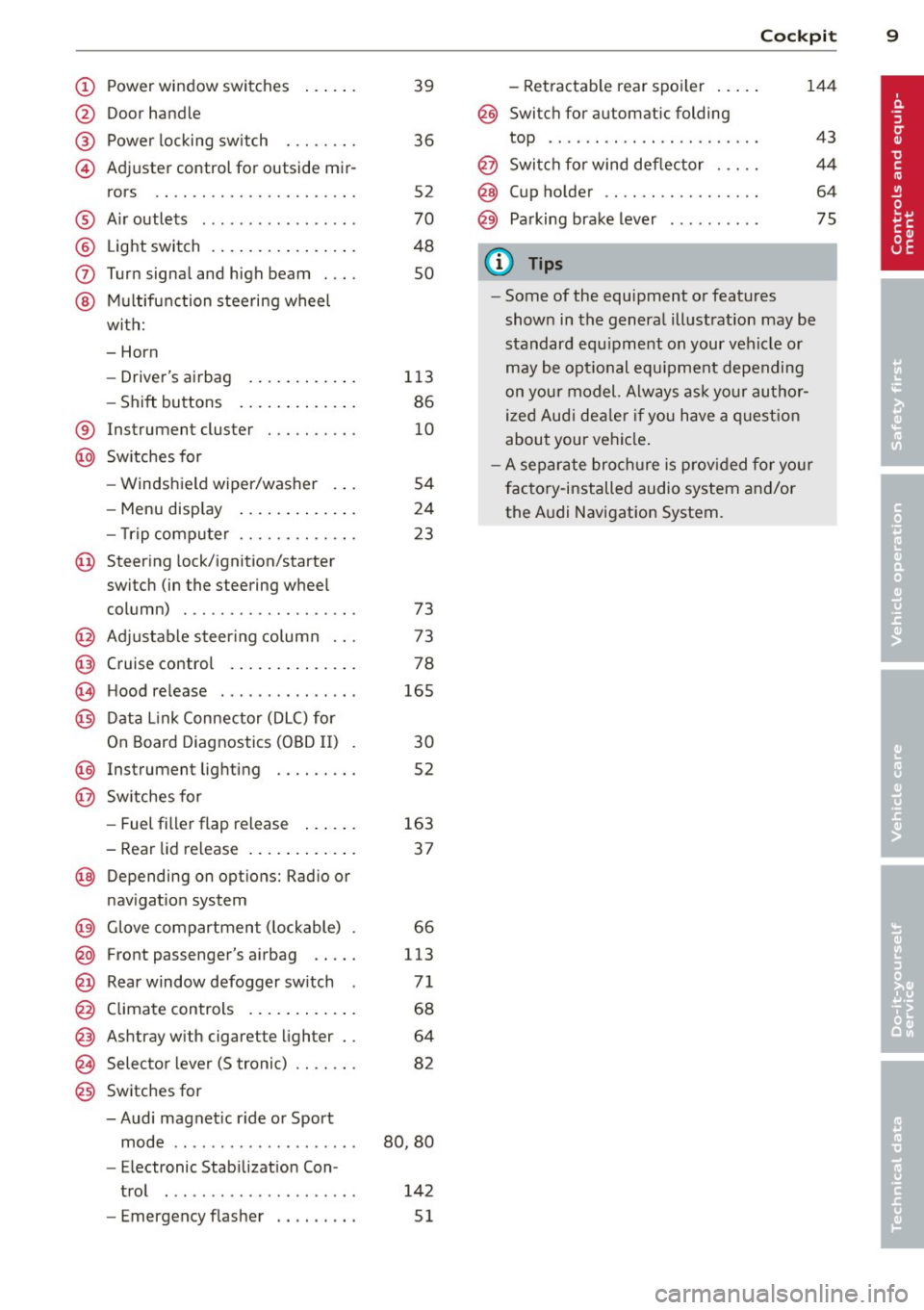
(!) Power window switches
@
®
©
Door handle
Power locking sw itch
Adjuster control for outside mir- rors ... . ............. .... .
® Air outlets ............... . .
@ Light switch . ... .... ... .. .. .
(J) Turn signa l and high beam . .. .
@ Mu ltifunction stee ring wheel
with:
- Horn
- Drive r's ai rbag .... ... .. .. .
- Shift buttons ..... ... .. .. .
® Instrument cluster
@ Sw itches for
- Windshield wiper/washer
- Menu disp lay ..... ... .. .. .
39
36
S2
70
48
so
113
86
10
S4
24
- T rip computer . . . . . . . . . . . . . 23
© Steering lock/ignition/starter
switch (in the steering wheel
column) . . . . . . . . . . . . . . . . . . . 73
@ Adjustab le s teer ing column . . . 73
@ Cruise control . . . . . . . . . . . . . . 78
€3J H ood re lease . . . . . . . . . . . . . . . 165
@ Data L ink Connector (DLC) for
On Board Diagnostics ( OBD II) 30
@ Instrument lighting . . . . . . . . . 52
@ Switches for
- Fuel filler flap release 163
- Rea r lid re lease . . . . . . . . . . . . 3 7
@ Depending on opt ions: Rad io or
nav igat ion system
@ Glove compar tment ( lockable) 66
@ Front passenger's a irbag . . . . . 113
@ Rear window defogger sw itch 7 1
@ Climate controls . . . . . . . . . . . . 68
@ Ashtray w ith cigarette lighter . . 64
@ Selecto r l ever (5 troni c) . . . . . . . 82
@) Switches for
- Audi magnet ic r ide or Sport
mode . . . . . . . . . . . . . . . . . . . . 80, 80
- Electronic Stab ilizat ion Con-
tro l . . . . . . . . . . . . . . . . . . . . . 142
- Emergency flasher . . . . . . . . . 51
Cockpi t 9
- Retractable rear spo iler .. ...
@ Switch for automatic folding
144
top . ... .. .. .. .. . .. .... ... .
@ Swi tch for wind deflector .... .
@ C up ho lder .. .. .. .......... .
@ Pa rking brake lever
(D Tips
- Some of the equipment or features
show n in the genera l illustration may be
standard equ ipme nt on your vehicle or
may be opt ional equ ipment depending
on you r model. Always as k yo ur au tho r
ized Aud i de aler if you have a quest ion
abou t your vehi cle.
- A separate bro ch ure is p rov ided for yo ur
facto ry-installed audio system and/or
the A udi Navigation System.
43
4 4
64
75
Page 12 of 244
10 Instruments and warning/indicator lights
Instruments and warning/indicator Lights
Instruments
Instrument cluster and controls
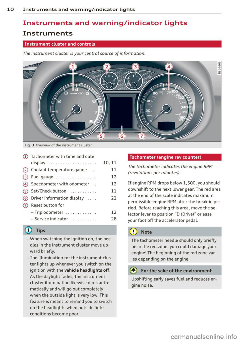
The instrument cluster is your central source of information.
Fig. 3 Overv iew of the inst rument cluster
(D Tachometer with time and date
dis play .. .... ..... ........ .
@ Coolant temperature gauge .. .
® Fuel gauge ................ .
© Speedometer with odometer ..
® Set/Check button ..... ... .. .
@ Driver information display
(?) Reset button for
- Trip odometer .......... .. .
- Service indicator
@ Tips
10 ,11
11
12
12
11
22
12
28
- When switching the ignition on, the nee
dles in the instrument cluster move up
ward briefly.
- The illumination for the instrument clus
ter lights up whenever you switch on the
i gnition with the
vehicle headlights off .
As the daylight fades, the instrument
cluster illumination likewise dims auto
matically a nd will go out completely
when the outside light is very low. This
feature is meant to remind you to switch
on the head lights when outside light
conditions become poor .
Tachometer (engine rev counter)
The tachometer indicates the engine RPM
(revolutions per minutes) .
en 0
~
~
"'
If engine RPM drops below 1,500, you should
downshift to the next lower gear. The red area
at the end of the scale indicates maximum
permissible engine RPM after the br eak-in pe
riod. Before reaching this area, move these
lector lever to position "D (Drive)" or ease
your foot off the acce lerator pedal.
(D Note
The tachometer needle should only briefly
be in the red zone: you could damage your
engine! The beg inning of the red zone var
i es depending on the engine.
@ For the sake of the environment
Upshifting early saves fuel and reduces en
gine noise.
Page 14 of 244
12 Instruments and warning/indicator lights
Fuel gauge
The fuel gauge works only when the ignition is
on . When the needle reaches the red area, the
warning light in the instrument cluster will il
luminate ¢
page 20 00']. Time to refuel!
The total ta nk capacity of your vehicle is listed
in
¢ page 224
CD Note
Never run the tank completely dry! An ir
regula r supply of fue l can cause engine
m isfiri ng and fuel could enter into the ex
haust system. The catalyt ic converter
could then overheat and be damaged.
Speedometer with odometer
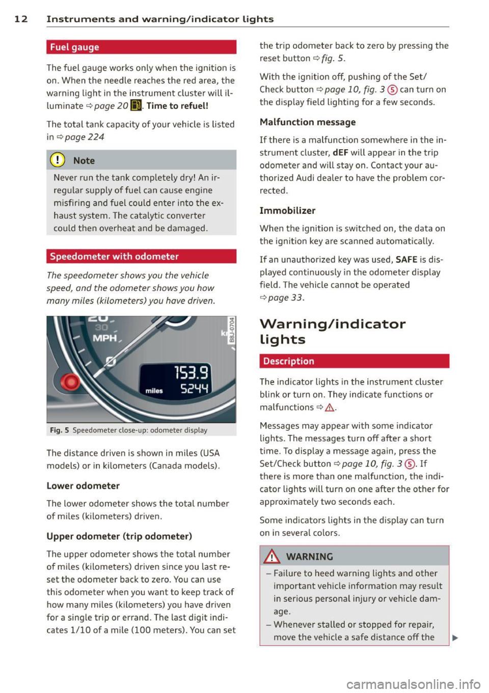
The speedometer shows you the vehicle
speed , and the odometer shows you how
many miles (kilometers) you have driven.
Fig . S Spee domete r close -up: odometer display
The dis tance driven is shown in miles (USA
models) or in kilometers (Canada models) .
Lower odometer
The lower odometer shows the total number
of miles (kilometers) driven.
Upper odometer (trip odometer)
The upper odometer shows the total number
of mi les (kilometers) driven since you last re
set the odometer back to zero. You can use
this odometer wh en you want to keep track of
how many miles (kilometers) you have driven
for a sing le trip or errand. The last digit indi
ca tes 1/10 of a mile (100 me ters). You can se t the trip odometer
back to zero by pressing the
reset button
¢ fig. 5.
With the ign ition off, pushing of the Set/
Check button ¢
page 10, fig . 3 ® can turn on
the display fie ld lighting for a few seconds.
Malfunction message
If there is a malfunct ion somewhere in the in
strument cluster,
dEF will appear in the trip
odometer and will stay on. Contact your au
thorized Audi dea ler to have the problem cor
rected .
Immobilizer
When the ignition is sw itched on, the data on
the ignition key are scanned automat ically .
If an unauthor ized key was used,
SAFE is dis
played continuously in the odometer display
field . The vehicle cannot be operated
¢ page 33.
Warning/indicator
Lights
Description
T he ind icator lights in the instrument cluster
blink or turn on . They indicate funct ions or
malfunctions ¢
,&.
Messages may appear with some indicator
lights . The messages turn
off after a short
time . To display a message again, press the
Set/Check button¢
page 10, fig . 3 ® · If
there is more than one ma lfunction, the indi
cator lights will turn on one after the other for
approximat ely two seconds each.
Some indicators lights in the display can turn
on in severa l colors.
A WARNING
=
- Failure to heed warning lights and other
important vehicle information may result
in ser ious personal in jury or vehicle dam
age.
- Whenever stalled or stopped for repair,
move the vehicle a safe distance
off the
Page 16 of 244
14 Instruments and warning/indicator lights
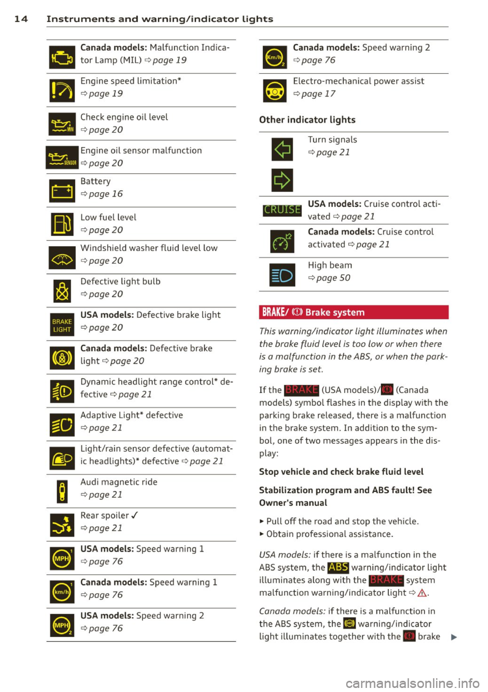
111'!!1 Canada models: Malfunction Indica
mil tor Lamp (M IL) ¢ page 19
I'm Engine speed limitation*
1111111 ¢ page 19
• Check engine o
il level ¢ page20
• Engine
oil sensor malfunction ¢ page20
•
II
Battery
¢page 16
Low fuel level
¢page20
• Windshie
ld washer fluid level low ¢ page20
l:J
Defective light bulb
¢page20
•
USA models : Defective brake light
¢page 20
Cl
Canada models: Defective brake
light
¢ page 20
II
Dynamic headlight range control* de-
fective ¢
page 21
El
Adaptive L ight* defective
¢page 21
m
Light/rain sensor defective (automat-
ic head lights)* defective ¢
page 21
B
Audi magnetic ride
¢page 21
•
Rear spoiler../
¢page 21
~
USA models : Speed warning 1
¢page 76
•
Canada models: Speed warning 1
¢page 76
•
USA models : Speed warning 2
¢page 76
Canada models: Speed warning 2
¢page 76
Electro-mechanical power assist
¢ page 17
Other indicator lights
II
II
CRUIS
•
Turn signals
¢page 21
USA models: Cruise control acti
vated ¢
page 21
Canada models: Cruise control
activated ¢
page 21
High beam
¢page 50
BRAKE/ (CD) Brake system
This warning/indicator light illuminates when
the brake fluid level is too low or when there
is a malfunction in the ABS, or when the park
ing brake is set.
If the - (USA models)/ . (Canada
models) symbo l flashes in the disp lay with the
parking brake released, there is a malfunction
in the brake system. In addition to the sym
bol, one of two messages appears in the dis
play:
Stop vehicle and check brake fluid level
Stabilization program and ABS fault! See
Owner's manual
.,. Pull off the road and stop the vehicle.
.,. Obtain p rofessional assistance.
USA models: if there is a ma lfunction in the
ABS system, the
m;B warning/ind icator light
illuminates along with the - system
malfunction warning/indicator light¢
A.
Canada models: if there is a malfunction in
the ABS system, the~ warning/i ndicator
lig ht i llum inates together with the. bra ke ..,_
Page 18 of 244
16 Instruments and warning/indicator lights
If the I (USA models) JII (Canada models)
indicator light does not go out, or if it illumi
nates wh ile you are driv ing, or if it starts to
blink, then there is a ma lfunction somewhere
in the system . If the light does not illuminate
when you switch on the ignition, this also
means there is a malfunction .
A WARNING
If you have a malfunction in the safety sys
tems, contact your authorized Audi dealer
immediate ly. Otherwise the safety sys
tems may not wo rk properly in an acci
dent.
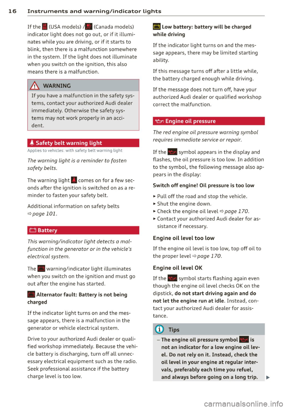
4 Safety belt warning light
Applies to vehicles: with safety belt warning light
The warning light is a reminder to fasten
safety belts.
The warning light . comes on for a few sec
onds after the ignit ion is switched on as a re
m inder to fasten your safety belt.
Addit ional information on safety belts
Q page 101.
0 Battery
This warning/indicator light detects a mal
function in the generator or in the vehicle's
electrical system.
The. warning/ind icator light illuminates
when you sw itch on the ignit ion a nd must go
out after the engine has started.
• Alternator fault: Battery is not being
charged
If the indicator light turns on and the mes
sage appears, there is a ma lfunction in the
generator or vehicle electr ical system.
Drive to your authorized Audi dealer or quali
fied workshop immediately . Because the vehi
cle battery is discharging, turn off all unnec
essary electrical equipment such as the radio.
Seek professional ass istance if the battery
charge level is too low.
(•) Low battery: battery will be charged
while driving
If the indicator l ight turns on and the mes
sage appears, there may be limited starting
ability.
If this message turns off after a litt le while,
the battery charged enough while driving.
If the message does not turn off, have your
authorized Aud i dealer or qualified workshop
correct the malfunction.
requires immediate service or repair.
If the . symbol appears in the disp lay and
flashes, the oil pressure is too low. In add ition
to the symbol, the following message also ap
pears in the display:
Switch off engine! Oil pressure is too low
.,. Pull off the road and stop the vehicle.
• Shut the eng ine down.
.,. Check the engine oil level¢ page 170.
.,. Contact your authorized Aud i dealer for as-
sistance if necessary.
Engine oil level too low
If the engine oil leve l is too low, top off oil to
the proper level¢
page 170.
Engine oil level OK
If the . symbo l starts flashing again even
though the engine oi l level checks OK on the
dipstick,
do not start driving again and do
not let the engine run at idle.
Instead, con
tact your authori zed Aud i dealer for ass is
tance.
(D Tips
- The engine oil pressure symbol. is
not an indicator for a low engine oil lev
el. Do not rely on it. Instead, check the
oil level in your engine at regular inter
vals, preferably each time you refuel,
and always before going on a long trip.
Page 21 of 244
Instrument s and warnin g/indic ator ligh ts 19
-USA models: If the la warning light,
the
G1 warning light and the m:IJ warn
ing light come on together, t he rear
wheels could lock up first under hard
braking. Rear wheel lock-up can cause
loss of vehicle control and an accident .
Have your vehicle repai red immediately
by you r autho rized Aud i dea ler or a qua li
fied workshop. Drive slowly and avoid
sudden, hard brake applications .
-Canada models: If the brake warn ing
light ., the
&J warn ing light and the
ABS warning light
[IJ come on together,
the rear wheels could lock up first under
hard braking. Rear wheel lock-up can
cause loss of vehicle control and an acci
dent . Have you r vehicle repaired immed i
ately by your authorized Audi dealer or a
qualified wo rkshop . Dr ive slowly and
avo id sudden, hard brake applicat ions.
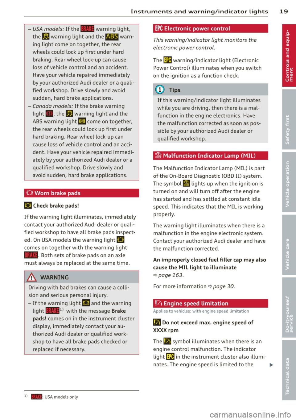
( 0) Worn brake pads
riJ Che ck brake pad s!
If the warn ing light illum inates, immediately
contact your authorized A udi dealer or quali
f ied workshop to have all brake pads inspect
ed. O n USA models the wa rning lig ht
riJ
comes on togethe r wi th the warn ing light
la . Both sets of b ra ke pads on an axle
must always be replaced at the same time .
A WARNING
Driving with bad brakes can cause a colli
sion and serious personal injury.
- If the warning light riJ and the warning
light
lai1 ) w it h the message Brake
pads !
comes on in the instr ument cluster
display, immediately contact your au
tho rized Aud i dea le r or qualified work
shop to have a ll brake pads checked or
replaced if necessary .
1) - : USA mod els on ly
-
EPC Electronic pow er control
This warning/indicator light monitors the
electronic power control.
The ~ warning/indicator light (Electronic
Power Control) illuminates when you switch
on the ignition as a function check .
@ Tips
If this warning/ indicato r light illum inates
while you are driving, then there is a mal
funct ion in the engine electronics . Have
the malfunct ion corrected as soon as pos
sible by your authori zed A udi dealer or
q ualified works hop .
~ Malfunction Indicator lamp (MIL )
The Ma lfun ction Indicator Lamp ( MIL) is par t
of the On -Board Diagnostic (OBD II) system.
The symbo l
fl lights up when the ignition is
turned on and will turn off after the eng ine
has started and has settled at constant idle
speed . This indicates that the MIL is work ing
proper ly.
The warning light illuminates when there is a
malfu nction in the eng ine electron ic system .
Contact your a uthorized Audi dea ler and have
the malfunction corrected.
An improperly closed fuel filler cap may also
cause the MIL l ight to illum inate
c::> page 163.
For more information c::> page 30 .
!?) Engine speed limitation
App lies to vehicles : wi th engine speed limitatio n
(m Do not e xceed ma x. engine speed of
XXXX rpm
The (Ill symbol illuminates when there is an
engine contro l ma lf u nction . The indicator
li ght ~ in the instrument cl uster a lso illumi-
nates. The engine speed is limited to the .,.
Page 22 of 244
20 Instruments and warning /indicator lights
speed displayed in the driver information sys
tem . Keep in mind that the engine speed will
not exceed the va lue disp layed in the driver in
formation system, for example when down
shifting.
Please go to an authorized Audi dea ler or oth
er qualified workshop to have the ma lfunction
repaired.
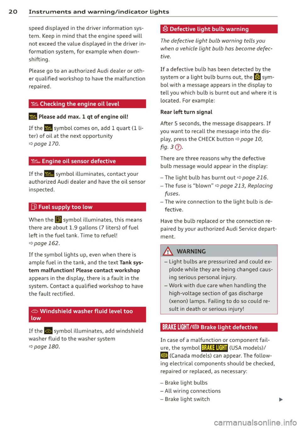
~ . Checking the engine oil level
II Please add max . 1 qt of engine oil!
If the II symbol comes on, add 1 quart (1 li
ter) of oil at the next opportunity
¢page 170.
~ ... Engine oil sensor defective
If the II symbol illuminates, contact your
author ized Audi dealer and have the oil sensor
inspected .
Bi) Fuel supply too low
When the 001 symbol illuminates, this means
there are about 1.9 gallons (7 liters) of fuel
left in the fuel tank. Time to refuel!
¢ page 162.
If the symbol lights up, even when there is
ample fuel in the tank, and the text
Tank sys
tem malfunction! Please contact workshop
appears in the display, there is a fault in the
system. Contact a qualified workshop to have
the fault rectified.
If the -symbol illum inates, add w indshield
washer f luid to the washer system
¢page 180.
~ Defective light bulb warning
The defective light bulb warning tells you
when a vehicle light bulb has become defec
tive.
If a defective bulb has been detected by the
system or a light bulb burns out,
the m sym
bol w ith a message appears in the display to
te ll you which bulb is burnt out and where it is
located. For example :
Rear left turn signal
After 5 seconds, the message disappears. If
you want to recall the message into the dis play, press the CHECK button
¢ page 10,
fig. 3
(J) .
There are three reasons why the defective
bulb message would appear in the display:
- The light bu lb has burnt out
¢page 216.
-The f use is "blown" ¢ page 213, Replacing
fuses .
-The wire connection to the light bulb is de-
fective.
Have the bulb replaced or the connect ion re
paired by your authorized Aud i Service depart
ment .
A WARNING
-
-Light bulbs are pressurized and could ex
p lode while they are being changed caus
ing serious personal injury.
- Work with due care when handling the
high-vo ltage section of gas discharge
(xenon) lamps. Failing to do so could re
sult in death or serious injury!
BRAKE LIGHT!<®> Brake light defective
In case of a malfunction or component fail-
ure, the symbol (USA models)/
It:$
repaired or replaced, as necessary:
- Brake light bulbs
- All wiring connections
- Brake light switch
Page 25 of 244
Trip computer
Introduction
The trip computer gives you information on
current and average fuel mileage, average
speed, fuel range and driving time .
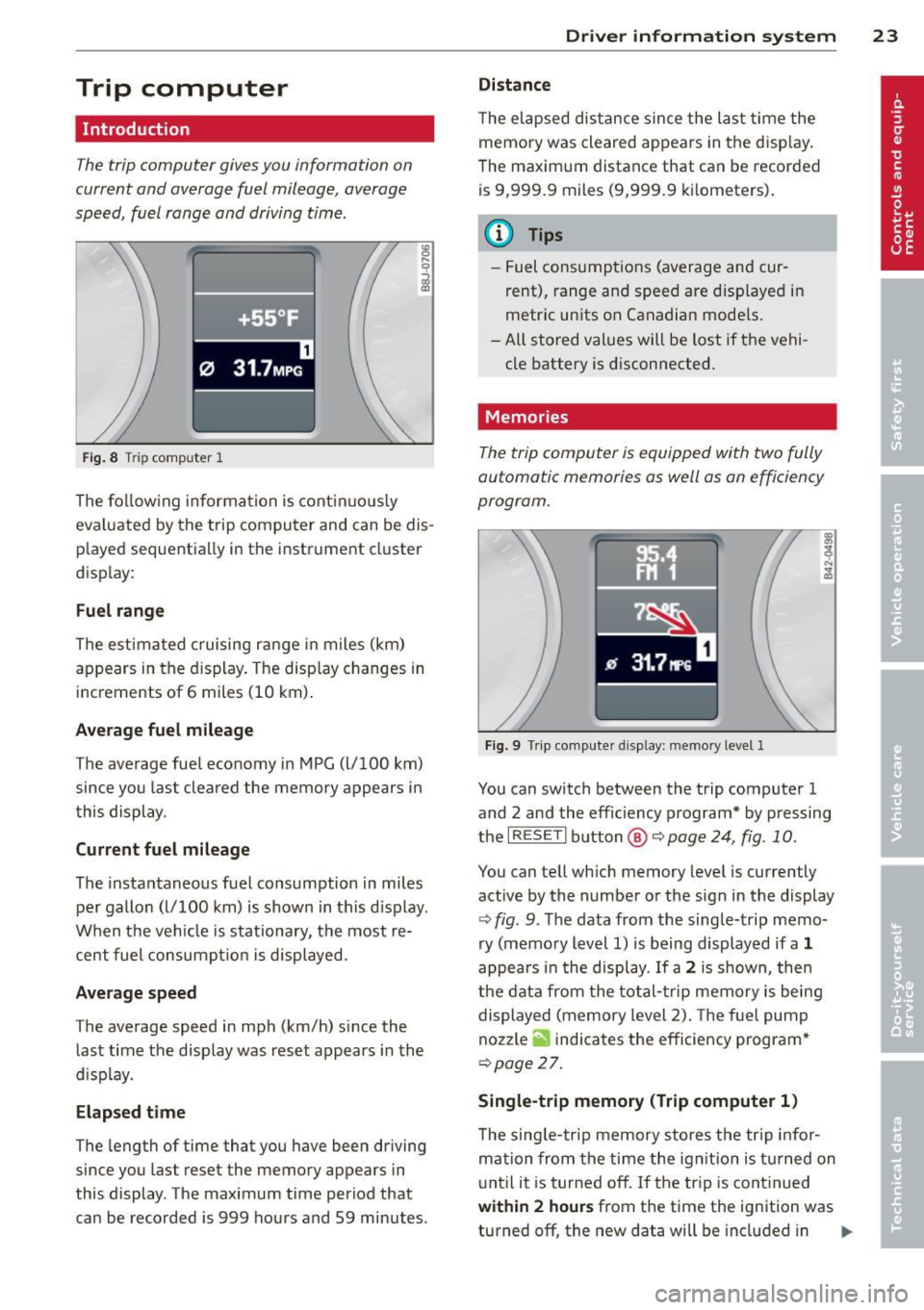
Fig. 8 T rip comp ute r 1
The fo llow ing informa tion is cont inuo usly
eva luated by the trip compu ter and can be dis
p layed sequentia lly in the instrument cl uster
d isplay:
Fuel range
The estimated c ruising ra nge in miles (km)
appears in the d isplay . The disp lay changes in
increments of 6 miles (10 km) .
Average fuel mileage
The average fue l economy in MPG (l/ 100 km)
since you last clea red the memory appears in
t his display .
Current fuel mileage
The instantaneous fuel consumption in miles
pe r gallon (l/ 100 km) is shown in this d isp lay .
When the ve hicle is stationary, the most re
cent fuel consumpt io n is displayed.
Average speed
The average speed in mph (km/h) since the
last time the display was reset appears i n the
d isp lay.
Elap sed t ime
The length of time that you have been driving
since you las t reset the memory appears in
this display . The maximum t ime period that
can be recorded is 999 ho urs and 59 minutes .
Driver in formation system 23
Distance
The elapsed dis tance sin ce the las t time the
memory was cleared appears in the d isp lay .
T he maxim um distance that can be recorded
is 9 ,999.9 miles (9,999 .9 k ilometers) .
(D Tips
- Fuel consump tions (average and cur
rent), range and speed are disp layed in
metric un its on Canadian mode ls.
- All sto red val ues wil l be lost if t he vehi
cle battery is d isconnected .
' . Memories
The trip computer is equipped with two fully
automatic memories as well as on efficiency
progrom.
Fi g. 9 Trip co mputer d isplay: memo ry level 1
You can switch between the trip computer 1
and 2 and the efficiency program* by pressing
the
I R ES ET I button @ c::> page 24, fig . 10 .
You can tell wh ich memory leve l is currently
active by the number or the sign in the display
c::> fig . 9. The data from the single-trip memo
ry (memo ry level 1) is being displayed if a
1
appea rs i n t he display . If a 2 is shown, then
the data from the total- trip memory is being
displayed (memory level 2). The f ue l pump
nozzle
ii indicates the efficiency program *
c::>poge 27.
Single-trip memory (Trip computer 1 )
The sing le -t rip memory stores the tr ip info r
ma tion from the time the ig nition is tu rned on
u nt il it is tur ned off. If the tr ip is cont inued
within 2 hour s from the time the ignit ion was
turned off, the new data will be included in ..,.
Page 26 of 244
24 Driver information system
the calculation of the current trip informa
t ion. If the trip is interrupted for
more than 2
hours
the memory is reset automatica lly.
Total -trip memory (Trip computer 2)
Unlike the sing le-trip memory, the total-trip
memory is not reset automatically. This per
mits you to evaluate your dr iving data for the
entire period between manual resets.
Efficiency program*
The effic ien cy program can help you to use
less fuel
~ page 2 7.
Operation
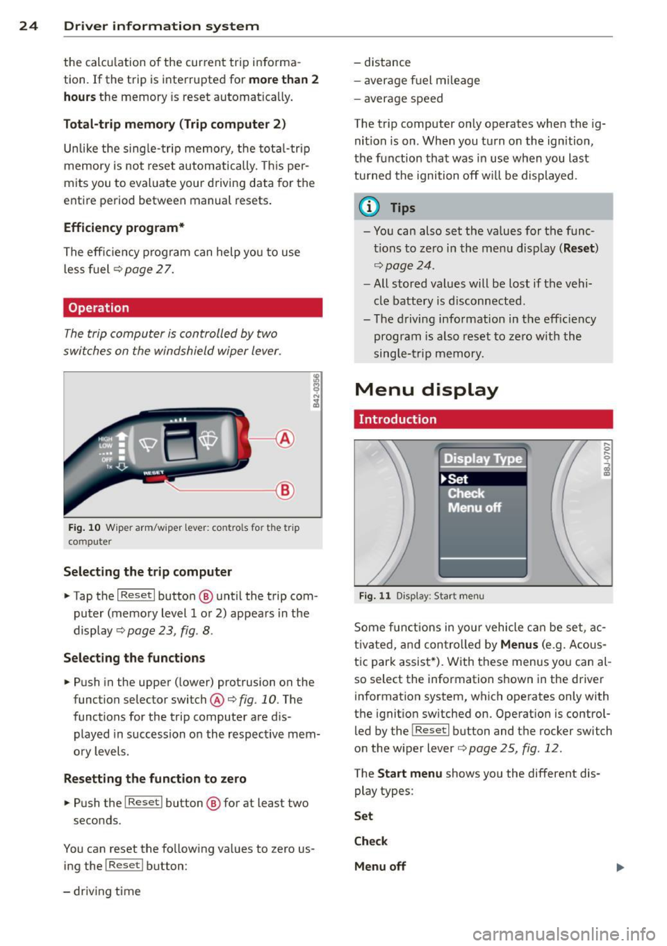
The trip computer is controlled by two
switches on the windshield wiper lever.
-----------< @
Fig. 10 W iper arm/w iper lever: con tro ls for t he trip
compute r
Selecting the trip computer
"Tap the I Reset I button @ until the trip com
puter (memory level 1 or 2) appears in the
display ¢
page 23, fig . 8.
Selecting the functions
" Push in the upper (lower) protrusion on the
function selector switch @
q fig. 10. The
functions for the trip computer are d is
played in succession on the respective mem
ory levels.
Resetting the function to zero
" Push the I Reset I button @ for at least two
seconds.
You can reset the fo llowing values to zero us
ing the
I Reset I button :
- driving time -
distance
- average f uel mileage
- average speed
The t rip computer only operates when the ig
nition is on. When you turn on the ignition,
the function that was in use when you last
turned the ignition off will be displayed .
(D Tips
-You can also set the values for the func
tions to zero in the menu display
(Reset )
qpage24 .
-All stored values will be lost if the vehi
cle battery is disconnected .
- The driving information in the efficiency
program is a lso reset to zero with the
single-trip memory.
Menu display
Introduction
Display Type
•set
iF'Cf t -,,., ==
Menu off
Fig. 11 D isplay: Sta rt men u
Some funct ions in yo ur vehicle can be set , ac
t ivated, and controlled by
Menus (e.g. Acous
tic park assist *). With these menus you can al
so select the information shown in the driver
information system, which operates only with
the ignition switched on. Operation is control
led by the
! Reset I button and the rocker switch
on the wiper lever
q page 25, fig . 12.
The Start menu shows you the different dis
play types:
Set
Check
Menu off