oil reset AUDI TT ROADSTER 2015 Owners Manual
[x] Cancel search | Manufacturer: AUDI, Model Year: 2015, Model line: TT ROADSTER, Model: AUDI TT ROADSTER 2015Pages: 244, PDF Size: 60.74 MB
Page 27 of 244
Set Clock ¢ page 2 5
Computer¢ page 25
Acoustic par k assist* ¢ page 79
Speed warning ¢ page 77
Language ¢
page 2 5
Units (distance, fue l consump-
tion, temperature) ¢
page 25
Tire press ure moni toring
c> page 198
Lap timer* c>page 28
Lighting* ¢ page 48
Wiper (service pos it io n)
¢page 56
Window c> page 40
Doors (unlo ck ing and locking
mode, for example Auto- lock)
¢ page 34, c> page 34
Check
Service c> page 28
Chassis numbe r c> page 2 22
Engine oil temperature*
¢
page 26, c> page 26
Registe red keys ¢ page 32
Menu off
All of the messages shown in
vehicles withou t menu display ap-
pe ar o n the display screen.
Navigating the menu
Use the rocker switch on the windshield wiper
lever and the
I Reset ! button to operate the
menu and carry out inquiries and selections.
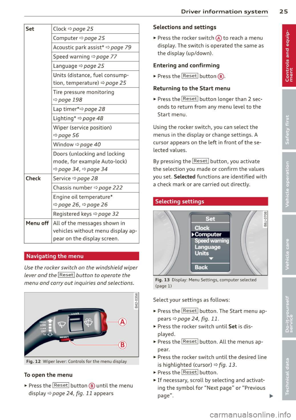
~-- @
Fig. 1 2 Wiper leve r: Controls for the men u disp lay
To open the menu
.. Press the I Reset ! button @ until the menu
display
i=> page 24 , fig . 11 appears
Dr iver in formation system 25
Selections and settings
.. Press the rocker switch @to reac h a men u
disp lay. The swi tch is operated the same as
the display (up/down).
Entering and confirming
.,. Press the I Reset I butto n @ .
Returning to the Start menu
.. Press the I Reset I button longer tha n 2 sec
onds to return from any menu level to the
Sta rt menu .
U sing the rocker switc h, you can select the
menus in the display or change settings. A
cursor appea rs on the left in front of these
lected values .
By pressing the
I Reset! button, you activate
the selection you made or confirm the values
you set.
Selected fu nctions are identified wit h
a check mark or ar e car ried out directly .
Selecting settings
Fig. 13 D isplay: Menu Sett ings, co mpute r selected
(page
l)
Se lect you r settings a s foll ows:
.,. Press the
I Reset I butto n. The Sta rt menu ap
pears ¢
page 24 , fig . 11 .
.. Press the rocker switch unt il Set is dis
played .
.. Press the
I Reset I butto n. All the menu s a p
pe a r .
.. Press the rocker switch until the desire d line
is highlig hted (curso r)
¢ fig . 13 .
.. Press the I Reset I button.
.. If necessary, scro ll by selecting and activat
ing the symbol for "Next page" o r "Previous
page" .
~
Page 28 of 244
26 Driver information system
When you have selected the Computer menu
and activated it by pressing the
I Reset! but
ton, two computer levels appear (computer 1
and computer 2). Now you have to select the
level you want using the rocker switch and ac
tivate it w ith the
! Reset I button .
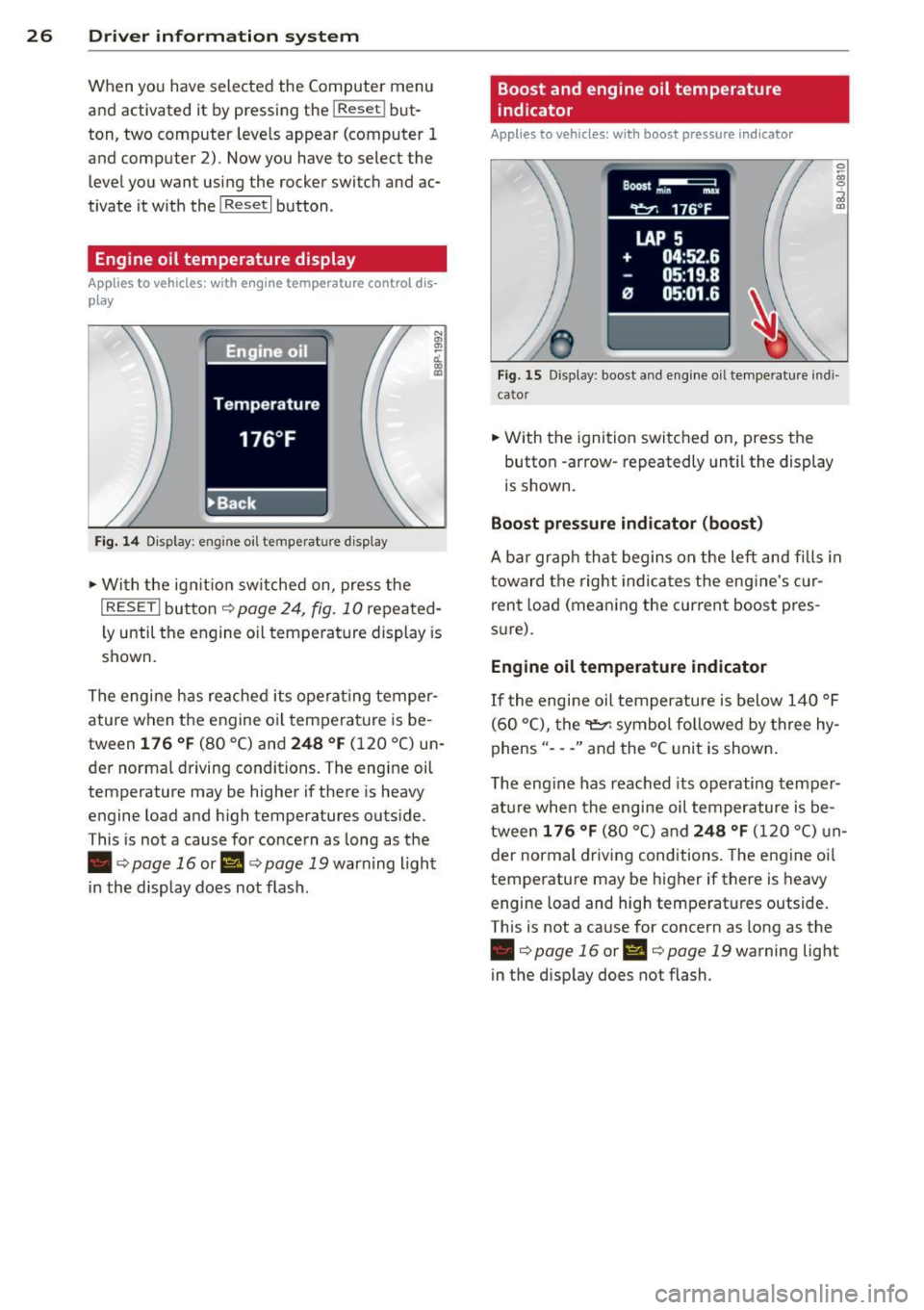
Engine oil temperature display
Applies to vehicles: with engine temperature control dis
play
Engine oil
Temperature
176 °F
•Back
Fig. 14 Display: engine o il temperature d isp lay
• With the ign ition sw itched on, press the
N
"' l!! a'.. 0) (D
I RESET I button¢ page 24, fig. 10 repeated
ly until the engine oil temperature display is
shown.
The engine has reached its operating temper
ature when the engine oil temperature is be
tween
176 °F (80 °C) and 248 °F (120 °C) un
der normal driving conditions. The engine oil
temperature may be higher if there is heavy
engine load and high temperatures outside.
This is not a cause for concern as long as the
• ¢
page 16 or Ill¢ page 19 warn ing light
in the display does not flash.
Boost and engine oil temperature
indicator
Applies to vehicles: with boost pressure indicator
0 /xi 0
;;i OJ
Fig. 15 Display: boost and engine oi l temperature indi·
ca tor
• With the ignition switched on, press the
button -arrow· repeatedly until the display
is shown.
Boost pressure indicator (boost)
A bar graph that begins on the left and fills in
toward the right indicates the eng ine's c ur
rent load (meaning the current boost pres
s ur e).
Engine oil temperature indicator
If the engine oil temperature is below 140 °F
(60 °C), the
"t::?1 symbol followed by three hy
phens"- --" and the °C unit is shown .
The engine has reached its operating temper
ature when the engine oil temperature is be
tween
176 °F (80 °() and 248 °F (120 °() un
der normal driving conditions. The engine oil
temperature may be higher if there is heavy
engine load and high temperatures outside.
This is not a cause for concern as long as the
• ¢page 16 orl'I c::;,page 19 warning light
in the display does not flash.
Page 30 of 244
28 Driver information system
-The fuel economy messages are not dis
played in every instance, but rather in in
terva ls over a period of ti me.
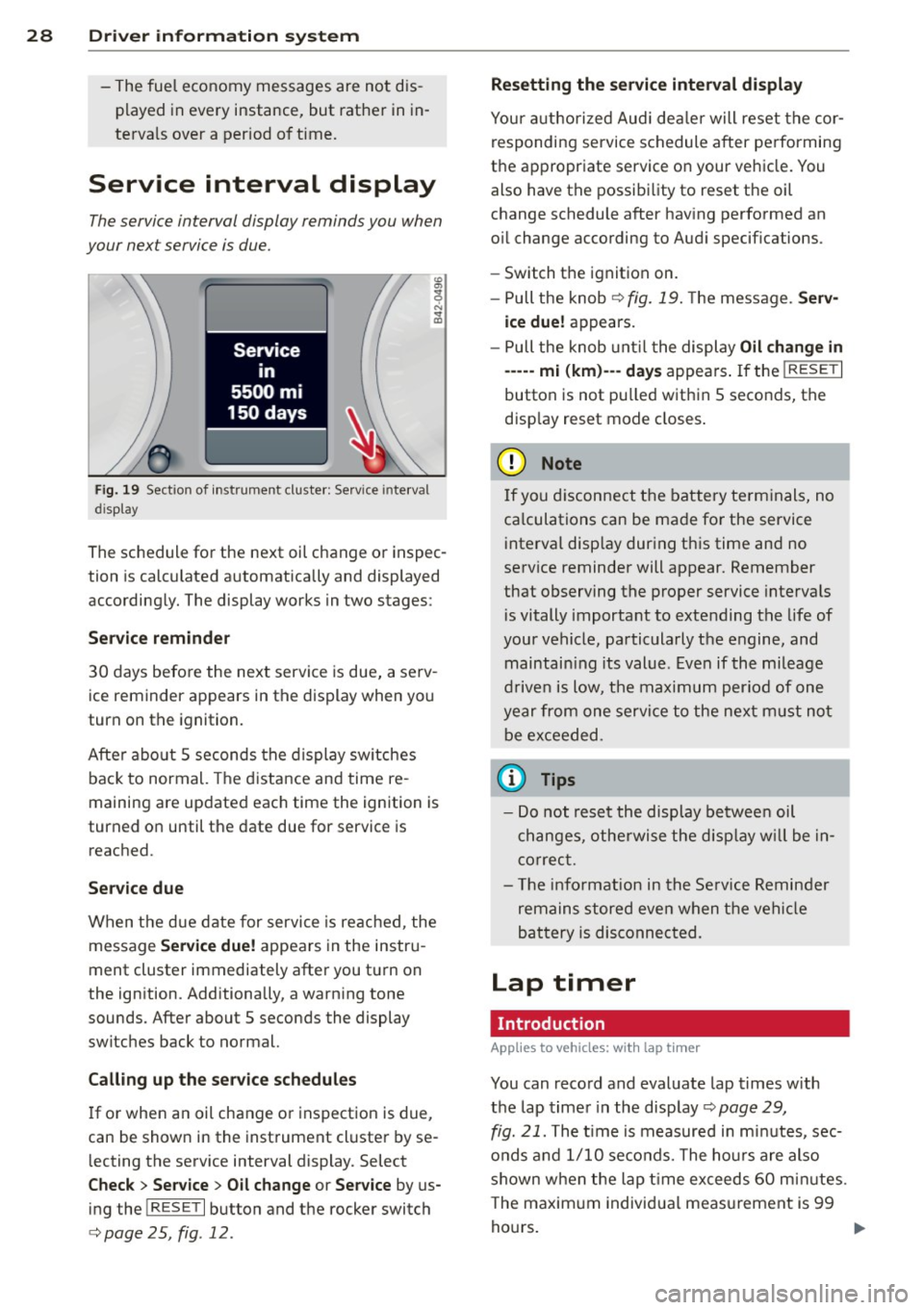
Service interval display
The service interval display reminds you when
your nex t service is due.
Fig. 19 Sect ion of instrument cluster: Serv ice in terva l
d isp lay
The schedule for the next oil change or inspec
tion is calculated automatically and displayed
accordingly. The display works in two stages :
Service reminder
30 days before the next service is due, a serv
ice reminder appears in the display when you
turn on the ignition.
After about
5 seconds the display switches
back to normal. The distance and time re
maining are updated each time the ignition is
turned on until the date due for service is
reached.
Service due
When the due date for service is reached , the
message
Service due! appears in the instru
ment cluster immediately after you turn on
the ignition. Additionally, a warning tone
sounds . After about
5 seconds the display
switches back to normal.
Calling up the service schedules
If or when an oil change or inspection is due,
can be shown in the instrument cluster by se
lecting the serv ice interval display. Select
Check > Service > Oil change or Service by us
ing the
! R ES ET I button and the rocker switch
c> page 25 , fig . 12.
Resetting the service interval display
Your authorized Audi dealer will reset the cor
responding service schedule after performing
the appropriate service on your veh icle. You
also have the possibility to reset the oil
change schedule after having performed an
o il change according to Audi specifications.
- Switch the ignition on.
- Pull the knob
c> fig. 19. The message. Serv-
ice due!
appears.
- Pull the knob until the display
Oil change in
-----mi (km)---day s appears . If the I RESET I
button is not pulled within 5 seconds, the
disp lay reset mode closes.
(D Note
If you disconnect the battery terminals, no
ca lculations can be made for the service
interval display during this time and no
service reminder will appear. Remember
that observing the proper service intervals
i s vitally important to extending the life of
your vehicle, particularly the engine, and
maintain ing its value . Even if the mileage
driven is low, the maximum period of one
year from one service to the next must not
be exceeded.
'
(D Tips
-Do not reset the display between oil
changes, otherwise the display w ill be in
correct.
- Th e information in the Service Reminder
remains stored even when the vehicle
battery is disconnected.
Lap timer
I ntrod ucti on
App lies to vehicles: wit h lap timer
You can record and evaluate lap times with
the lap timer in the display c>page
29,
fig. 21. The time is measured in minutes, sec
onds and
1/10 seconds. The hours are also
shown when the lap t ime exceeds
60 min utes .
T he maximum individual measurement is 99
hours. ..,.
Page 215 of 244
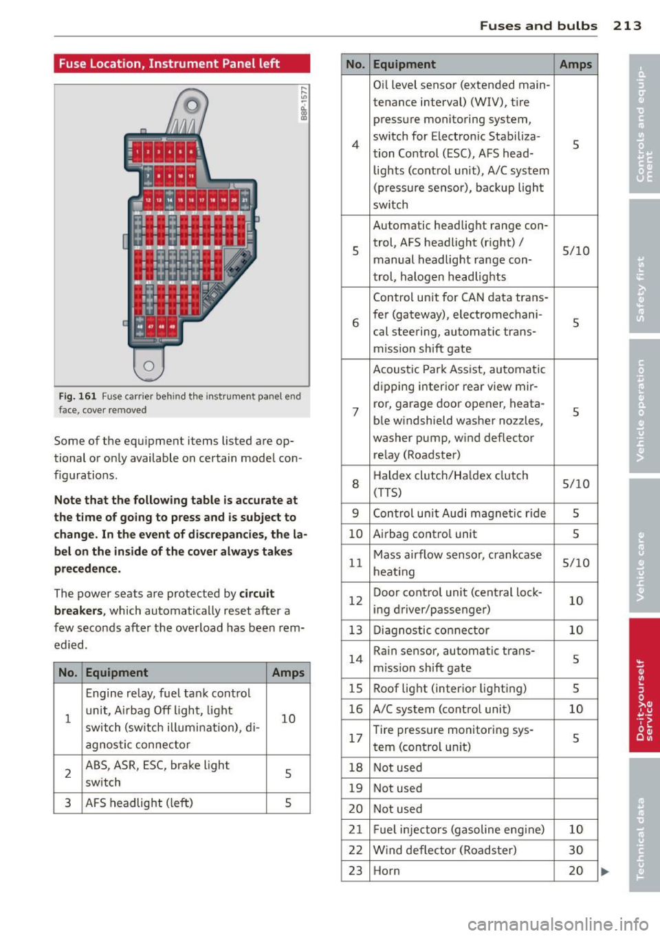
Fuse Location, Instrument Panel left
0
Fig. 161 Fuse carrier behind the instrument panel end
face, cover removed
Some of the eq u i prnent items listed a re op
tional or only available on certain model con
f igurations.
Note that the following table is accurate at
the time of going to press and is subject to
change. In the event of d iscrepancies, the la
bel on the in side of the cover always takes
precedence .
The power seats are protected by circuit
breakers ,
which automatically reset after a
few seconds after the overload has been rem
ed ied.
No. Equipment Amps
Engine relay, fuel tank cont ro l
1
unit, A irbag Off light, light
10 switch (sw itch illumi nation), di-
agnostic connector
2
ABS, ASR, ESC, brake light
5 switch
3 AFS headlight (left) 5
No.
4
5
6
7
8
9
10
11
12
13
14
15
16
17
18
19
20
21 22
23
Fuses and bulbs 213
Equipment Amps
Oil level sensor (extended main-
tenance interval)
(WIV), t ir e
press ure monitoring system,
sw itch for Electron ic Stabiliza-
5 tion Control (ESC), AFS head-
lights (control unit), A/C system
(pressure sensor), backup light
sw itch
Automatic headlight range con- trol, AFS headlight (right) /
5/10
manual headlight range con-
trol, halogen headlights
Control unit for CAN data trans-
fer (gateway), electrornechani-
5 cal steering, automatic trans-
miss ion shift gate
Acoustic Park Assist, automatic
d ip ping interior rear
view rnir-
ror, garage door opener, heata-
5 ble windshield washer nozzles,
washer pump, w ind deflector
relay (Roadster)
H aldex clutch/Ha ldex clutch
5/10 (TTS)
Control un it Audi magnetic ride
5
A irbag contro l unit 5
Mass airflow sensor, crankcase 5/10
heating
Door control unit (central lock -
10 ing driver/passenger)
Diagnostic connector
10
Rain sensor, automatic trans-
5 miss ion sh ift gate
Roof light (interior lighting)
5
A/C system (contro l unit) 10
Tire pressure monitoring sys -
5 tern (control un it)
Not used
Not used
Not used
Fuel injectors (gasoline eng ine)
10
Wind deflector (Roadster) 30
Horn 20
Page 238 of 244
236 Index
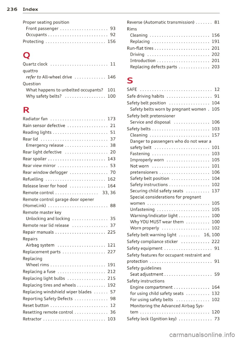
Proper seating position Front passenger . . . . . . . . . . . . . . . . . . . . 93
Occupants . .... ............ .. .... .. 92
Protecting . .. .... .. ... .... .. .. .. .. . 156
Q
Quartz clock . . . . . . . . . . . . . . . . . . . . . . . . 11
quatt ro
refer to All-wheel dr ive .... .. .. .... . 146
Question What happens to unbe lted occupants? 101
Why safety be lts? . . . . . . . . . . . . . . . . . 100
R
Radiator fan .... . ...... ... .. .. .... . 173
Ra in sensor defect ive .... .... .... ..... 21
Reading lights .... ..... ...... .. .. .. .. 51
Rear lid . .. .. .... .... ..... .. .. .. .. .. 37
E mergency release . . . . . . . . . . . . . . . . . . 38
Rear lig ht defective . . . . . . . . . . . . . . . . . . 20
Rear spoiler . . . . . . . . . . . . . . . . . . . . . . . . 143
Rear v iew mirro r . . . . . . . . . . . . . . . . . . . . . 53
Rear window defogger . . . . . . . . . . . . . . . . 70
Refue lling ... ... . ...... ... .. .. .... . 162
Release lever for hood .......... .. ... 164
Remote control . . . . . . . . . . . . . . . . . . 33, 36
Remote control garage door opene r
( H omelink) . . . . . . . . . . . . . . . . . . . . . . . . . 88
Remote master key Un lock ing and locking ..... .. .. .. .. . . 35
Remote rea r lid release . .... .. .. .. .. . . 37
Repair manua ls .. .. ..... ... .. .. .... . 225
Repairs Airbag system ............ ... .. .. . 12 1
Replacement parts ........... .. .. .. . 227
Replacing Wheel rims .... .. ..... ... .. .. .... . 19 1
Replacing a fuse .... ... .. .. .. .. .. .. . 212
Replacing light bulbs ....... .. .. .... . 215
Replacing tires a nd wheels ... .. .. .. .. . 19 2
Replacing w indshield wiper blades .. .. . . 57
Report ing Safety Defects . ... .. .. .... . . 98
Reset b utton . ............. .. .. .. .. .. 12
Resett ing remote control .... .. .. .. .. . . 36
Retractor .... ... ... .... ... .. .. .... . 103 Reve
rse (A utomat ic transm iss ion) . ... .. . 81
Rims Cleaning .. .... .. ............. .... 156
Rep lac ing . .. .. .. ............. .. .. 191
Run-fl at t ires .. .. .. .. .. ...... ... .. .. 201
Driving ....... .. .. ... ........... . 202
Introduction ..... ................ . 201
Replac ing defects pa rts ......... .. .. 203
s
SAFE .. ..... ... .. .. ... ........... .. 12
Saf e driving habits ... ... ..... ... .. .. . 91
Safety be lt pos ition ............. .... 104
Safety be lts worn by pregnan t women 105
Safety be lt pretensioner
Se rv ice and d isposal ... .. ... ..... .. 106
Safety be lts . .. .. .. ............. .. .. 103
Cleaning .. .. .. .. ... ...... .... .... 157
Danger to passengers who do not wear a
safety belt .. .. .. .......... ...... . 101
Fastening ... .. .. ... .. .. ... ..... .. 103
Improperly worn . ................. 105
Not worn . .... .. ............. .... 101
pretensioners .. .. ............. .... 106
Safety be lt pos ition .. .. ..... ... .. .. 104
Safety i nstr uctions . .... ..... ... .. .. 102
Securing child safety seats . ... .. .. .. 137
Spec ial considerations for pregnant
women ... .... .. .. ............... 105
U nfastening ... ... ................ 105
Warning/ind icator light ............ . 100
Why YOU MUST wea r them .. .. .. .. .. 100
Worn p rope rly . .. ............. .. .. 102
Safety be lt warning light . . . . . . . . . 16, 100
S afety comp liance s ticker ..... ... .. .. 222
Safety eq uipme nt .. ................ .. 91
Safety features for occ upant restraint and
protection .. .... .. ............. .... . 91
Safety gu idelines
Seat adjustment. . . . . . . . . . . . . . . . . . . . 59
Safety instr uctions
E ngine compartment ... ... ..... .. .. 164
for using ch ild safety seats ...... .. .. 132
F or usi ng sa fe ty belts .......... .. .. 102
Monito ring the Advanced Airbag Sys -
tem . ... .. .... .. .. ... .. ..... ... .. 120
Safety lock (Ignition k ey) . . . . . . . . . . . . . . 73