wheel alignment AUDI TT ROADSTER 2015 Owners Manual
[x] Cancel search | Manufacturer: AUDI, Model Year: 2015, Model line: TT ROADSTER, Model: AUDI TT ROADSTER 2015Pages: 244, PDF Size: 60.74 MB
Page 192 of 244

190 Tires and wheels
Tire service life
The service life of tires depends on a lot of
different things including proper installation
and balancing, correct tire pressure and driv
ing style.
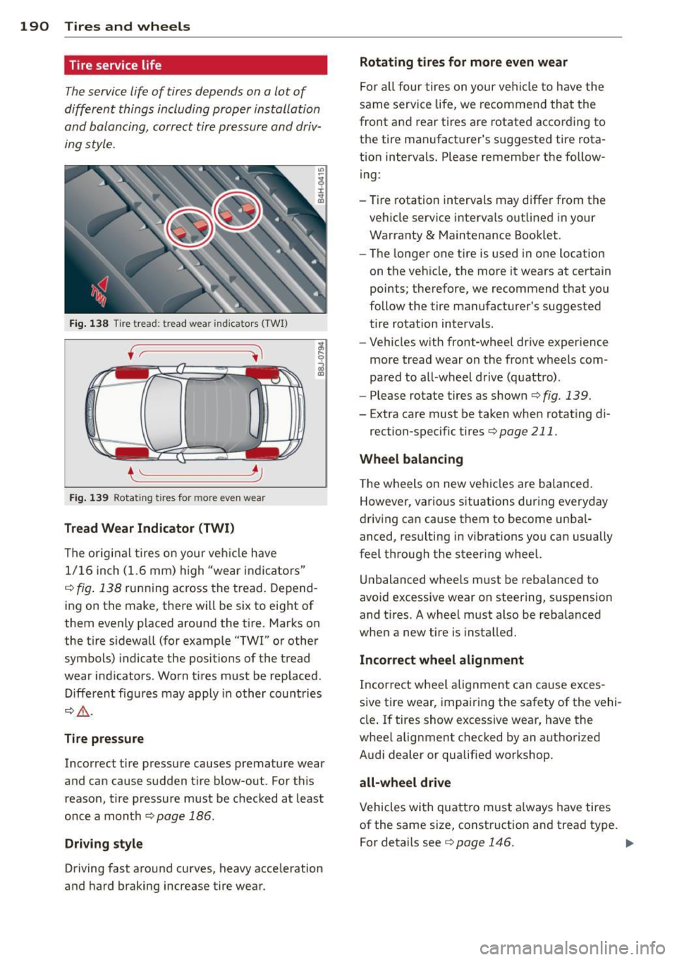
Fig. 138 Tire tread: tre ad wea r ind icators (TWI)
f ~----~
~ ..__ ____ __,
Fig. 139 Rotating t ires for more ev en wea r
Tread Wear Indicator (TWI)
The origina l tires on your veh icle have
1/16 inch (1.6 mm) high "wear indicators"
c::> fig . 138 running across the tread. Depend
i ng on the make, there will be six to eight of
them evenly placed around the tire. Marks on
the tire sidewa ll (for example "TWI" or other
symbols) indicate the positions of the tread
wear ind icators . Worn tires must be replaced .
Different figures may apply in other countries
c::> & .
Tire pressure
Incorrect tire pressure causes premature wear
and can cause sudden t ire blow-out. For th is
reason, tire pressure must be checked at least
once a month
c::> page 186.
Driving style
Driving fast around curves, heavy acceleration
and hard braking increase tire wear.
Rotating tires for more even wear
For all four tires on your vehicle to have the
same service life, we recommend that the
front and rear tires are rotated according to
the tire manufacturer's suggested tire rota
tion intervals. Please remember the follow
ing :
- Tire rotation intervals may differ from the
vehicle service interva ls outlined in your
Warranty
& Maintenance Booklet.
- The longer one tire is used in one location
on the vehicle, the more it wears at certain
points; therefore, we recommend that you
follow the tire manufacturer's suggested
tire rotation intervals .
- Vehicles with front-wheel drive experience
more tread wear on the front wheels com
pa red to all-wheel drive (quattro) .
- Please rotate tires as shown
c::> fig. 139.
-Extra care must be taken when rotating di-
rection-specific tires
c::> page 211 .
Wheel balancing
The wheels on new vehicles are balanced.
However, various situations during everyday
driving can cause them to become unbal
anced, re sulting in vibrat ions you can usually
feel through the steer ing wheel.
Unbalanced wheels must be rebalanced to
avoid excessive wear on steering, suspension
and tires. A wheel must also be rebalanced
when a new tire is installed.
Incorrect wheel alignment
Incorrect wheel alignment can cause exces
sive tire wear, impairing the safety of the veh i
cle. If tires show excessive wear, have the
whee l alignment checked by an authori zed
Audi dealer or qualified workshop.
all-wheel drive
Vehicles with quattro must always have tires
of the same size, construction and tread type .
For details see
c::> page 146 . ..,.
Page 206 of 244

204 What do I do now ?
What do I do now?
Trunk escape handle
In case of an emergency, the rear lid can be
opened from the inside using the trunk es
cape handle.
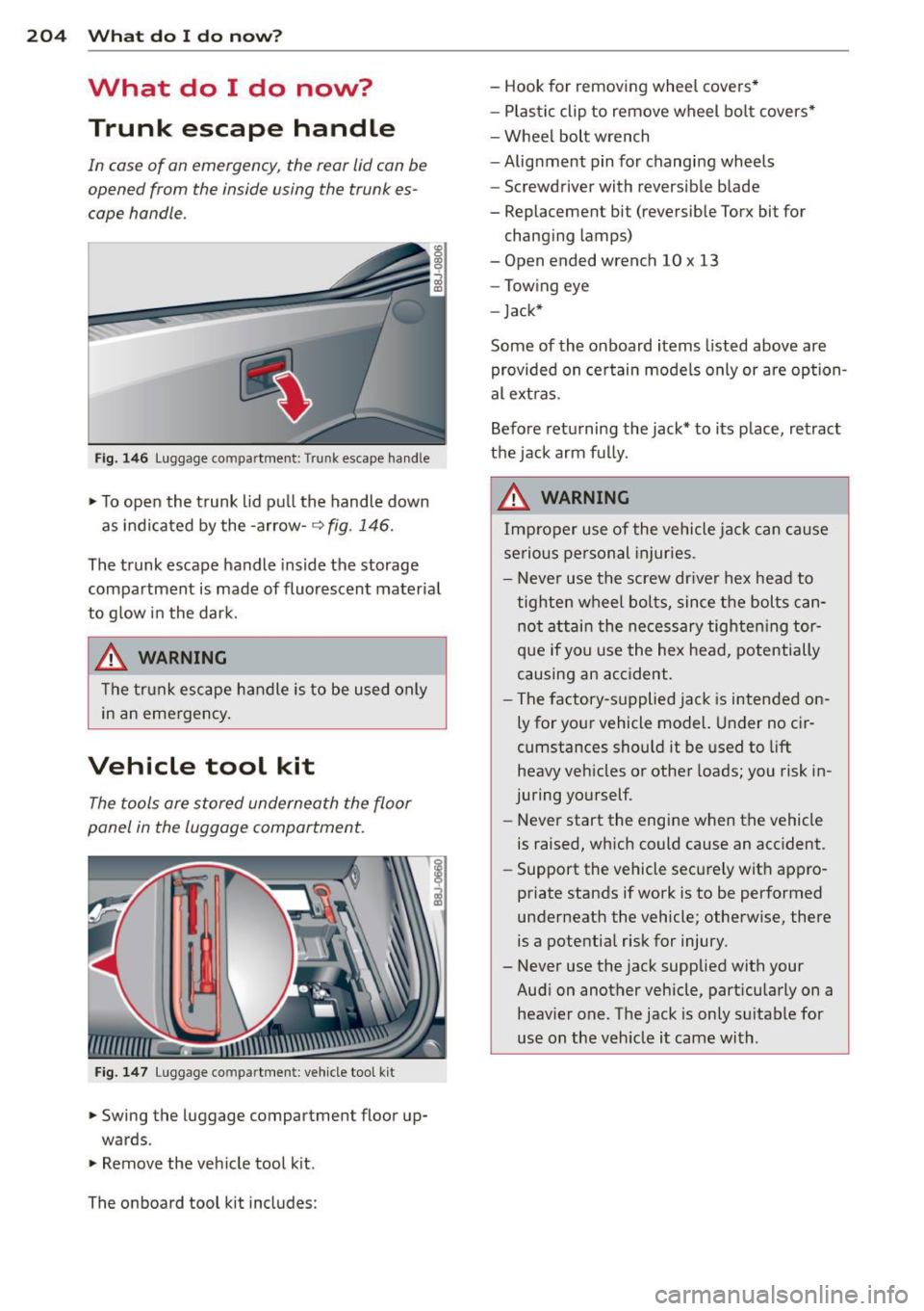
Fig. 1 46 Luggage compartment: Trunk escape handle
... To open the trunk lid pu ll the handle down
as indicated by the -arrow-~
fig. 146.
The trunk escape handle inside the storage
compartment is made of fluorescent materia l
to g low in the dark.
A WARNING
The trunk escape handle is to be used only
in an emergency.
Vehicle tool kit
The tools are stored underneath the floor
panel in the luggage compartment.
Fig. 1 47 Luggage co mpa rtment : veh icle too l kit
... Swing the luggage compartment floor up
wards .
... Remove the veh icle tool k it.
The on board tool kit includes: -
Hook for removing wheel covers *
- Plastic clip to remove wheel bo lt covers•
- Wheel bolt wrench
-Alignment pin for changing wheels
- Screwdriver with reversible blade
- Replacement bit (reversible Torx bit for
chang ing lamps)
- Open ended wrench 10 x 13
- Towing eye
- Jack*
Some of the on board items listed above are
provided on certain mode ls only or are option
al ext ras.
Before returning the jack* to its place, retract
the jack arm fully .
A WARNING
Im proper use of the vehicle jac k can cause
serious personal injuries .
- Never use the screw driver hex head to tighten wheel bo lts, since the bolts can
not attain the ne cessary tighten ing tor
que if you use the hex head, potentially
causing an accident.
- The factory-supplied jack is intended on ly for your vehicle model. Under no cir
cumstances should it be used to lift
heavy vehicles or other loads; you risk in
juring yourself.
- Never start the engine when the vehicle
is raised, wh ich could cause an acc ident.
- Support the vehicle secure ly wit h appro
priate stands if work is to be performed
underneath the vehicle; otherwise, there
is a potential risk for injury.
- Never use the jack supplied with your
Audi on another vehicle, part icularly on a
heavier one. The jack is only su itable for
use on the veh icle it came with .
Page 212 of 244

210 What do I do now?
slip and cause an injury if it does not
have sufficient hold on the vehicle.
- A soft or unstable surface under the
jack may cause the vehicle to slip off
the jack. Always provide a firm base for
the jack on the ground . If necessary,
use a sturdy board under the jack.
- On hard, slippery surface (such as tiles)
use a rubber mat or similar to prevent
the jack from slipp ing .
- To help prevent injury to yourself and
your passengers:
- Do not raise the vehicle unti l yo u are
sure the jack is securely engaged.
- Passengers must not remain in the ve
hicle when it is jacked up.
- Make sure that passengers wait in a
safe p lace away from the vehicle and
well away from the roadway and traffic.
- Make sure jack position is correct, ad
just as necessa ry and then continue to
ra ise the jack .
(D Note
A floor jack or the pads on the hoist arms
must
not be posit ioned at the points
shown
-arrows- .
Taking the wheel off
Follow these instructions step-by-step for
changing the wheel.
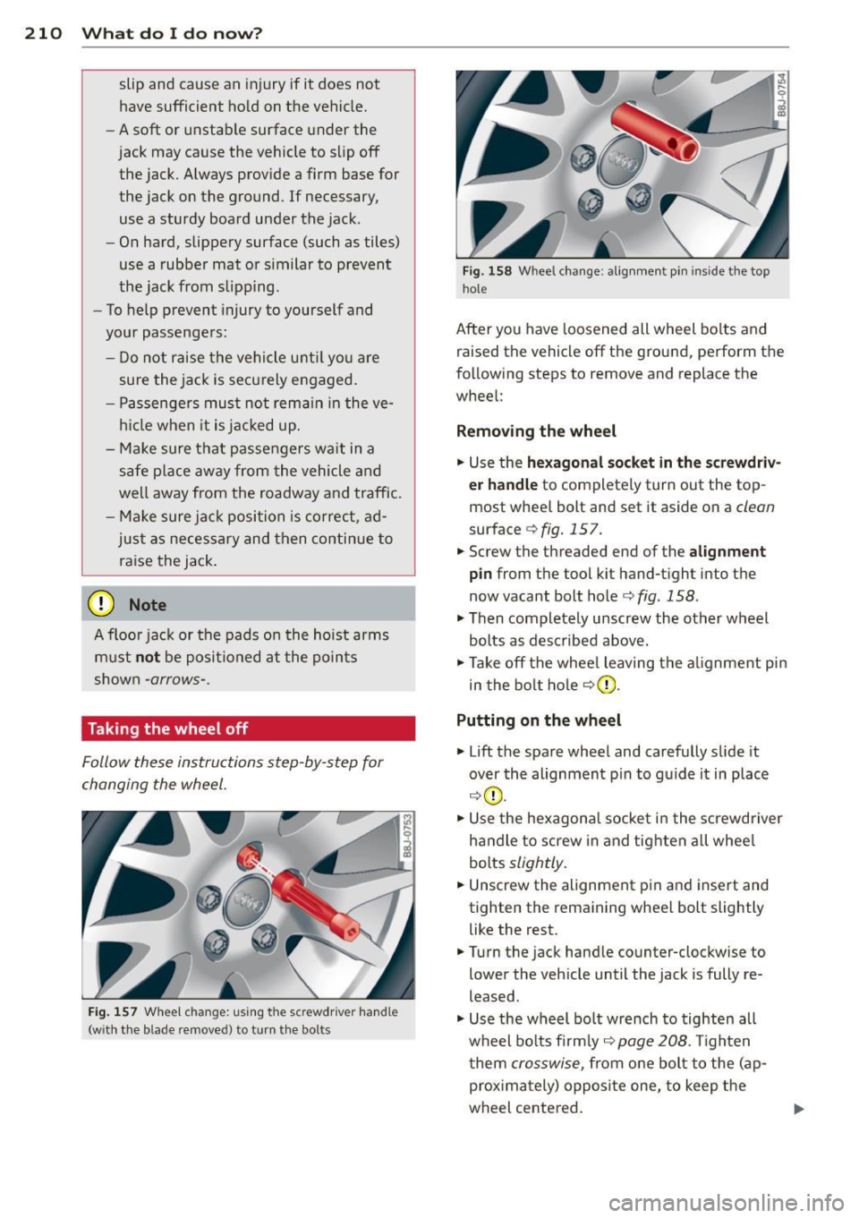
Fig. 157 Wheel ch an ge: us ing the sc rewdrive r hand le
(w ith the b lade removed) to turn the bolts
Fig. 158 Whee l change : alignmen t pin inside the top
hol e
After you have loosened all wheel bolts and
raised the vehicle off the ground, perform the
following steps to remove and replace the
wheel:
Removing the wheel
.,. Use the hexagonal socket in the screwdriv
er handle
to completely turn out the top
most whee l bolt and set it aside on a
clean
surface c;, fig. 15 7.
.,. Screw the threaded end of the
alignment
pin from the tool kit hand-tight into the
now vacant bolt hole <=>
fig. 158 .
.,. Then completely unscrew the other wheel
bolts as described above.
.,. Take off the whee l leaving the alignment pin
in the bolt hole
c;,(D .
Putting on the wheel
.,. Lift the spare wheel and carefully s lide it
over the alignment p in to guide it in place
c;,(D .
.,. Use the hexagonal socket in the screwdriver
handle to screw in and tighten all whee l
bolts
slightly .
.,. Unscrew the alignment p in and insert and
tighten the remaining wheel bolt slightly like the rest .
.,. Turn the jack handle counter-clockwise to
lower the vehicle until the jack is fully re
leased .
.,. Use the wheel bo lt wrench to tighten all
wheel bolts firmly ,=:,
page 208 . Tighten
t hem
crosswise, from one bolt to the ( ap
proximately) opposite one, to keep the
wheel centered.