interior lights AUDI TT ROADSTER 2016 Owners Manual
[x] Cancel search | Manufacturer: AUDI, Model Year: 2016, Model line: TT ROADSTER, Model: AUDI TT ROADSTER 2016Pages: 306, PDF Size: 31.82 MB
Page 4 of 306
Downloaded from www.Manualslib.com manuals search engine Table
of Contents
Notes on this Owner's Manual 5
Quick reference ................. . 6
6
6
6
6
6
6
6
7
7
FAQs
............................. .
Before you set off ................... .
Breakdowns and emergencies ......... .
Useful functions .................... .
Using the infotainment system ........ .
Communication .................... .
Navigation ........................ .
Entertainment ..................... .
Tips and tricks ..................... .
Controls and displays . . . . . . . . . . . . 8
View of cockpit . . . . . . . . . . . . . . . . . . .
8
Controls at a glance . . . . . . . . . . . . . . . . . .
8
Instruments and warning/
indicator lamps . . . . . . . . . . . . . . . . . . 10
Instruments . . . . . . . . . . . . . . . . . . . . . . . . 10
Warning and indicator lamps . . . . . . . . . . 11
Driver information system . . . . . . 20
Overview . . . . . . . . . . . . . . . . . . . . . . . . . . .
20
Multi-function steering wheel plus...... 21
Multi-function steering wheel . . . . . . . . . . 23
Rev counter . . . . . . . . . . . . . . . . . . . . . . . . 24
Mileage recorder . . . . . . . . . . . . . . . . . . . .
24
On-board computer . . . . . . . . . . . . . . . . . . 25
Sport view . . . . . . . . . . . . . . . . . . . . . . . . . 25
Setting off. . . . . . . . . . . . . . . . . . . . . . . .
27
Doors and windows . . . . . . . . . . . . . . 27
Central locking system . . . . . . . . . . . . . . .
27
Boot lid . . . . . . . . . . . . . . . . . . . . . . . . . . . .
33
Electric windows ................... .
Garage door opener (Homelink) ....... . 34
35
Soft top (folding roof) .......... .
39
39
41
41
Soft
top .......................... .
Windbreak ........................ .
Manual operation of the soft top
Lights and vision ................ .
44
44
47
2 Exterior
lights ..................... .
Interior lights ...................... .
Clear vision . . . . . . . . . . . . . . . . . . . . . . . . .
48 Windscreen
wipers . . . . . . . . . . . . . . . . . .
50
Digital compass . . . . . . . . . . . . . . . . . . . . . 52
Seats and storage . . . . . . . . . . . . . . . .
54
General notes . . . . . . . . . . . . . . . . . . . . . . .
54
Front seats . . . . . . . . . . . . . . . . . . . . . . . . .
54
Ashtray . . . . . . . . . . . . . . . . . . . . . . . . . . . . 56
Cigarette lighter and electrical socket . . . 56
Storage . . . . . . . . . . . . . . . . . . . . . . . . . . . . 57
Luggage compartment . . . . . . . . . . . . . . . 58
Heating and cooling . . . . . . . . . . . . . 60
Air conditioner . . . . . . . . . . . . . . . . . . . . . .
60
Driving ............................ 66
General notes . . . . . . . . . . . . . . . . . . . . . . .
66
Steering . . . . . . . . . . . . . . . . . . . . . . . . . . .
68
Starting and stopping the engine . . . . . . .
68
Start/stop system . . . . . . . . . . . . . . . . . . .
71
Electro-mechanical parking brake. . . . . . .
74
Moving off. . . . . . . . . . . . . . . . . . . . . . . . .
75
Automatic gearbox . . . . . . . . . . . . . . . . . .
76
Driver assistance . . . . . . . . . . . . . . . . . 86
Driver assist
systems . . . . . . . . . . . . 86
Speed warning function . . . . . . . . . . . . . . .
86
Cruise control system . . . . . . . . . . . . . . . . 86
Speed limiter . . . . . . . . . . . . . . . . . . . . . . .
88
Camera-based traffic sign recognition . . .
90
Audi active Lane assist (Lane departure
warning feature) . . . . . . . . . . . . . . . . . . . .
92
Lap timer . . . . . . . . . . . . . . . . . . . . . . . . . .
94
Sport displays . . . . . . . . . . . . . . . . . . . . . . .
96
Audi side assist (lane change assist
feature) . . . . . . . . . . . . . . . . . . . . . . . . . . .
97
Audi drive select (vehicle set-up
functions) . . . . . . . . . . . . . . . . . . . . . . . . . . 100
Parking aids . . . . . . . . . . . . . . . . . . . . . . 103
General notes . . . . . . . . . . . . . . . . . . . . . . . 103
Rear parking aid . . . . . . . . . . . . . . . . . . . . .
104
Parking system plus . . . . . . . . . . . . . . . . . .
104
Reversing camera . . . . . . . . . . . . . . . . . . . .
106
Park assist with 360°
display . . . . . . . . . .
108
Page 38 of 306

Downloaded from www.Manualslib.com manuals search engine Doors
and windows
which perform the functions of up to three hand
held transmitters.
To operate the desired systems with the garage
door opener, you first need to program the but
tons in the operating unit.
A WARNING
When you are operating or programming the
garage door opener, make sure that no per
sons or objects are close to the devices receiv
ing the transmitter signals. Otherwise, per
sons might be injured or other damage
caused by moving parts.
(D Note
- For security reasons we recommend that
you delete the programming of the buttons
prior to selling your vehicle.
- For more information about Homelink,
please see www.homelink.com.
Controls
Applies to: vehicles with garage door opener (Homelink)
Fig. 28 Operating unit above the interior mirror
Important: The button in the operating unit must
be programmed <=> page 36 and the vehicle
must be within range of the garage door or other
system you wish to operate.
.. To open the garage door, press the button. The
green LED CD will light up or flash.
.. To close the garage door, press the button
again.
Note
When opening/closing the garage door, do
not keep the button pressed for more than
36 20
seconds; otherwise the garage door open
er will switch to the programming mode.
Programming the transmitter
Applies to: vehicles with garage door opener (Homelink)
Fig. 29 Distance between radiator grille and hand-held
transmitter
Programming a button: Stage 1 (at the
operating unit)
1. Switch on the ignition.
2. Press
and hold down the two outer buttons
on the operating unit<=> page 36, Fig. 28 until
the yellow LED@ goes out and the green
LED CD flashes. This procedure will delete the
standard factory settings and does not need
to be repeated when programming the other
buttons.
3. Briefly
press the particular button in the op
erating unit that you would like to program.
4. Wait until the yellow LED@flashes . The
programming mode is then activated for 5
minutes.
5. Step in front of your vehicle with the original
hand-held transmitter for the system you
wish to assign to the button in the operating
unit.
Programming a button: Stage 2 (at the
radiator grille)
6. Hold
the hand-held transmitter in front of
your car's radiator grille<=> Fig. 29.
7. Now press and hold the button on the hand
held transmitter until the turn signals on
your vehicle start to flash. This can take up to
30 seconds.
8. If the hazard lights flash three times, the
button has been programmed successfully. If
the hazard lights flash once only, the
�
Page 47 of 306
Downloaded from www.Manualslib.com manuals search engine 0
N
,.....
N
....
0
,.....
Vl
CX) -
If the battery has been losing charge for a
while, the side lights or parking lights may
be switched off automatically. Always park
your car in a safe and suitably lit place ac
cording to the applicable regulations. Avoid
using the side lights for long periods (sever
al hours). If possible, switch the left or right
parking lights on.
- Observe all relevant statutory requirements
when using the lighting systems described
here.
(D} Note
- The light sensor for the automatic head
lights* is located in the mounting for the in
terior mirror. Do not affix any stickers on
this section of the windscreen.
- Some of the settings for the exterior light
ing can be adjusted ¢ page 47.
-A buzzer will sound if you switch off the ig
nition and open the door when the exterior
lighting is on.
- On vehicles for some markets, the rear
lights switch on together with the daytime
running lights.
- In cool or damp weather, the inside of the
headlights, turn signals or rear lights can
sometimes mist up, due to the temperature
difference between the interior and exterior
of the car. They should clear again partially
or completely soon after you switch on the
headlights. This phenomenon has no influ
ence on the life expectancy of the vehicle
lights. Lights
and vision
Turn signal and main beam lever
The turn signal Lever also operates the main
beam headlights, parking Lights and headlight
flasher.
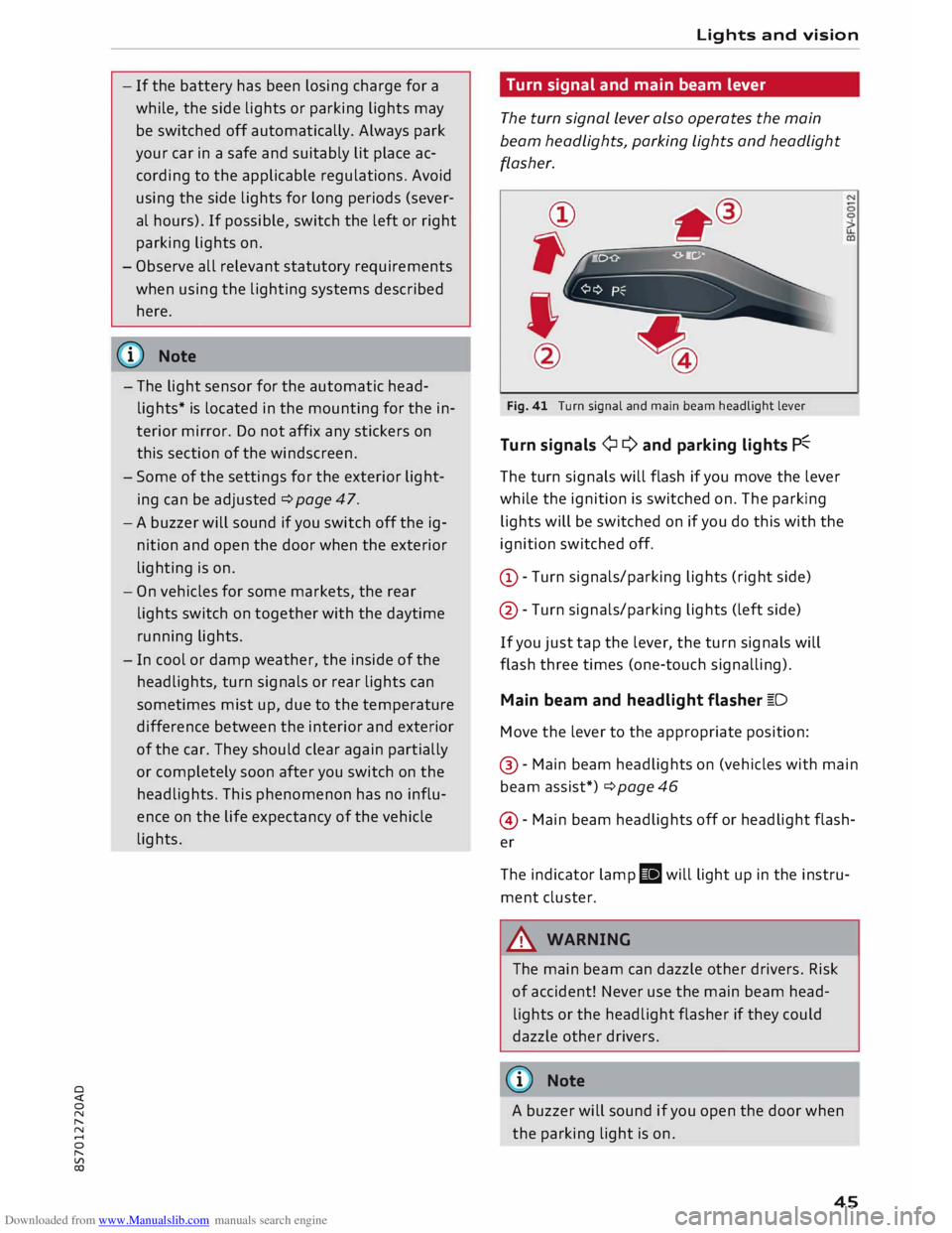
Fig. 41 Turn signal and main beam headlight lever
Turn signals ¢ Q and parking lights P�
The turn signals will flash if you move the lever
while the ignition is switched on. The parking
lights will be switched on if you do this with the
ignition switched off.
(D -Turn signals/parking lights (right side)
@ -Turn signals/parking lights (left side)
If you just tap the lever, the turn signals will
flash three times (one-touch signalling).
Main beam and headlight flasher �D
Move the lever to the appropriate position:
@ -Main beam headlights on (vehicles with main
beam assist*) ¢ page 46
@ -Main beam headlights off or headlight flash
er
The indicator lamp II will light up in the instru
ment cluster.
A WARNING
The main beam can dazzle other drivers. Risk
of accident! Never use the main beam head
lights or the headlight flasher if they could
dazzle other drivers.
(© Note
A buzzer will sound if you open the door when
the parking light is on .
45
Page 48 of 306
Downloaded from www.Manualslib.com manuals search engine Lights
and vision
Main beam assist
Applies to: vehicles with main beam assist
The main beam assist automatically switches
the main beam headlights on or off depending
on the surrounding light conditions.
A sensor (Located in the mounting for the interior
mirror) detects light sources from other road
users. The main beams are activated or deactiva
ted automatically depending on the position of
vehicles on either side of the road, on the road
speed, and on other traffic and ambient condi
tions.
On vehicles with matrix LED headlights, individu
al segments of the main beam are activated or
deactivated. The relevant sector in front of the
vehicle is masked, while the surrounding areas
remain lit. The ambient surroundings are thus il
luminated optimally without dazzling other road
users.
Activating the main beam assist
Important: The light switch must be set to AUTO,
the dipped beam headlights must be on and the
main beam assist must be activated on the info
tainment system¢ page 47.
... Press the lever forwards ®¢ page 45, Fig. 41
to activate the main beam assist. The indicator
lamp� will light up in the infotainment dis
play and the main beams will be switched on/
off automatically. An indicator lamp. lights
up when the main beams are switched on.
Switching the main beams on/off manually
If the main beams are not switched on or if the
headlights are not dipped as expected, you can
control the dip function manually:
.., To switch on the main beams manually, push
the lever to position @. The indicator lamp.
will light up .
... To dip the headlights manually, pull the lever
towards you@. The main beam assist will be
deactivated.
Flashing the headlights
... Pull the lever towards you© to flash the head
lights when the main beam assist is activated
46 and
the main beams are dipped. The main
beam assist will remain activated.
Driver messages on the infotainment display
Main beam assist: fault. See owner's manual
Drive to a qualified workshop soon and have the
fault rectified. You can still switch the main
beam headlights on and off manually.
Main beam assist: currently unavailable. Cam
era view restricted due to surroundings. See
owner's manual
The camera vision is impaired, e.g. by stickers or
dirt.
The sensor is located between the interior mirror
and the windscreen. Do not affix any stickers on
this section of the windscreen.
A WARNING
The main beam assist is only intended to as
sist the driver. The driver must always ensure
that the headlights are used when required,
and may have to switch them on or off man
ually, e.g. when the light conditions or visibili
ty are poor. In the following situations man
ual intervention may be necessary:
- Hazardous weather conditions such as fog,
heavy rain and snow or water splashes
- Roads on which oncoming traffic is partially
concealed (e.g. on motorways)
- Indiscernible road users (e.g. cyclists with
insufficient lighting or vehicles with dirty
rear lights)
- Tight corners, steep hill crests or valleys
- Poorly lit towns
- Highly reflective objects, such as road signs
- Windscreen misted up, dirty, frosted or cov-
ered by stickers in front of the sensor
(CD) Note
The main beam assist is deactivated whenever
you intervene by switching the main beams
on or off manually @.
Page 49 of 306
Downloaded from www.Manualslib.com manuals search engine 0
N
,.....
N Adjusting
the settings for the exterior
lighting
You can change the settings for these functions
on the infotainment system .
.., Select the following on the infotainment sys
tem: I MENU
I button >Car> left control button
> Vehicle settings > Exterior lighting.
Automatic headlights
The following settings are available in the Auto
matic headlights menu:
Activation time -You can determine how soon
the lights are switched on by using the settings
early, medium or late to adjust the sensitivity of
the light sensor.
Main beam assist* -You can switch the main
beam assist* on and off.
Audi adaptive light* -You can switch the adap
tive light on and off.
Headlight dip settings for driving at home
and abroad
If you drive a rig ht-hand drive vehicle in a left
hand drive country, or vice versa, it is not neces
sary to adjust the headlights, as they are de
signed for use when driving on the left or right.
Entry/exit lights
The entry lights illuminate the area around the
vehicle after dark when the vehicle is unlocked.
To activate this function, select Entry/exit lights.
The exit lights illuminate the area around the ve
hicle after dark when the ignition has been
switched off and the driver's door opened. To ac
tivate this function, select Entry/exit lights.
The entry and exit lights are operational after
dark when the light switch is set to AUTO.
8 l} This function is not available on all models or export ver
,.....
� sions. Lights
and vision
Hazard warning lights
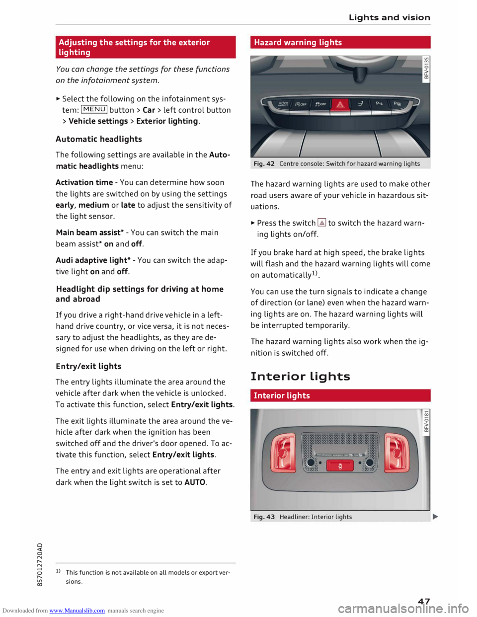
Fig. 42 Centre console: Switch for hazard warning lights
The hazard warning lights are used to make other
road users aware of your vehicle in hazardous sit
uations.
.., Press the switch � to switch the hazard warn-
ing lights on/off.
If you brake hard at high speed, the brake lights
will flash and the hazard warning lights will come
on automatically 1
).
You can use the turn signals to indicate a change
of direction (or lane) even when the hazard warn
ing lights are on. The hazard warning lights will
be interrupted temporarily.
The hazard warning lights also work when the ig
nition is switched off.
Interior Lights
Interior lights
Fig. 43 Headliner: Interior lights
47
Page 50 of 306
![AUDI TT ROADSTER 2016 Owners Manual Downloaded from www.Manualslib.com manuals search engine Lights
and vision
[i]- Courtesy light position. The interior lights are
switched on and off automatically when this
function is acti AUDI TT ROADSTER 2016 Owners Manual Downloaded from www.Manualslib.com manuals search engine Lights
and vision
[i]- Courtesy light position. The interior lights are
switched on and off automatically when this
function is acti](/img/6/57670/w960_57670-49.png)
Downloaded from www.Manualslib.com manuals search engine Lights
and vision
[i]- Courtesy light position. The interior lights are
switched on and off automatically when this
function is activated.
It is no longer necessary to operate a switch to
turn on the reading lights. Simply swipe or tap
your finger on the light to switch it on or off. The
light can be dimmed by keeping your finger in
contact with the reading light after switching it
on.
Interior lights
Various optional lighting functions are available
for the vehicle interior. The settings for certain
functions can be adjusted on the infotainment
system. Select the following on the infotainment
system: I MENU I button > Car > left control but
ton > Vehicle settings> Background lighting.
Instrument lighting
Fig. 44 Instrument lighting
The brightness of the lighting in the instrument
cluster and the centre console can be adjusted as
required.
.,. Briefly press the knob to release it.
.,. Turn the knob towards "-" or"+" to reduce or in
crease the brightness of the lighting.
.,. Briefly press the knob again to engage it.
48 Clear
vision
Adjusting the exterior mirrors
Fig. 45 Driver's door: Adjuster knob for exterior mirrors
Turn the knob to the appropriate position:
Q/P - To adjust the exterior mirror (left or right
side). Move the knob in the desired direction.
(fill - To heat the mirrors (depends on the outside
temperature).
8 - To fold in the exterior mirrors*. One of the
infotainment settings allows you to control
whether or not the mirrors are folded in when
you lock the vehicle �page 31.
Tilt function for exterior mirror on passenger
side*
The mirror is tilted slightly to provide a better
view of the kerb when parking backwards. This
feature only works when the knob is in the posi
tion for adjusting the mirror on the passenger
side.
You can adjust the tilted mirror surface by mov
ing the knob in the desired direction. This new
position is automatically stored and assigned to
the remote control key when you take the car out
of reverse .
The mirror returns to its original position as soon
as you drive forwards at over 15 km/h or switch
off the ignition.
A WARNING
Convex or wide-angle* exterior mirrors give a
larger field of vision. However, they make ob-
jects look smaller and further away than they
�
Page 51 of 306
Downloaded from www.Manualslib.com manuals search engine 0
N
,.....
N
......
0
,.....
Vl
CX) really
are. If you use these mirrors to esti
mate the distance to vehicles behind you
when changing lane, you could misjudge the
distance. Risk of accident!
CD CAUTION
If one of the mirror housings is knocked out
of position (e.g. when parking), the mirrors
must first be fully retracted with the electric
control. Do not readjust the mirror housing by
hand, as this will interfere with the mirror ad
juster function.
(!J) Note
If the electrical adjustment should fail to op
erate, both of the mirrors can be adjusted by
hand by lightly pressing the edge of the mir
ror glass.
Anti-dazzle setting
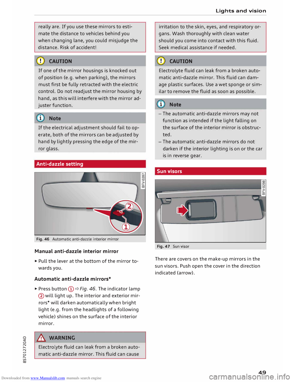
Fig. 46 Automatic anti-dazzle interior mirror
Manual anti-dazzle interior mirror
... Pull the lever at the bottom of the mirror to
wards you.
Automatic anti-dazzle mirrors*
.., Press button (D ¢ Fig. 46. The indicator lamp
@ will light up. The interior and exterior mir
rors* will darken automatically when bright
light (e.g. from the headlights of a following
vehicle) shines on the surface of the interior
mirror.
8_ WARNING
Electrolyte fluid can leak from a broken auto
matic anti-dazzle mirror. This fluid can cause Lights
and vision
irritation to the skin, eyes, and respiratory or
gans. Wash thoroughly with clean water
should you come into contact with this fluid.
Seek medical assistance if needed.
CD CAUTION
Electrolyte fluid can leak from a broken auto
matic anti-dazzle mirror. This fluid can dam
age plastic surfaces. Use a wet sponge or sim
ilar to remove the fluid as soon as possible.
@ Note
- The automatic anti-dazzle mirrors may not
function as intended if the light falling on
the surface of the interior mirror is obstruc
ted.
- The automatic anti-dazzle mirrors do not
darken if the interior lighting is on or the car
is in reverse gear.
Sun visors
Fig. 47 Sun visor
There are covers on the make-up mirrors in the
sun visors. Push open the cover in the direction
indicated (arrow).
49
Page 54 of 306
Downloaded from www.Manualslib.com manuals search engine Lights
and vision
Digital compass
Activating and deactivating the compass
Applies to: vehicles with digital compass
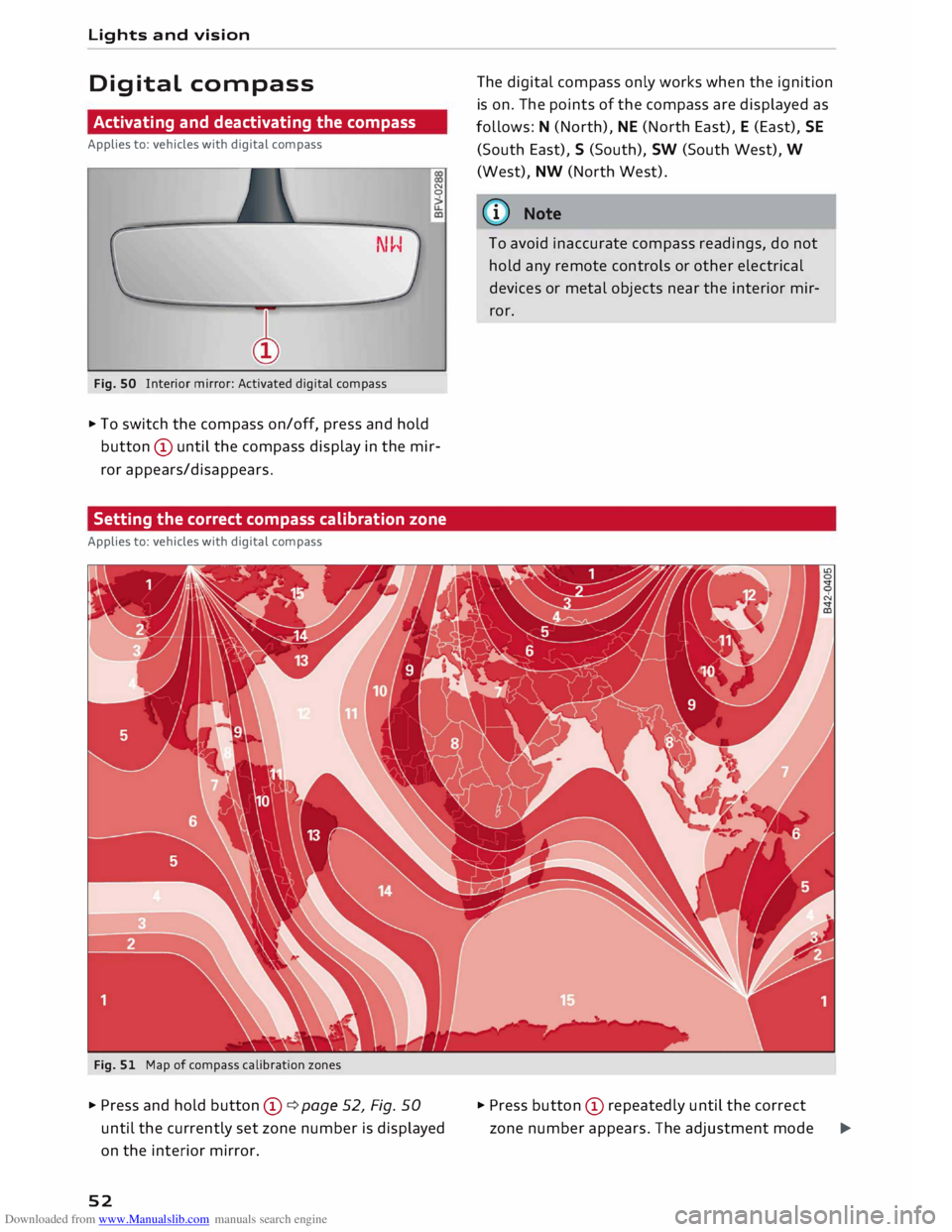
Fig. SO Interior mirror: Activated digital compass N
0
.,. To switch the compass on/off, press and hold
button © until the compass display in the mir
ror appears/disappears.
Setting the correct compass calibration zone
Applies to: vehicles with digital compass
Fig. 51 Map of compass calibration zones
.,. Press and hold button ©¢ page 52, Fig. 50
until the currently set zone number is displayed
on the interior mirror.
52 The
digital compass only works when the ignition
is on. The points of the compass are displayed as
follows: N (North), NE (North East), E (East), SE
(South East), S (South), SW (South West), W
(West), NW (North West).
ij)) Note
To avoid inaccurate compass readings, do not
hold any remote controls or other electrical
devices or metal objects near the interior mir
ror.
.,. Press button © repeatedly until the correct
zone number appears. The adjustment mode
�
Page 55 of 306
Downloaded from www.Manualslib.com manuals search engine 0
N
,.....
N
......
0
,.....
Vl
CX) will
be ended automatically after a few sec
onds.
Calibrating compass
Applies to: vehicles with digital compass
The compass must be re-calibrated if the display
is incorrect or inaccurate .
... Press and hold button (D until the letter Cap
pears on the interior mirror .
... Drive in a circle at a speed of about 10 km/h un
til a point of the compass is displayed on the in
terior mirror.
& WARNING
- Calibrate your compass at a location where
there is no traffic so that you do not endan
ger yourself or other road users (accident
risk).
- Always pay attention to the road and the
area surrounding the vehicle when you are
reading the compass while the vehicle is
moving. Lights
and vision
53
Page 64 of 306
Downloaded from www.Manualslib.com manuals search engine Heating
and cooling
Controls for automatic air conditioner
Applies to: vehicles with automatic air conditioner
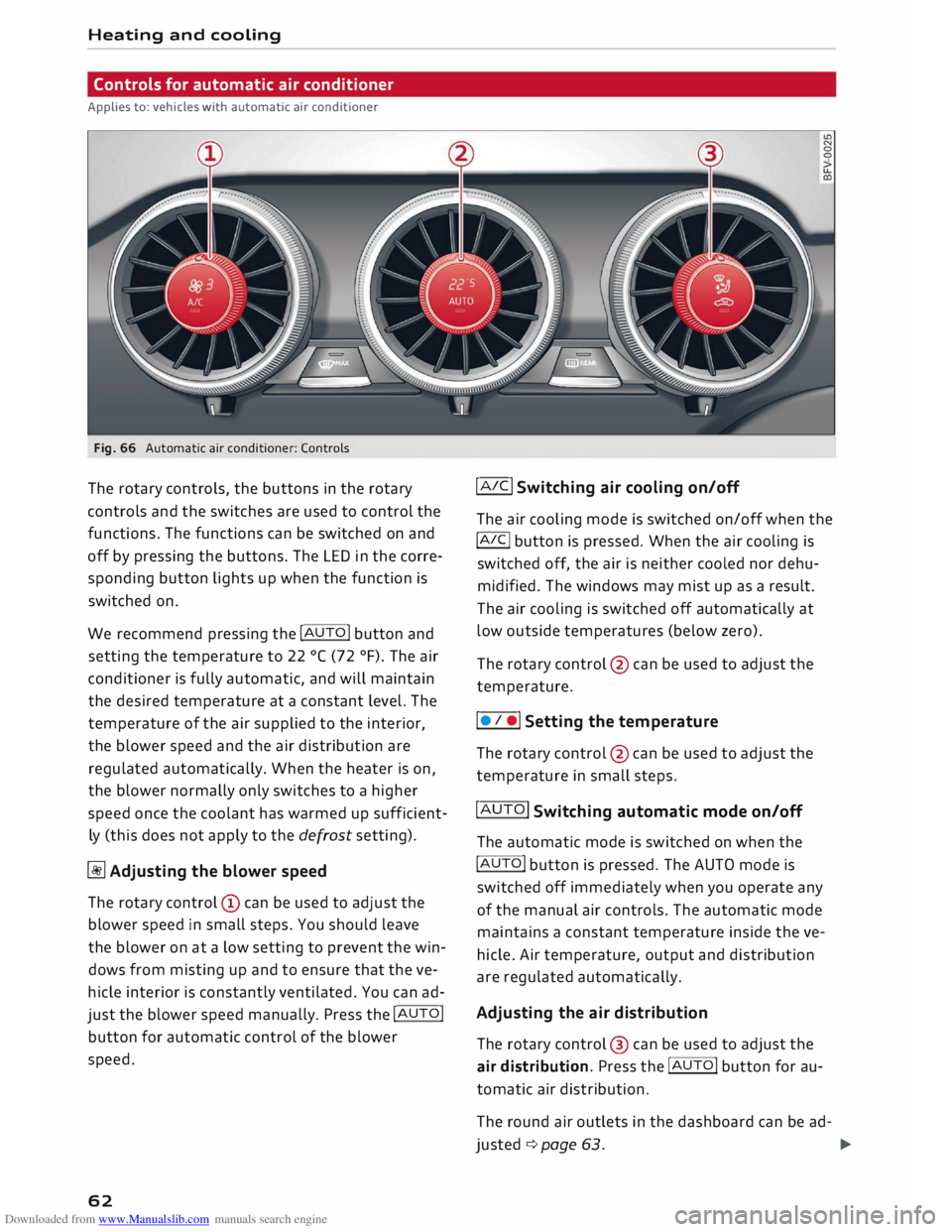
Fig. 66 Automatic air conditioner: Controls
The rotary controls, the buttons in the rotary
controls and the switches are used to control the
functions. The functions can be switched on and
off by pressing the buttons. The LED in the corre
sponding button lights up when the function is
switched on.
We recommend pressing the !AUTO! button and
setting the temperature to 22 °( (72 °F). The air
conditioner is fully automatic, and will maintain
the desired temperature at a constant level. The
temperature of the air supplied to the interior,
the blower speed and the air distribution are
regulated automatically. When the heater is on,
the blower normally only switches to a higher
speed once the coolant has warmed up sufficient
ly (this does not apply to the defrost setting).
� Adjusting the blower speed
The rotary control @ can be used to adjust the
blower speed in small steps. You should leave
the blower on at a low setting to prevent the win
dows from misting up and to ensure that the ve
hicle interior is constantly ventilated. You can ad
just the blower speed manually. Press the !AUTO!
button for automatic control of the blower
speed.
62 !AIC!
Switching air cooling on/off
The air cooling mode is switched on/off when the
!A IC!
button is pressed. When the air cooling is
switched off, the air is neither cooled nor dehu
midified. The windows may mist up as a result.
The air cooling is switched off automatically at
low outside temperatures (below zero).
The rotary control @ can be used to adjust the
temperature.
I • I •I Setting the temperature
The rotary control @ can be used to adjust the
temperature in small steps.
!AUTO! Switching automatic mode on/off
The automatic mode is switched on when the
!AUTO! button is pressed. The AUTO mode is
switched off immediately when you operate any
of the manual air controls. The automatic mode
maintains a constant temperature inside the ve
hicle. Air temperature, output and distribution
are regulated automatically.
Adjusting the air distribution
The rotary control @ can be used to adjust the
air distribution. Press the !AUTO! button for au
tomatic air distribution.
The round air outlets in the dashboard can be ad-
justed ¢ page 63.
�