charging AUDI TT ROADSTER 2018 Owners Manual
[x] Cancel search | Manufacturer: AUDI, Model Year: 2018, Model line: TT ROADSTER, Model: AUDI TT ROADSTER 2018Pages: 310, PDF Size: 46.95 MB
Page 41 of 310
Cl co .... N ,..._
N .... 0 ,..._
Vl co
turned on in accordance with traffic
reg ulations.
- If the battery has been discharging for a
while, the parking light may sw itch off auto­
matically. A lways make sure your vehicle is
parked and adequately lit according to the
laws . Avo id using the parking lights for sev­
era l hours.
- Always observe legal reg ulat ions when us­
ing the light ing systems described.
(!') Tips
- The light sensor for the automatic head ­
lights* is in the rearview mirror mount. Do
not place any stickers in this area on the
windsh ield.
- Some exterior lighting fu nctions can be ad­
j usted
c::> page 39.
- If you turn off the ignition wh ile the exterio r
lights are on and open the door, a warning
tone so unds.
- In some markets, the ta il lights will sw itch
on when the dayt ime runn ing lights sw itch
on.
- In cool o r damp weather, the inside of the
headlig hts, tu rn s ignals and tai l lights can
fog over d ue to the tem perature d ifference
betwee n the inside and ou ts ide. They will
clea r shor tly after sw itch ing them o n. This
d oes not aff ect t he serv ice life o f the lig ht­
i ng.
Turn signal and high beam lever
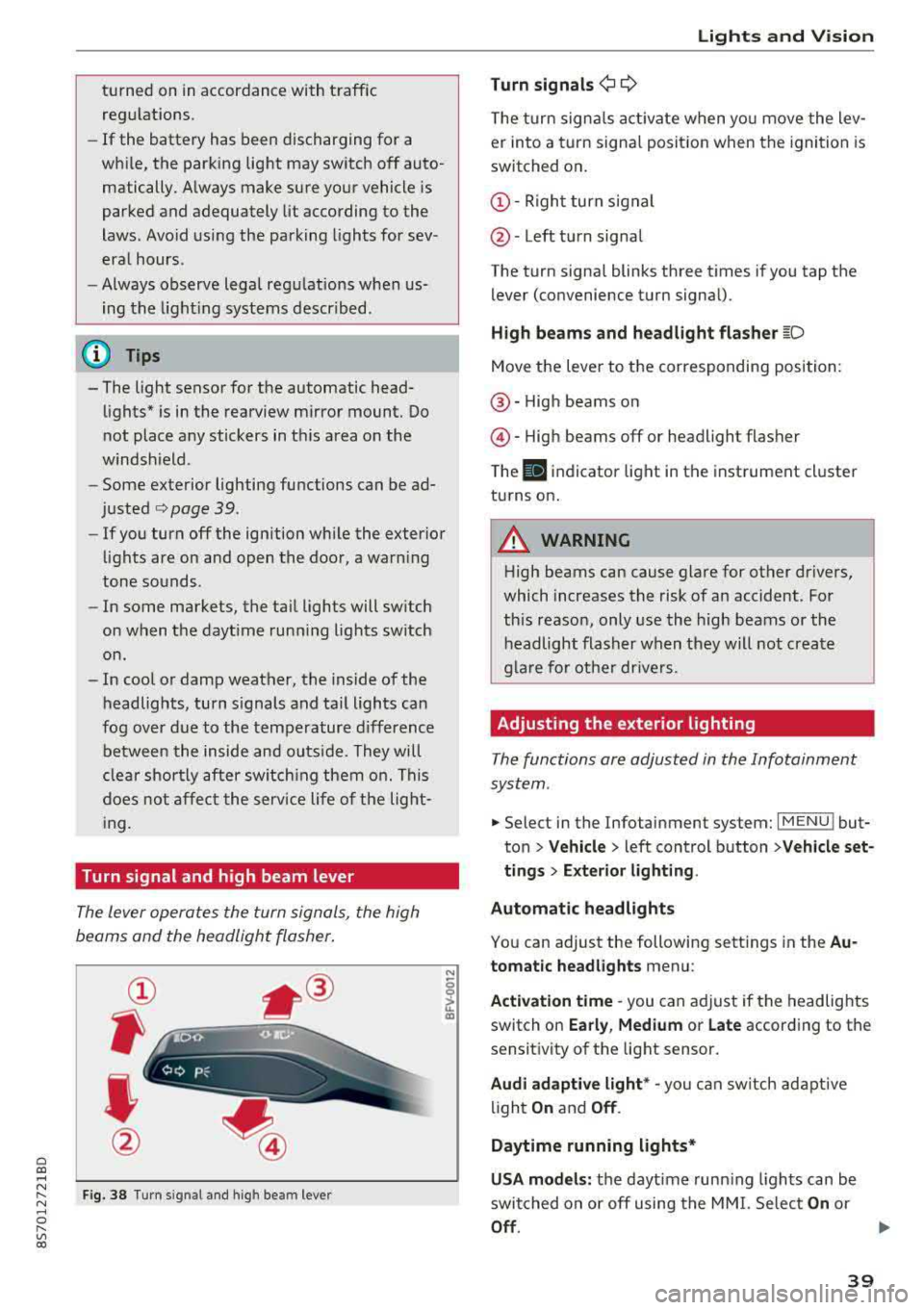
The lever opera tes the turn sign als, the high
beams and the headlight flasher .
Fig . 38 Tu rn signal an d high beam lever
N
0
~
"'
Lights and V ision
Turn signals ¬Ę 9
The turn signa ls act ivate w hen yo u move the lev­
er into a turn signa l posit io n when the igni tion is
switched on .
©-Righ t turn signal
@ -Left tur n signal
The turn signa l blinks three t imes i f you tap t he
lever (convenience t urn signa l).
High beams and headlight flasher
~D
Move t he lever to the corresponding position:
@ -High beams o n
@-High beams off or headlight flasher
T he
II indicato r light in t he inst rument cl uster
turns on .
A WARNING
-High beams can cause glare for other drivers,
which increases the risk of an accident. Fo r
this reaso n, only use the high beams or the
headlight flasher when they wil l not create
g la re fo r ot her dr ivers.
Adjusting the exterior lighting
The functions are adjusted in the Infotainment
system .
.,. Select in the Infotainment system: I MENU ! but­
ton> Vehicle > left control button >Vehicle set­
tings > Exterior lighting .
Automatic headlights
You can adjust the following sett ings in the Au­
tomatic headlights menu:
Activation time
-you can a djust if the headlights
switch on Early, Medium or Late according to the
sensit ivity of the light sensor.
Audi adaptive light * -you can sw itch ad ap tive
li gh t
On and Off .
Daytime running lights*
USA models: the daytime runn ing ligh ts can be
switched on or off using the MM I. Se lec t
On or
Off .
39
Page 61 of 310
Cl 00 .-< N r--­N .-< 0 r--­Vl 00
-Never turn off the engine before the vehicle
has come to a complete stop.
- The brake booster and power steering only
work when the engine is running. If the en­ gine is off, you have to use more force when
steering or braking. Because you cannot
steer and brake as you usually would, this
could lead to accidents and serious injuries.
@ Note
Avoid high engine speed, full throttle, and
heavy engine load if the engine has not
reached operating temperature yet. You could
damage the engine.
@ For the sake of the environment
Do not let the engine run while parked to
warm up. Begin driving immediately . This re­
duces unnecessary emissions.
(D Tips
-Some noise after starting the engine is nor­
mal and is no cause for concern.
- If you leave the vehicle with the ignition
switched on, the ignition will switch off af­
ter a certain amount of time. Make sure that
electrical equipment such as the exterior
lights are switched off.
Stopping the engine
.,. Bring the vehicle to a full stop.
.,. Move the selector lever into the P position .
... Press the I START ENGINE STOPI button.
Emergency off function*
If it is absolutely necessary, the engine can also
be turned off while driving at speeds starting at
4 mph (7 km/h). To switch the engine off, press
the
I START ENGINE STOPI button twice in a row
br iefly or press and hold for longer than two sec­
onds.
A WARNING
- Never turn off the engine before the vehicle has come to a complete stop.
Driving
-Please note that the brake booster and pow­
er steering only work when the engine is
running. When the engine off, you must use
more force to steer or brake the vehicle. Be­
cause the usual steering and braking capa­
bility is not available, the risk of accidents or
. . . . mJunes increases.
-For safety reasons, always park the vehicle
with the selector lever in the P position.
Otherwise, there is the risk that the vehicle
could roll.
- After the engine has been switched off, the
radiator fan can continue to run for up to 10
minutes
-even with the ignition switched
off. It can also switch on again after some
time if the coolant temperature rises as the result of heat buildup or if the engine is al­
ready warm and the engine compartment is
also heated by the sun's rays.
@ Note
If the engine has been under heavy load for
an extended period of time, heat builds up in
the engine compartment after the
engine is
switched off and there is a risk of damaging
the engine . For this reason, let the engine run
at idle for approximately two minutes before
shutting it off.
(D Tips
For up to 10 minutes after stopping the en­
gine, the radiator fan may turn on again auto­ matically or it may continue to run (even if
the ignition is switched off) for the following
reasons :
- The coolant temperature is increasing due
to trapped heat.
- If the engine is warm and the engine com­
partment also heats up from strong sun­
light.
Messages
Turn off ignition before leaving vehicle. Battery
is discharging
This message appears and a warning tone sounds
if you open the driver's door when the ignition is
..,
59
Page 162 of 310
Media
CD Note
Always follow the information found in ~CD in
Wi-Fi hotspot on page 130.
@ Tips
- Depending on the Internet connection and
network traffic, a connection loss can occur
d uring p layback of on line media services.
- Onli ne med ia and Inte rn et r adi o usage de­
pends on the service availability of the third
party provider .
- Audi AG simply makes the access to online
media services possible through the MMI
and does not take any respons ibility for the
contents of the online media services.
- Always read the chapter ¬Ę
page 131, About
Audi connect .
-Depending on the mobile device used, there
may be interruptions during media playback
and when using the
Au di MM I connect app.
To avoid interruptions when using a mobile
device, do not lock the screen on your mo ­
bile device and keep the
A udi MMI c onn ect
app in the foreground.
- Contact an authorized Audi dea ler or au­
thorized Audi Service Facility for additional
i nformat io n about on line media.
160
Multimedia connections
USB adapter for Audi music interface or
USB charging port
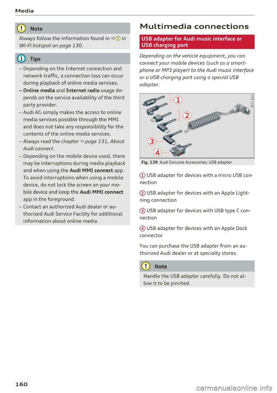
Depending on the vehicle equipment, you can
connect your mobile devices (such as a smart­
phone or MP3 player) to the Audi music interface
or a USB charging port using a special USB
adapter.
"'
I
Fig. 139 A ud i Ge nuin e Acce sso ries : USB a dapter
@ USB adapter for devices with a micro USB con ­
nect ion
@ USB adapter for devices with an Apple Light­
ning connection
@ USB adapter for dev ices with USB type C con ­
nection
@ USB adapter for devices with an Apple Dock
connector
You can purchase the USB adapter from an au ­
thorized Audi dea ler or at specialty sto res.
CD Note
Hand le the USB adapter carefully . Do not al­
l ow it to be pinched.
Page 163 of 310
Cl co ..... N ,....
N ..... 0 ,....
Vl co
Audi music interface
Applies to: ve hicles with Audi m usic in terface
Connect your mobile devices to the Audi music
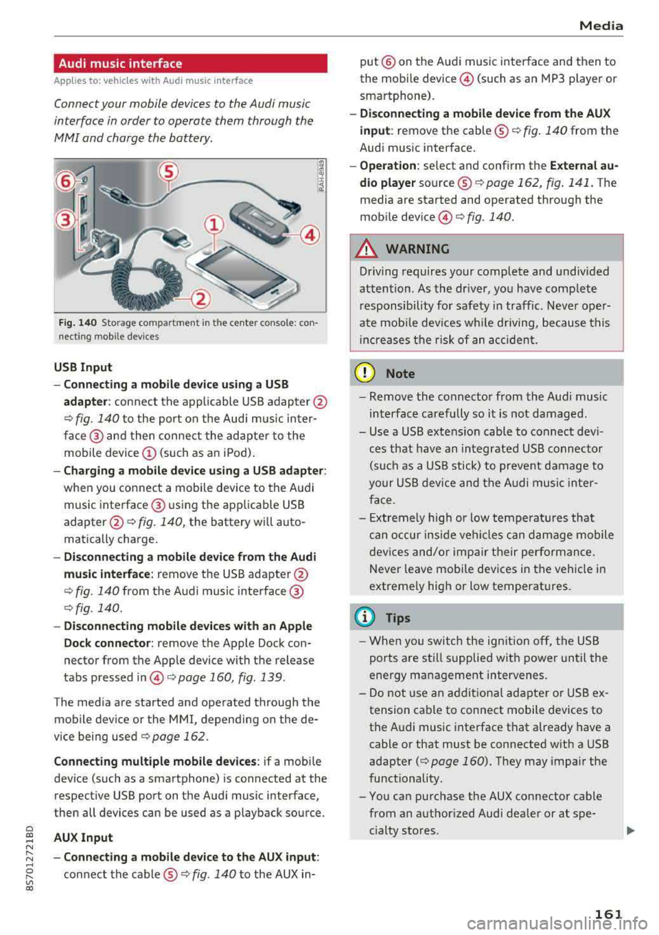
interface in order to operate them through the
MMI and charge the battery.
'" ‚ÄĘ.I 'I'
1 .
Fig. 140 S torage co mpa rtment in the ce nte r conso le: co n­
nect ing m ob ile dev ices
USB Input
- Connecting a mobile device using a
USB
adapter : connect the applicable USB adap ter @
¬Ę fig. 140 to the port on the Audi music inter¬≠
face @ and then connect the adapter to the
mobile device
(D (such as an iPod).
-Charging a mobile device using a USB adapter :
when you connect a mobile device to the Audi
music interface @ using the app licab le USB
adapter @¬Ę fig. 140, the battery will auto¬≠
matically charge .
-Disconnecting a mobile device from the Audi
music interface :
remove the USB adapter @
¬Ę fig. 140 from the Audi music interface @
¬Ęfig . 140.
-Disconnecting mobile devices with an Apple
Dock connector:
remove the Apple Dock con­
nector from the Apple device with the release
tabs pressed
in @ ¬Ępage 160, fig .139 .
The media are started and operated through the
mobile device or the MMI , depending on the de­
vice being used
¬Ępage 162 .
Connecting multiple mobile devices: if a mobile
device (such as a smartphone) is connected at the respect ive USB port on the Audi music interface,
then all devices can be used as a playback source .
AUX Input
-Connecting a mobile device to the AUX input:
connect the cable¬ģ¬Ę fig. 140 to the AUX in-
Media
put @ on the Audi music interface and then to
the mobile
device @ (such as an MP3 player or
smartphone).
- Disconnecting a mobile device from the AUX
input :
remove the cable ¬ģ¬Ę fig. 140 from the
Audi music interface.
- Operation : select and confirm the External au­
dio player
source ¬ģ¬Ę page 162, fig . 141. The
media are started and operated through the
mob ile
device @) ¬Ęfig. 140.
A WARNING
-
Driving requires your complete and undivided
attention . As the driver, you have complete
responsibility for safety in traffic. Never oper­
ate mobile devices wh ile d riving, because this
i nc reases the risk of an accident.
(D Note
-Remove the connector from the Audi music
interface carefully so it is not damaged.
- Use a USB extens ion cable to connect devi­
ces that have an integrated USB connector
(such as a USB stick) to prevent damage to
your USB device and the Audi music inter­
face .
- E xtremely high or low temperatures that
can occur inside vehi cles can damage mobile
devices and/or impair their performance.
Never leave mobi le dev ices in the vehicle in
extreme ly high or low temperat ures.
@ Tips
- When you switch the ignitio n off, the USB
ports are still supplied with power until the
energy management intervenes.
- Do not u se an additional adapter or USB ex­
tension cable to connect mobile devices to
the Audi music interface that already have a
cable or that must be connected with a USB
adapter
( ¬Ę page 160). They may impair the
functionality.
- You can purchase the AUX connector cable from an authorized Audi dealer or at spe­
cialty stores .
161
Page 244 of 310
Checking and Filling
A WARNING
California Proposit ion 65 Warning:
- Battery posts, terminals and related acces­ sories contain lead and lead compounds, chemicals known to the State of California
to cause cancer and reproductive problems .
Wash hands after handling .
Q) Note
If the vehicle will be parked for long periods
of t ime, protect it against the cold so that it
w ill not be destroyed by "freezing"
~page 242 .
Vehicle battery
The term "vehicle battery " refers to the 12 Volt
battery in your vehicle .
Not running the vehicle for long p eriods of
t ime
If you do not drive your vehicle for several days or
weeks, electrical equipment is gradually scaled
back or switched off . This reduces energy use and
ensures the veh icle w il l be able to sta rt after long
pe riods of time
i:::> page 91. Some convenience
functions, such as interior light ing or power sea t
adjustment, may not be available under certain
circumstances . These convenience functions will
be avai lab le again once you switch the ignition on
and start the engine.
Even when electrical equipment is switched off ,
the equipment can still drain the vehicle battery if the vehicle is not driven for long periods of
time. Deep draining results in a chemical reaction
that destroys the inside of the vehicle battery.
The vehicle battery must be charged every month to reduce the risk of this happen ing
i:::> page 242.
Contact an author ized Audi dealer or authorized
Aud i Serv ice Facility for more information.
Winter operati on
Cold weather places higher demands on the vehi­
cle battery . This results in reduced start ing abili ­
ty . Have the vehicle battery checked by an au­
thori zed Audi dealer or authorized Audi Service
Facility before the co ld time of year.
242
Charging the vehicle battery
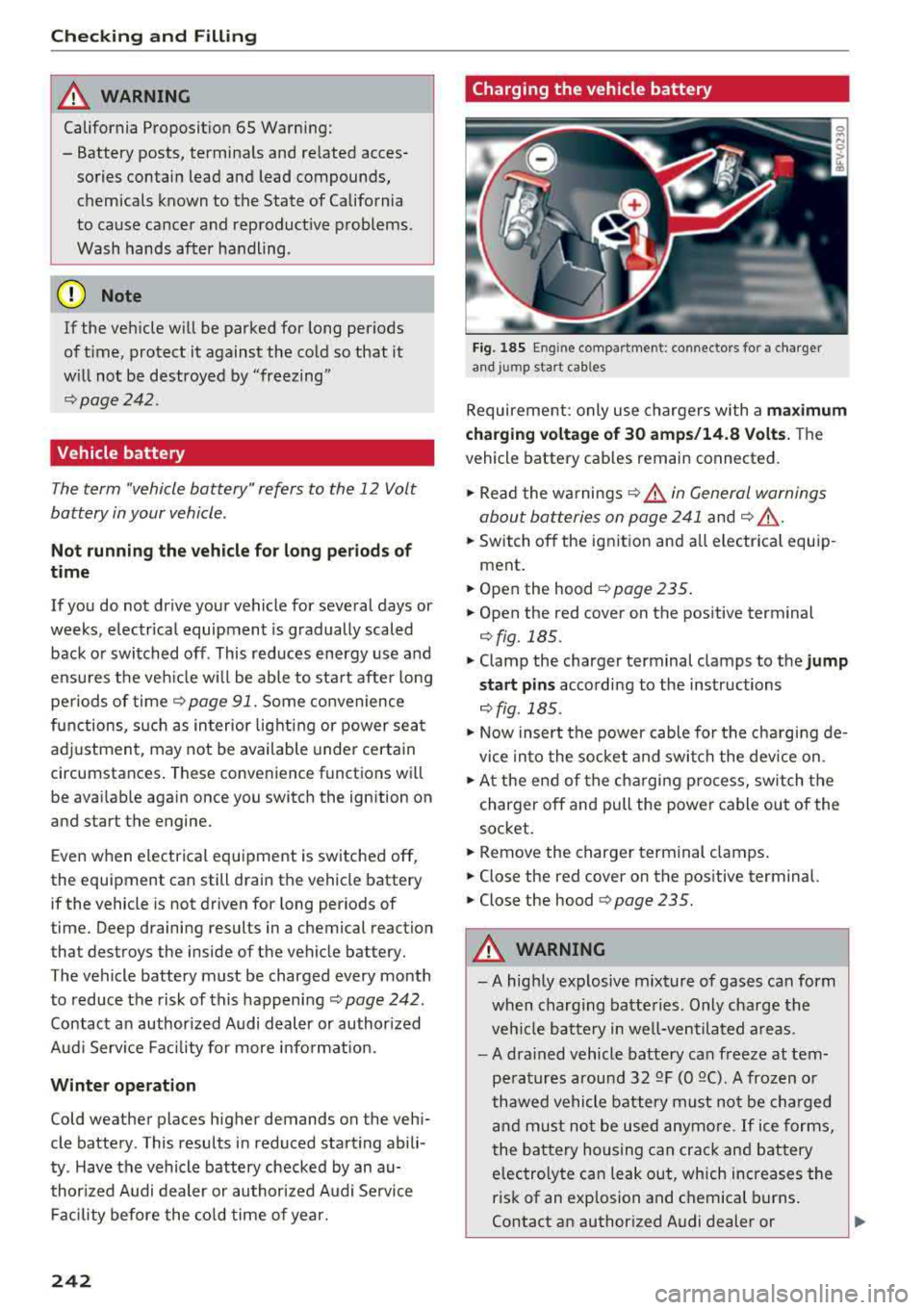
Fig. 18 5 En g in e compartmen t: co nn ectors fo r a cha rger
a n d jum p start cab les
Requireme nt: only use chargers with a maximum
charging volt age of 30 amp s/14.8 Volts.
The
vehicle battery cables remain connected.
... Read the wa rnings i:::> ,& in General warnings
about batteries on page 241
and i:::> ,& .
... Switch off the ignition and all electrica l equip ­
ment .
... Open the hood i:::> page 235 .
... Open the red cover on the positive terminal
¬Ęfig. 185.
... Clamp the charger terminal clamps to the jump
s ta rt pins
according to the instructions
c::> fig . 185 .
... Now insert the power cable for the cha rging de­
vice into the socket and switch the device on .
... At the end of the charging process, switch the
charger off and pull the power cable out of the
socket .
... Remove the charger terminal clamps.
... Close the red cover on the pos itive terminal.
... Close the hood i:::> page 235.
A WARNING
-A highly explosive m ixture of gases can form
when charg ing batteries . Only charge the
veh icle battery in well-ventilated areas.
-A drained vehicle battery can freeze at tem­
peratures around 32
QF (0 QC) . A frozen or
thawed vehicle battery must not be charged
and must not be used anymore. If ice forms,
the battery housing can crack and battery
electrolyte can leak out, which increases the
risk of an explosion and c hemical burns .
Contact an authorized Audi dealer or
..,_
Page 245 of 310
Cl 00 .-< N r-­N .-< 0 r-­Vl 00
authorized Audi Service Facility for more in­
formation.
- Do not connect or disconnect the charging
cable while charging because this increases
the risk of an exp losion.
(D Tips
- Only charge the vehicle battery through the
connections in the engine compartment.
- Read all of the manufacturer's instructions
for the charger before charging the vehicle
battery.
Windshield washer system
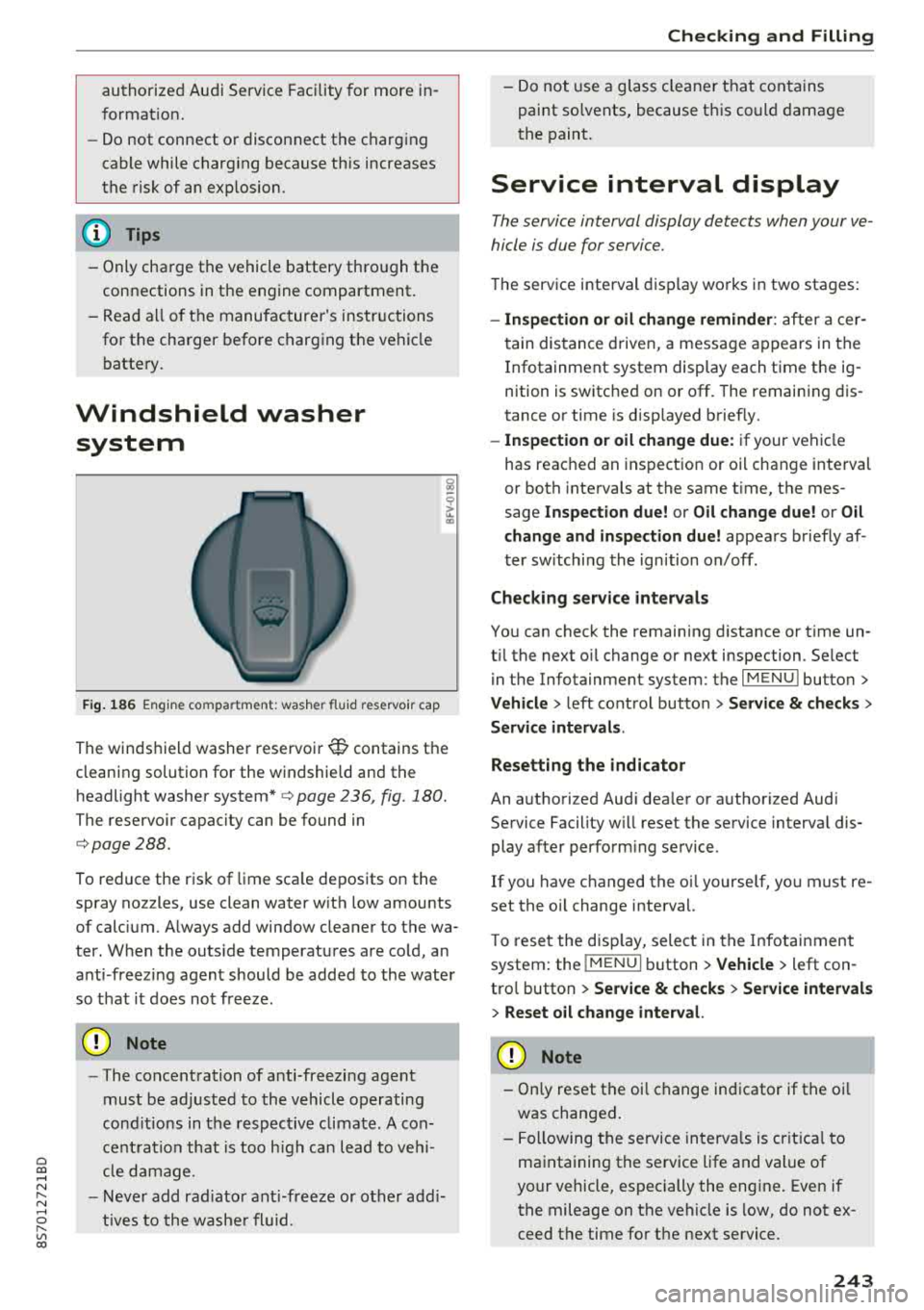
Fig. 186 Engine compa rtment: washer flu id reservo ir cap
The windshield washer reservoir W contains the
cleaning solution for the windshie ld and the
headlight washer
system* ¬Ę page 236, fig . 180.
The reservoir capacity can be found in
¬Ępage 288.
To reduce the risk of lime sca le deposits on the
spray nozzles, use clean water with low amounts
of calc ium. A lways add window cleaner to the wa­
ter. When the outs ide temperatures are cold, an
anti -freezing agent should be added to the water
so that it does not freeze.
@ Note
-The concentration of anti-freezing agent
must be adjusted to the vehicle operating
cond itions in the respective climate. A con­
ce ntrat ion that is too high can lead to vehi­
cl e damage.
- Never add radiator anti-freeze or other addi­
tives to the washer fluid.
Checking and Filling
- Do not use a glass cleaner that contains
paint so lvents, because t his could damage
the paint.
Service interval display
The service interval display detects when your ve ­
hicle is due for service .
The service interval display works in two stages:
-Inspection or oil change reminder : after a cer-
tain distance driven, a message appears in the
In fotainment system display each time the ig ­
nition is switched on or off. The remaining dis­
tance or time is disp layed briefly.
- Inspection or oil change due: if your vehicle
has reached an inspection or oil change interval
or both intervals at the same t ime, the mes­
sage
Inspection due! or Oil change due! or Oil
change and inspection due!
appears briefly af ­
ter switching the ignition on/off .
Checking service intervals
You can check the remaining distance or time un ­
t il the next oil change or next inspection. Se lect
in the Infotainment system: the
I MENU I button>
Vehicle > left control button > Service & checks >
Service intervals .
Resetting the indicator
An authorized Audi dea ler or authorized Audi
Service Facility w ill reset the service interval dis­
play after performing service.
If you have ch anged the oi l yourse lf, you must re ­
set the oil change interval.
T o reset the disp lay, select in the Infotainment
system: the
I MENUI button> Vehicle> left con­
trol button >
Service & checks > Service intervals
> Reset oil change interval.
@ Note
-Only reset the oil change indicator if the oi l
was changed.
- Following the service intervals is crit ica l to
maintaining the service life and value of
your vehicle, especially the engi ne. Even if
the mileage on the vehicle is low, do not ex­
ceed the time for the next service.
243
Page 286 of 310
Emergency situations
@ Tips
The discharged battery must be properly con·
nected to the vehicle's electrical system .
When jump starting or charging the battery,
never connect the negative ground cable to
the battery negative post because the battery
manager system must be able to detect the
battery's state of charge. Always connect the
negat ive g round cable to the negative ground
post of the battery manager control unit.
Using the jump start
cable
Both jump start cables must be connected in the
correct order!
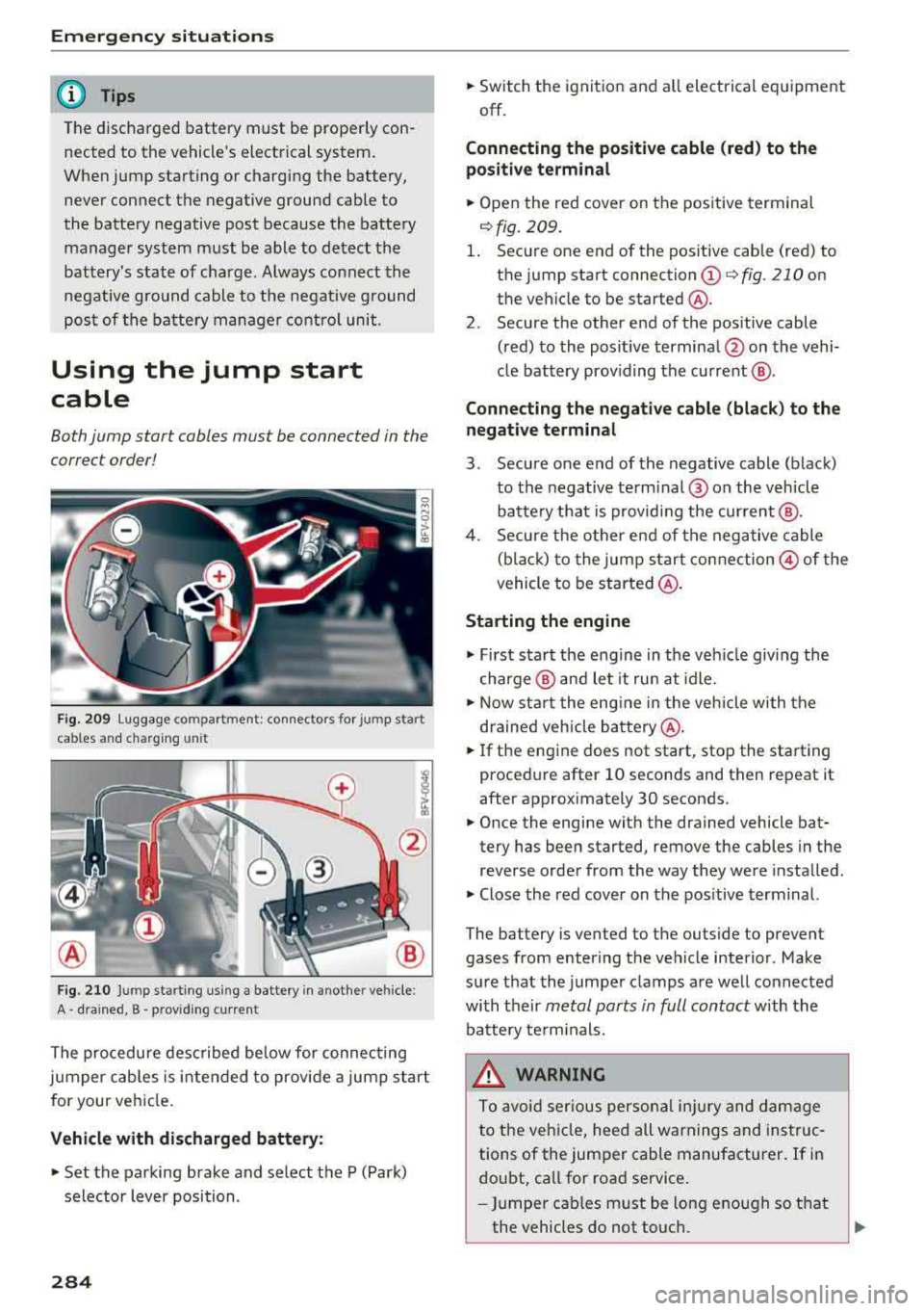
Fig. 209 luggage compartme nt: connectors for jump start
cables and charg ing unit
Fig. 210 Jump starting usi ng a battery in anot her vehicle:
A¬∑ drained, B ‚ÄĘ provid ing curren t
The procedure described below for connecting
jumper cables is intended to provide a jump start
for your vehicle.
Vehicle with discharged battery:
.. Set the parking brake and select the P (Park)
selector lever position.
284
.. Switch the ignition and all electrical equipment
off.
Connecting the positive cable (red) to the
positive terminal
.. Open the red cover on the positive terminal
<=:>fig. 209.
1. Secure one end of the positive cable (red) to
the ju mp start connection
(D c:> fig. 210 on
the vehicle to be started @.
2 . Secure the other end of the pos itive cable
(red) to the positive terminal @on the vehi·
cle battery prov iding the current @.
Connecting the negative cable (black ) to the
negative terminal
3 . Secure one end of the negative cable (black)
to the negative term inal @ on the vehicle
batte ry that is providing the current @.
4. Secure the other end of the negative cable
(black) to the jump start connection
@of the
vehicle to be started @.
Starting the engine
.,. First start the engine in the vehicle giving the
charge @ and let it run at idle .
.. Now start the engine in the vehicle with the
drained veh icle battery @.
.. If the engine does not start, stop the starting
procedure after 10 seconds and then repeat it
after approximately 30 seconds .
.. Once the engine with the drained vehicle bat·
tery has been started, remove the cables in the
reverse order from the way they were installed .
.. Close the red cover on the pos itive terminal.
The battery is vented to the outside to prevent
gases from enter ing the vehicle interior. Make
sure that the jumper clamps are well connected
with their
metal ports in full contact with the
battery termin als.
.&_ WARNING
To avoid serious personal injury and damage
to the vehicle, heed all warnings and instruc­
tions of the jumper cable manufacturer. If in
doubt, call for road service .
- Jumper cables must be long enough so that
the vehicles do not touch.
Page 307 of 310
Temperature indicator
Coolant . . . . . . . . . . . . . . . . . . . . . . . . . . . . . . 8
Text messages . . . . . . . . . . . . . . . . . . . . . . . 116
also refer to Text messages . . . . . . . . . . . 116
T ie-downs . . . . . . . . . . . . . . . . . . . . . . . . . . . 184
Tightening specification (wheel bo lts) . . . . 2 78
T ime . . . . . . . . . . . . . . . . . . . . . . . . . . . . . . . 173
tiptron ic (automatic transmission) . . . . . . . . 67
T ire Mob ility System ( tire repair set) . . . . . . 273
T ires ...... .. .. ................ ... .. . 244
A ll wheel dr ive . . . . . . . . . . . . . . . . . . . . . . . 89
L ow-profile tires . . . . . . . . . . . . . . . . . . . . . 259
R epair se t . . . . . . . . . . . . . . . . . . . . . . 27 2, 273
Rep lac ing . . . . . . . . . . . . . . . . . . . . . . . . . . 2 7 5
Service life . . . . . . . . . . . . . . . . . . . . . . . . . 253
Tire press ure . . . . . . . . . . . . . . . . . . . . . . . 254
Tire pr ess ure monitoring system . . . 26 1, 262
Tire press ure table . . . . . . . . . . . . . . . . . . . 255
Treadwear indicators . . . . . . . . . . . . . . . . . 253
Un id irectional . . . . . . . . . . . . . . . . . . . 246 , 278
Uniform t ire quality grad ing . . . . . . . . . . . 260
Tires and w heels
Glossary of tire and load ing termino logy . 246
Tire s and vehicle load limit s . . . . . . . . . . . 256
TMC
refer to Tr affic information . . . . . . . . . . . . 14 7
Tone (sound)
refer to Adjusting the sou nd . . . . . . . . . . . 177
Tool . . . . . . . . . . . . . . . . . . . . . . . . . . . . . . . . 272
To uch
refer to MMI touch . . . . . . . . . . . . . . . . . . . 95
Towing Tow t rucks . . . . . . . . . . . . . . . . . . . . . . . . . 285
T PMS (tire p ressure monitoring system) . . . 261
Indicator light . . . . . . . . . . . . . . . . . . . . . . 265
T ire press ure mon itor ing system . . . . . . . 262
T raffic info rmation ............ 145, 146, 147
T raff ic reports . . . . . . . . . . . . . . . . . . . . . . . . 143
T ransmission malfunction (indicator light) . . 68
T ransport Canada . . . . . . . . . . . . . . . . . . . . . 185
T rave l guide
refer to Tr avel (travel g uide) . . . . . . . . . . . 127
T rave l (t rave l guide) . . . . . . . . . . . . . . . . . . . 127
~ Treb le (so und) . . . . . . . . . . . . . . . . . . . . . . . 17 7
.-<
~ Trunk lid
N 8 Tr un k es cape la tch . . . . . . . . . . . . . . . . . . . 272
r--­Vl 00
Index
Turn signals . . . . . . . . . . . . . . . . . . . . . . . . . . 39
u
Un fastening safety bel ts
Un iform tire qua lity grading ........... .
U nlocking/loc king 192
260
By r emot e control . . . . . . . . . . . . . . . . . . . . 24
U sing the door lock cy linder . . . . . . . . . . . . 27
With the centra l loc king switch . . . . . . . . . 26
With the conven ience key . . . . . . . . . . . . . . 25
U pdating stations (radio) . . . . . . . . . . . . . . . 149
U 5B stick
refer to Au di m usic in terface . . . . . . . 160, 161
U sing the jump start cable . . . . . . . . . . . . . . 284
V
Vanity mirror . . . . . . . . . . . . . . . . . . . . . . . . . . 42
Vehicle Care/cleaning . . . . . . . . . . . . . . . . . . . . . . . 266
Dimensions . . . . . . . . . . . . . . . . . . . . . . . . . 288
Out of service . . . . . . . . . . . . . . . . . . . . . . . 2 71
Raising . . . . . . . . . . . . . . . . . . . . . . . . . . . . 276
Spec ificat ions . . . . . . . . . . . . . . . . . . . . . . . 288
Vehicle battery . . . . . . . . . . . . . . . . . . . . . . . 241
Charge leve l . . . . . . . . . . . . . . . . . . . . . . . . . 91
Charging . . . . . . . . . . . . . . . . . . . . . . . . 12, 242
I ndicato r light . . . . . . . . . . . . . . . . . . . . . . . 12
Winter operat ion . . . . . . . . . . . . . . . . . . . . 242
also refer to Battery . . . . . . . . . . . . . . . . . 241
Vehicle care . . . . . . . . . . . . . . . . . . . . . . . . . . 266
Vehicle jack . . . . . . . . . . . . . . . . . . . . . . 272, 279
Li ft ing po ints . . . . . . . . . . . . . . . . . . . . . . . 276
Vehicle tool kit . . . . . . . . . . . . . . . . . . . . . . . 272
Version information . . . . . . . . . . . . . . . . . . . 176
VIEW ....... ... .. .. ................ .. 20
VI EW button . . . . . . . . . . . . . . . . . . . . . . . . . . 18
VIN . . . . . . . . . . . . . . . . . . . . . . . . . . . . . . . . 288
Vo ice gu idance . . . . . . . . . . . . . . . . . . . . . . . 141
also refer to Mult ifunct ion
stee ring wheel ... .. ............ 18, 19, 20
Vo icemail . . . . . . . . . . . . . . . . . . . . . . . . . . . 118
Vo ice recog nit ion sys tem . . . . . . . . . . . . 19, 105
C ommands . . . . . . . . . . . . . . . . . . . . . . . . . 106
Externa l . . . . . . . . . . . . . . . . . . . . . . . . . . . 110
Settings . . . . . . . . . . . . . . . . . . . . . . . . . . . 173
Vo lume . . . . . . . . . . . . . . . . . . . . . . . . . . . . 178
305