corner BMW 1 SERIES 2013 E82 Owner's Manual
[x] Cancel search | Manufacturer: BMW, Model Year: 2013, Model line: 1 SERIES, Model: BMW 1 SERIES 2013 E82Pages: 288, PDF Size: 6.73 MB
Page 81 of 288
76
ControlsControls overview
Tachometer
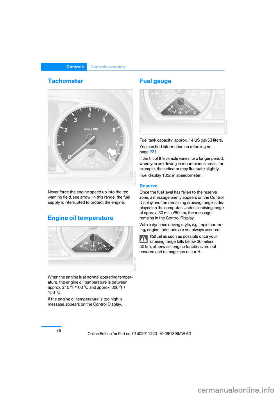
Never force the engine speed up into the red
warning field, see arrow. In this range, the fuel
supply is interrupted to protect the engine.
Engine oil temperature
When the engine is at normal operating temper-
ature, the engine oil temperature is between
approx. 2107/100 6 and approx. 300 7/
150 6.
If the engine oil temp erature is too high, a
message appears on the Control Display.
Fuel gauge
Fuel tank capacity: approx. 14 US gal/53 liters.
You can find information on refueling on
page 221.
If the tilt of the vehicle varies for a longer period,
when you are driving in mountainous areas, for
example, the indicator may fluctuate slightly.
Fuel display 135i: in speedometer.
Reserve
Once the fuel level ha s fallen to the reserve
zone, a message briefly appears on the Control
Display and the remaining cruising range is dis-
played on the computer. Under a cruising range
of approx. 30 miles/50 km, the message
remains in the Control Display.
With a dynamic driving style, e.g. rapid corner-
ing, engine functions are not always assured.
Refuel as soon as possible once your
cruising range falls below 30 miles/
50 km; otherwise, engine functions are not
ensured and damage can occur. <
00320051004F004C00510048000300280047004C0057004C005200510003
Page 93 of 288
88
ControlsTechnology for driving comfort and safety
Technology for driving comfort and safety
Vehicle equipment
In this chapter, all pr oduction, country, and
optional equipment that is offered in the model
range is described. For this reason, descrip-
tions will be given of some equipment that may
not be available in a vehi cle, for example due to
the special options or national-market version
selected. This also app lies to safety related
functions and systems.
Park Distance Control PDC
The concept
The PDC assists you with maneuvering in tight
parking spaces. Acoustic signals and a visual
indicator warn you of the presence of an object
behind your vehicle. Four ultrasonic sensors in
the bumper measure the distance.
These sensors have a range of approx. 6.5 ft/
2 m. However, an acoustic warning does not
sound until an object is approx. 24 in/60 cm
from the corner sensors or approx. 5 ft/1.50 m
from the center sensors.
PDC is a parking aid that can indicate
objects when they are approached
slowly, as is usually th e case when parking.
Avoid approaching an object at high speed; oth-
erwise, physical circumstances may lead to the
system warning being issued too late. <
Switching on automatically
With the engine running or the ignition switched
on, the system is activated after approx. second
when you engage reverse gear or move the
automatic transmission selector lever to
position R. Wait this short period before driving.
Switching off automatically
After approx. 164 ft/50 m of driving or above
approx. 18 mph/30 km/h, the system switches
off and the LED goes out.
Signal tones
When nearing an object, its position is indicated
correspondingly by an in terval tone. As the dis-
tance between vehicle an d object decreases,
the intervals betwee n the tones become
shorter. If the distance to the nearest object
falls to below roughly 1 ft/30 cm, then a contin-
uous tone sounds.
An interval tone is interrupted after approx.
3seconds:
> If you stop in front of an object that has been
detected by only one of the corner sensors
> If you are driving parallel to a wall
Malfunction
The warning lamp lights up. A mes-
sage appears on the Control Display.
PDC is malfunctioning. Have the
system checked.
To avoid this problem, keep the sensors clean
and free of ice or snow in order to ensure that
they will continue to op erate effectively. When
using a high-pressure cleaner, do not spray the
sensors for extended periods of time and only
from a distance of at least 1 ft/30 cm.
PDC with visual warning
The approach of the vehicle to an object is
shown on the Control Display. Objects that are
farther away are displayed on the Control Dis-
play before a signal tone sounds. The display
appears on the Control Display as soon as PDC
is activated.
00320051004F004C00510048000300280047004C0057004C005200510003
Page 107 of 288
102
ControlsLamps
angle and other parameters, the light from the
headlamp follows the course of the road.
In tight curves such as on switchbacks or when
turning, at speeds up to approx. 40 mph/
70 km/h, an additional, cornering light is
switched on that lights up the area inside the
curve.
Activating Adaptive Light Control
With the ignition switched on, turn the light
switch to position 3, refer to page 100.
The corner-illuminating lamp is switched on
automatically, depending on the steering wheel
angle or turn signal indicator.
Standstill function: to avoid blinding oncoming
traffic, the Adaptive Light Control does not
direct light toward the driver's side when the
vehicle is at a standstill.
When you are reversing, only the corner-illumi-
nating lamps are switched on and active on
both sides.
Malfunction
The warning lamp lights up. A mes-
sage appears on the Control Display.
The Adaptive Light Control is mal-
functioning or failed. Ha ve the system checked
as soon as possible.
High beams/roadside parking
lamps
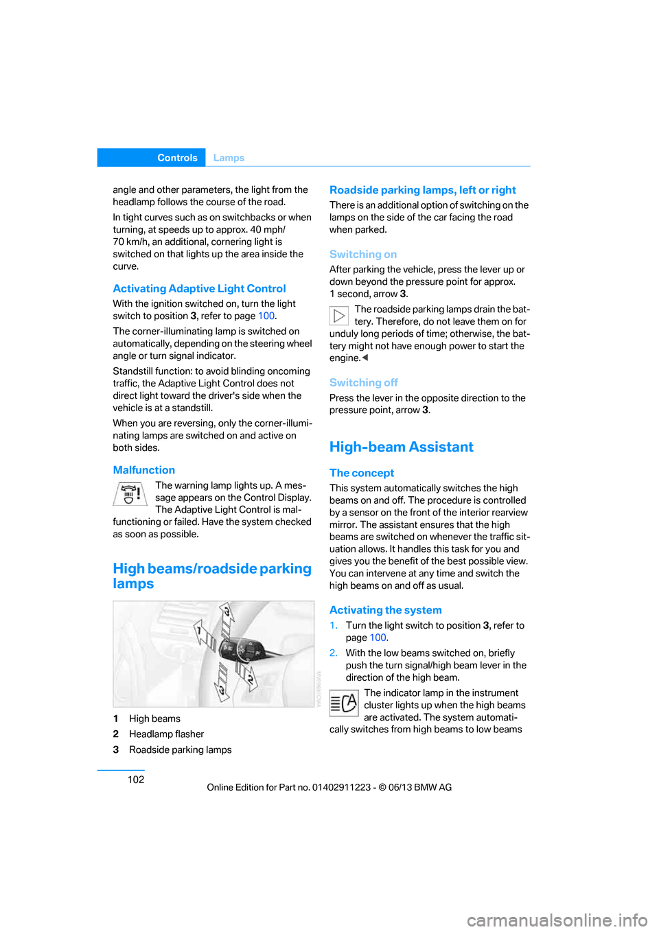
1 High beams
2 Headlamp flasher
3 Roadside parking lamps
Roadside parking lamps, left or right
There is an additional option of switching on the
lamps on the side of the car facing the road
when parked.
Switching on
After parking the vehicle, press the lever up or
down beyond the pressu re point for approx.
1 second, arrow 3.
The roadside parking lamps drain the bat-
tery. Therefore, do not leave them on for
unduly long periods of time; otherwise, the bat-
tery might not have enou gh power to start the
engine. <
Switching off
Press the lever in the o pposite direction to the
pressure point, arrow 3.
High-beam Assistant
The concept
This system automatically switches the high
beams on and off. The procedure is controlled
by a sensor on the front of the interior rearview
mirror. The assistant ensures that the high
beams are switched on whenever the traffic sit-
uation allows. It handle s this task for you and
gives you the benefit of the best possible view.
You can intervene at any time and switch the
high beams on and off as usual.
Activating the system
1. Turn the light switch to position 3, refer to
page 100.
2. With the low beams switched on, briefly
push the turn signal/high beam lever in the
direction of the high beam.
The indicator lamp in the instrument
cluster lights up when the high beams
are activated. The system automati-
cally switches from hi gh beams to low beams
00320051004F004C00510048000300280047004C0057004C005200510003
Page 133 of 288
128
Driving tipsThings to remember when driving
1,400 lbs and there will be five 150-lb
passengers in your vehicle, the amount of
available cargo and lugga ge load capacity is
650 lbs:
1,400 lbs minus 750 lbs = 650 lbs.
5. Determine the combined weight of luggage
and cargo being loaded on the vehicle. That
weight may not safely exceed the available
cargo and luggage load capacity calculated
in step 4.
6. If your vehicle will be towing a trailer, part of
the load from your tra iler will be transferred
to your vehicle. Co nsult the manual for
transporting a trailer to determine how this
may reduce the available cargo and luggage
load capacity of your vehicle.
Load
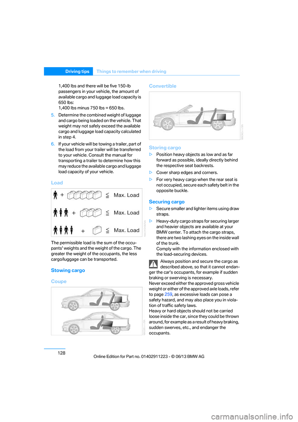
The permissible load is the sum of the occu-
pants' weights and the weight of the cargo. The
greater the weight of the occupants, the less
cargo/luggage can be transported.
Stowing cargo
Coupe Convertible
Storing cargo
>
Position heavy objects as low and as far
forward as possible, ideally directly behind
the respective seat backrests.
> Cover sharp edges and corners.
> For very heavy cargo when the rear seat is
not occupied, secure each safety belt in the
opposite buckle.
Securing cargo
> Secure smaller and lighter items using draw
straps.
> Heavy-duty cargo straps for securing larger
and heavier objects are available at your
BMW center. To attach the cargo straps,
there are two lashing eyes on the inside wall
of the trunk.
Comply with the information enclosed with
the load-securing devices.
Always position and secure the cargo as
described above, so that it cannot endan-
ger the car's occupants, for example if sudden
braking or swerving is necessary.
Never exceed either the approved gross vehicle
weight or either of the a pproved axle loads, refer
to page 259, as excessive loads can pose a
safety hazard, and may al so place you in viola-
tion of traffi c safety laws.
Heavy or hard objects should not be carried
loose inside the car, since they could be thrown
around, for example as a result of heavy braking,
sudden swerves, etc., and endanger the
occupants.
00320051004F004C00510048000300280047004C0057004C005200510003
Page 134 of 288
129
Things to remember when driving
Driving tips
Only attach the cargo st
raps using the lashing
eyes shown in the illust ration. Do not secure
cargo with the anchors for tether straps, refer to
page 60, otherwise, these could be damaged. <
Coupe: roof-mounted
luggage rack
A special rack system is available as an option
f o r y o u r B M W . C o m p l y w i t h t h e d i r e c t i o n s g i v e n
in the installation instructions.
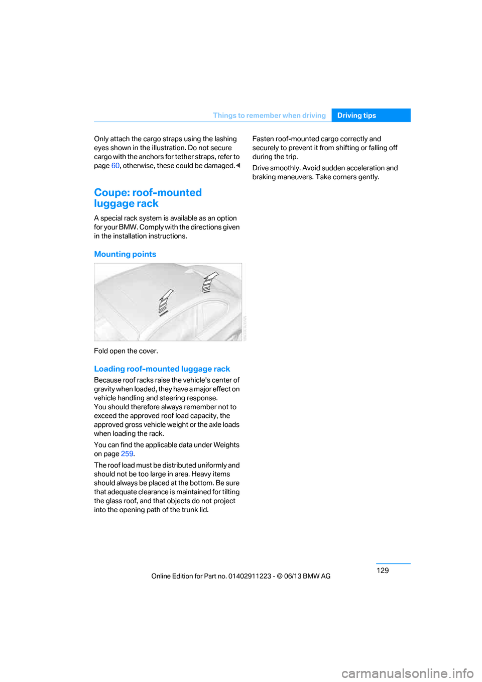
Mounting points
Fold open the cover.
Loading roof-mounted luggage rack
Because roof racks raise the vehicle's center of
gravity when loaded, they have a major effect on
vehicle handling and steering response.
You should therefore always remember not to
exceed the approved roof load capacity, the
approved gross vehicle weight or the axle loads
when loading the rack.
You can find the applicable data under Weights
on page 259.
The roof load must be distributed uniformly and
should not be too larg e in area. Heavy items
should always be placed at the bottom. Be sure
that adequate clearance is maintained for tilting
the glass roof, and that objects do not project
into the opening path of the trunk lid. Fasten roof-mounted cargo correctly and
securely to prevent it fr
om shifting or falling off
during the trip.
Drive smoothly. Avoid sudden acceleration and
braking maneuvers. Take corners gently.
00320051004F004C00510048000300280047004C0057004C005200510003
Page 234 of 288
229
Wheels and tires
Mobility
The traction grade assigned to this tire is
based on straight-ahe
ad braking traction
tests, and does not include acceleration,
cornering, hydroplaning, or peak traction
characteristics. <
Temperature
The temperature grades are A, the highest, B,
and C, representing the ti re's resistance to the
generation of heat and its ability to dissipate
heat when tested under controlled conditions
on a specified indoor laboratory test wheel.
Sustained high temperature can cause the
material of the tire to degenerate and reduce
tire life, and excessive temperature can lead to
sudden tire failure. The grade C corresponds to
a level of performance which all passenger car
tires must meet under the Federal Motor Vehi-
cle Safety Standard No. 109. Grades B and A
represent higher levels of performance on the
laboratory test whee l than the minimum
required by law.
The temperature grade for this tire is
established for a tire that is properly
inflated and not overloaded. Excessive speed,
underinflation, or exce ssive loading, either
separately or in combin ation, can cause heat
buildup and possible tire failure. <
RSC – run-flat tires
You will recognize run-flat tires by a circular
symbol containing the letters RSC on the side
of the tire, refer to page230.
M+S
Winter and all-season tires.
These have better wint er properties than
summer tires.
XL
Designation for specia lly reinforced tires.
Tire condition
Inspect your tires frequently for tread wear,
signs of damage and for foreign objects lodged
in the tread. Check the tread depth.
Minimum tread depth
The tread depth should not drop below 0.12 in/
3 mm, although, for example, European legisla-
tion only specifies a minimum tread depth of
0.063 in/1.6 mm. At tread depths below 0.12 in/
3 mm there is an increased risk of high-speed
hydroplaning, even when only small amounts of
water are present on the road surface.
When winter tires wear down past a tread depth
of 0.16 in/4 mm, they be come perceptibly less
suitable for winter condit ions. In the interest of
safety, new tires sh ould be installed.
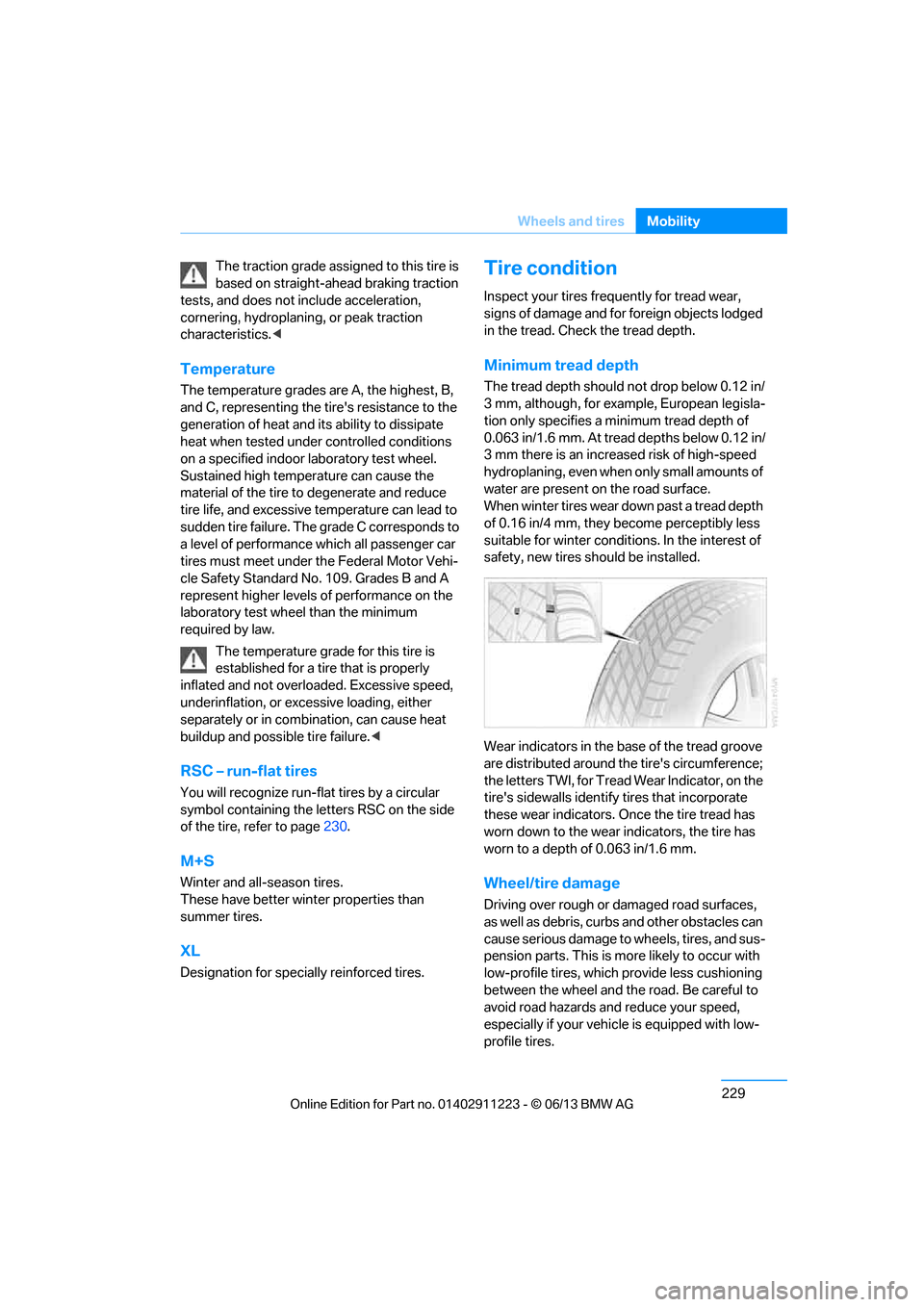
Wear indicators in the base of the tread groove
are distributed around th e tire's circumference;
the letters TWI, for Tread Wear Indicator, on the
tire's sidewalls identify tires that incorporate
these wear indicators. On ce the tire tread has
worn down to the wear indicators, the tire has
worn to a depth of 0.063 in/1.6 mm.
Wheel/tire damage
Driving over rough or damaged road surfaces,
as well as debris, curbs and other obstacles can
cause serious damage to wheels, tires, and sus-
pension parts. This is more likely to occur with
low-profile tires, which provide less cushioning
between the wheel and th e road. Be careful to
avoid road hazards and reduce your speed,
especially if your vehi cle is equipped with low-
profile tires.
00320051004F004C00510048000300280047004C0057004C005200510003
Page 250 of 288
245
Replacing components
Mobility
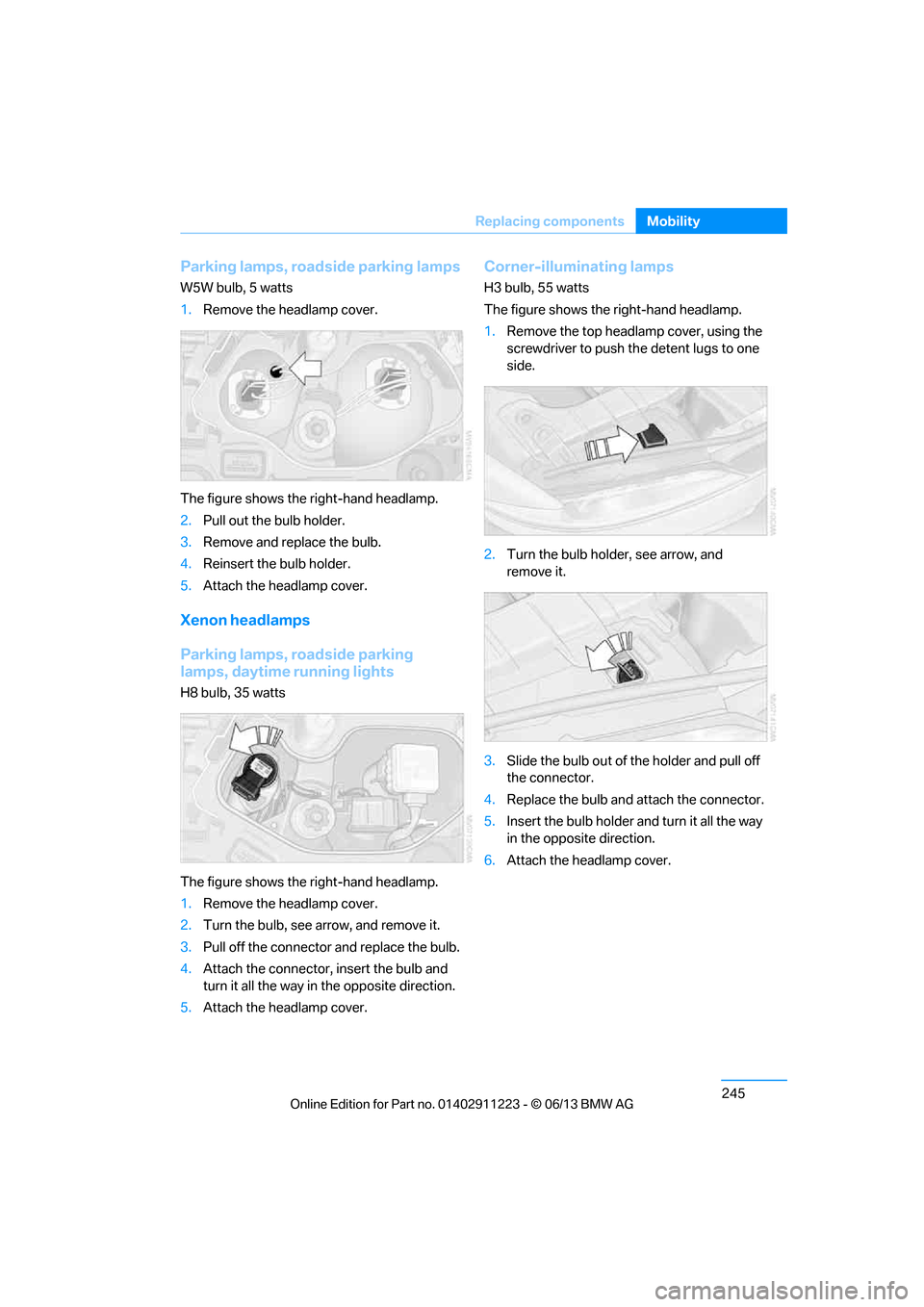
Parking lamps, roadside parking lamps
W5W bulb, 5 watts
1.
Remove the headlamp cover.
The figure shows the right-hand headlamp.
2. Pull out the bulb holder.
3. Remove and replace the bulb.
4. Reinsert the bulb holder.
5. Attach the headlamp cover.
Xenon headlamps
Parking lamps, roadside parking
lamps, daytime running lights
H8 bulb, 35 watts
The figure shows the right-hand headlamp.
1.Remove the headlamp cover.
2. Turn the bulb, see arrow, and remove it.
3. Pull off the connector and replace the bulb.
4. Attach the connector, insert the bulb and
turn it all the way in the opposite direction.
5. Attach the headlamp cover.
Corner-illuminating lamps
H3 bulb, 55 watts
The figure shows the right-hand headlamp.
1.Remove the top headlamp cover, using the
screwdriver to push th e detent lugs to one
side.
2. Turn the bulb holder, see arrow, and
remove it.
3. Slide the bulb out of the holder and pull off
the connector.
4. Replace the bulb and attach the connector.
5. Insert the bulb holder and turn it all the way
in the opposite direction.
6. Attach the headlamp cover.
00320051004F004C00510048000300280047004C0057004C005200510003
Page 258 of 288
253
Giving and receiving assistance
Mobility
Use only the tow fitting provided with the
vehicle and screw it a
ll the way in. Use the
tow fitting for towing on paved roads only. Avoid
lateral loading of the tow fitting, e.g. do not lift
the vehicle by the tow fitting. Otherwise, the
tow fitting and the vehicle could be damaged. <
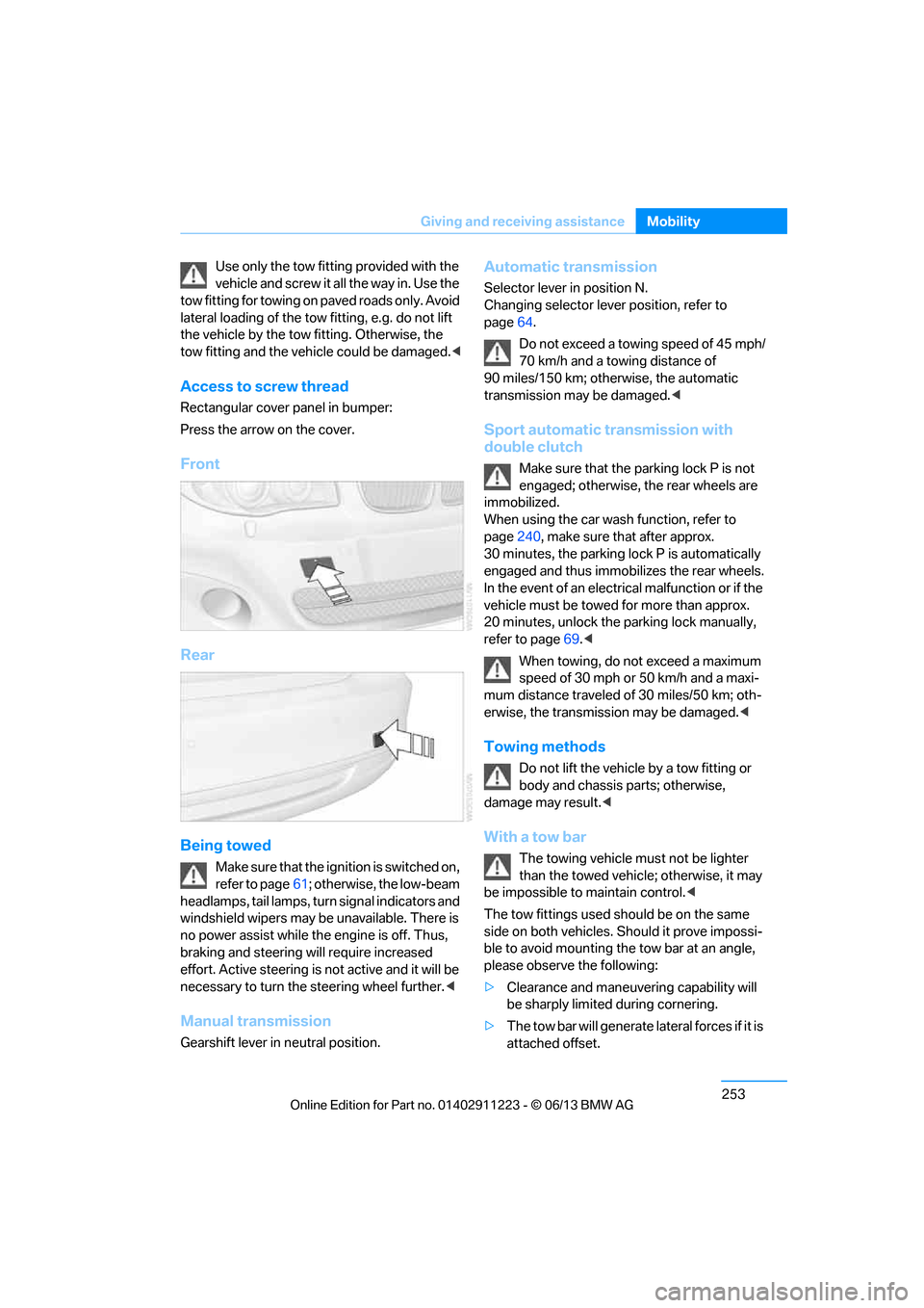
Access to screw thread
Rectangular cover panel in bumper:
Press the arrow on the cover.
Front
Rear
Being towed
Make sure that the ignition is switched on,
refer to page61; otherwise, the low-beam
headlamps, tail lamps, turn signal indicators and
windshield wipers may be unavailable. There is
no power assist while the engine is off. Thus,
braking and steering will require increased
effort. Active steering is not active and it will be
necessary to tu rn the steering wheel further. <
Manual transmission
Gearshift lever in neutral position.
Automatic transmission
Selector lever in position N.
Changing selector lever position, refer to
page 64.
Do not exceed a towing speed of 45 mph/
70 km/h and a towing distance of
90 miles/150 km; otherwise, the automatic
transmission may be damaged. <
Sport automatic transmission with
double clutch
Make sure that the parking lock P is not
engaged; otherwise, the rear wheels are
immobilized.
When using the car wash function, refer to
page 240, make sure that after approx.
30 minutes, the parking lock P is automatically
engaged and thus immobilizes the rear wheels.
In the event of an electrical malfunction or if the
vehicle must be towed for more than approx.
20 minutes, unlock the parking lock manually,
refer to page 69.<
When towing, do not exceed a maximum
speed of 30 mph or 50 km/h and a maxi-
mum distance traveled of 30 miles/50 km; oth-
erwise, the transmission may be damaged. <
Towing methods
Do not lift the vehicle by a tow fitting or
body and chassis parts; otherwise,
damage may result. <
With a tow bar
The towing vehicle must not be lighter
than the towed vehicle; otherwise, it may
be impossible to maintain control.<
The tow fittings used sh ould be on the same
side on both vehicles. Should it prove impossi-
ble to avoid mounting the tow bar at an angle,
please observe the following:
> Clearance and maneuvering capability will
be sharply limited during cornering.
> The tow bar will ge nerate lateral forces if it is
attached offset.
00320051004F004C00510048000300280047004C0057004C005200510003
Page 276 of 288
271
Everything from A to Z
Reference
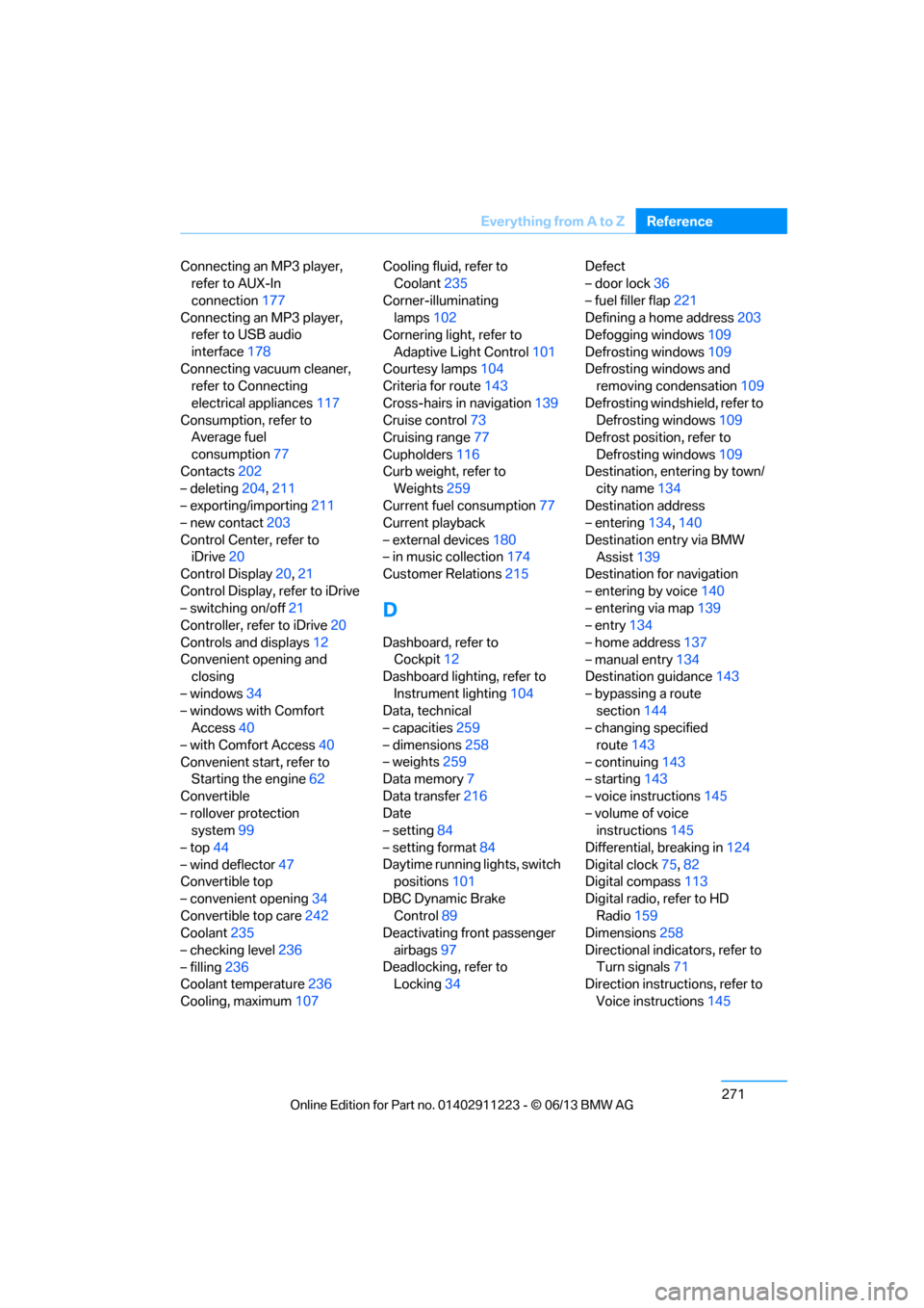
Connecting an MP3 player,
refer to AUX-In
connection 177
Connecting an MP3 player, refer to USB audio
interface 178
Connecting vacuum cleaner, refer to Connecting
electrical appliances 117
Consumption, refer to Average fuel
consumption 77
Contacts 202
– deleting 204,211
– exporting/importing 211
– new contact 203
Control Center, refer to iDrive 20
Control Display 20,21
Control Display, refer to iDrive
– switching on/off 21
Controller, refer to iDrive 20
Controls and displays 12
Convenient opening and closing
– windows 34
– windows with Comfort Access 40
– with Comfort Access 40
Convenient start, refer to Starting the engine 62
Convertible
– rollover protection system 99
– top 44
– wind deflector 47
Convertible top
– convenient opening 34
Convertible top care 242
Coolant 235
– checking level 236
– filling 236
Coolant temperature 236
Cooling, maximum 107Cooling fluid, refer to
Coolant 235
Corner-illuminating lamps 102
Cornering light, refer to
Adaptive Light Control 101
Courtesy lamps 104
Criteria for route 143
Cross-hairs in navigation139
Cruise control 73
Cruising range 77
Cupholders 116
Curb weight, refer to Weights 259
Current fuel consumption 77
Cu rrent playback
– e
xternal devices 180
– in music collection 174
Customer Relations 215
D
Dashboard, refer to
Cockpit 12
Dashboard lighting, refer to
Instrument lighting 104
Data, technical
– capacities 259
– dimensions 258
– weights 259
Data memory 7
Data transfer 216
Date
– setting 84
– setting format 84
Daytime running lights, switch positions 101
DBC Dynamic Brake Control 89
Deactivating front passenger
airbags 97
Deadlocking, refer to Locking 34 Defect
– door lock
36
– fuel filler flap 221
Defining a home address 203
Defogging windows 109
Defrosting windows 109
Defrosting windows and removing condensation 109
Defrosting windshield, refer to Defrosting windows 109
Defrost position, refer to
Defrosting windows 109
Destination, entering by town/ city name 134
Destination address
– entering 134,140
Destination entry via BMW Assist 139
Destination for navigation
– entering by voice 140
– entering via map 139
– entry 134
– home address 137
– manual entry 134
Destination guidance 143
– bypassing a route section 144
– changing specified
route 143
– continuing 143
– starting 143
– voice instructions 145
– volume of voice instructions 145
Differential, breaking in 124
Digital clock 75,82
Digital compass 113
Digital radio, refer to HD Radio 159
Dime nsion
s258
Directional indicators, refer to Turn signals 71
Direction instructions, refer to
Voice instructions 145
00320051004F004C00510048000300280047004C0057004C005200510003