automatic BMW 228I 2016 Owner's Manual
[x] Cancel search | Manufacturer: BMW, Model Year: 2016, Model line: 228I, Model: BMW 228I 2016Pages: 234, PDF Size: 5.93 MB
Page 77 of 234
The lever automatically returns to its initial po‐
sition when released.▷Normal wiper speed: push up once.
The wipers switch to intermittent operation
when the vehicle is stationary.▷Fast wiper speed: press up twice or press
once beyond the resistance point.
Wipers change to normal speed when ve‐
hicle comes to standstill.
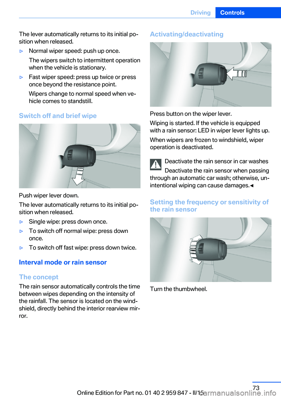
Switch off and brief wipe
Push wiper lever down.
The lever automatically returns to its initial po‐
sition when released.
▷Single wipe: press down once.▷To switch off normal wipe: press down
once.▷To switch off fast wipe: press down twice.
Interval mode or rain sensor
The concept The rain sensor automatically controls the time
between wipes depending on the intensity of the rainfall. The sensor is located on the wind‐
shield, directly behind the interior rearview mir‐
ror.
Activating/deactivating
Press button on the wiper lever.
Wiping is started. If the vehicle is equipped
with a rain sensor: LED in wiper lever lights up.
When wipers are frozen to windshield, wiper
operation is deactivated.
Deactivate the rain sensor in car washes
Deactivate the rain sensor when passing
through an automatic car wash; otherwise, un‐
intentional wiping can cause damages.◀
Setting the frequency or sensitivity of
the rain sensor
Turn the thumbwheel.
Seite 73DrivingControls73
Online Edition for Part no. 01 40 2 959 847 - II/15
Page 79 of 234
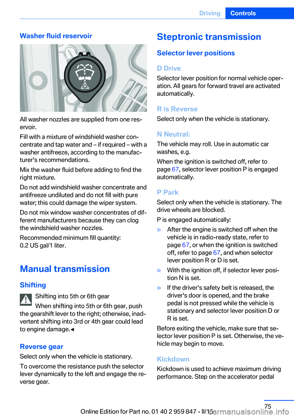
Washer fluid reservoir
All washer nozzles are supplied from one res‐
ervoir.
Fill with a mixture of windshield washer con‐
centrate and tap water and – if required – with a
washer antifreeze, according to the manufac‐
turer's recommendations.
Mix the washer fluid before adding to find the
right mixture.
Do not add windshield washer concentrate and
antifreeze undiluted and do not fill with pure
water; this could damage the wiper system.
Do not mix window washer concentrates of dif‐
ferent manufacturers because they can clog
the windshield washer nozzles.
Recommended minimum fill quantity:
0.2 US gal/1 liter.
Manual transmission
Shifting Shifting into 5th or 6th gear
When shifting into 5th or 6th gear, push
the gearshift lever to the right; otherwise, inad‐
vertent shifting into 3rd or 4th gear could lead
to engine damage.◀
Reverse gear Select only when the vehicle is stationary.
To overcome the resistance push the selector
lever dynamically to the left and engage the re‐
verse gear.
Steptronic transmission
Selector lever positions
D Drive Selector lever position for normal vehicle oper‐
ation. All gears for forward travel are activated
automatically.
R is Reverse
Select only when the vehicle is stationary.
N Neutral: The vehicle may roll. Use in automatic car
washes, e.g.
When the ignition is switched off, refer to
page 67, selector lever position P is engaged
automatically.
P Park Select only when the vehicle is stationary. The
drive wheels are blocked.
P is engaged automatically:▷After the engine is switched off when the
vehicle is in radio-ready state, refer to
page 67, or when the ignition is switched
off, refer to page 67, and when selector
lever position R or D is set.▷With the ignition off, if selector lever posi‐
tion N is set.▷If the driver's safety belt is released, the
driver's door is opened, and the brake
pedal is not pressed while the vehicle is
stationary and selector lever position D or
R is set.
Before exiting the vehicle, make sure that se‐
lector lever position P is set. Otherwise, the ve‐
hicle may begin to move.
Kickdown Kickdown is used to achieve maximum driving
performance. Step on the accelerator pedal
Seite 75DrivingControls75
Online Edition for Part no. 01 40 2 959 847 - II/15
Page 81 of 234
Once maximum engine speed is attained, M/S
manual mode is automatically upshifted as
needed.
Switching to manual mode▷To shift down: press the selector lever for‐
ward.▷To shift up: pull the selector lever rear‐
wards.
Gears will only be shifted at appropriate engine
and road speeds, for example downshifting is
not possible if the engine speed is too high.
The selected gear is briefly displayed in the in‐
strument cluster, followed by the currently se‐
lected gear.
Not M235i: Steptronic Sport transmission: prevent automatic
upshifting in M/S manual mode
The Steptronic Sport transmission does not
automatically upshift in M/S manual mode
once the maximum speed is reached, if one of
the following conditions is met:
▷DSC deactivated.▷TRACTION activated.▷SPORT+ activated.
In addition, the kickdown is deactivated.
With the respective transmission version, the
lowest possible gear can be selected by simul‐
taneously operating the kickdown and the left
shift paddle. However, this effect is not pro‐
duced via the shift paddles when switching
briefly from D to manual mode.
M235i: prevent automatic upshifting
in M/S manual mode
Once maximum engine speed is attained, up‐
shifting is not automatically performed in M/S
manual mode.
In addition, the kickdown is deactivated.
The lowest possible gear is selected by simul‐
taneously operating the kickdown and the left
shift paddle.
However, this effect is not produced via the
shift paddles when switching briefly from D to
manual mode.
Ending the sport program/manual
mode
Push the selector lever to the right.
D is displayed in the instrument cluster.
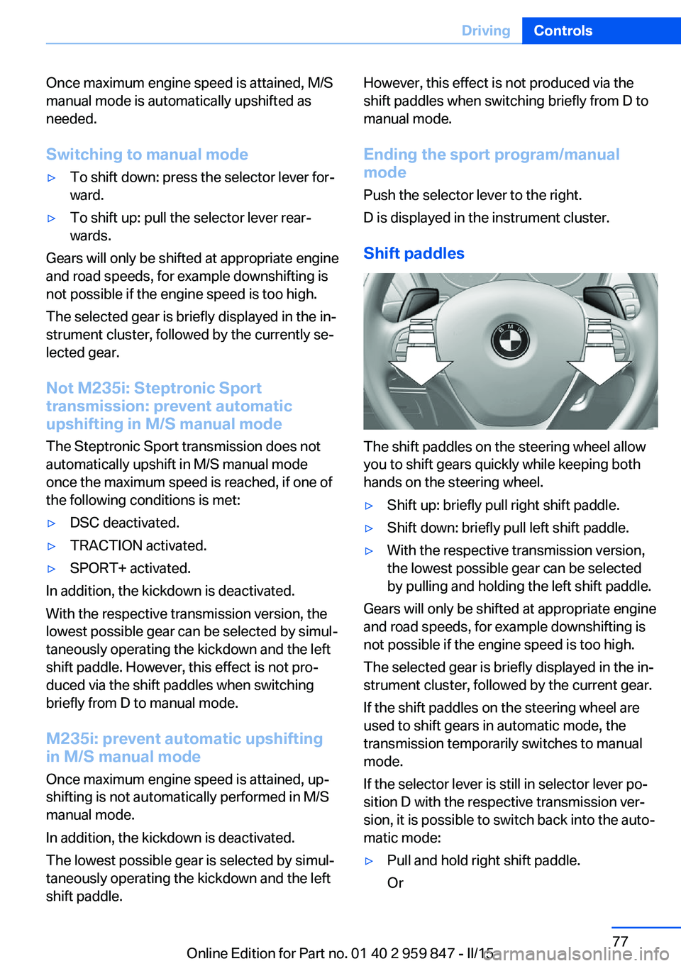
Shift paddles
The shift paddles on the steering wheel allow
you to shift gears quickly while keeping both
hands on the steering wheel.
▷Shift up: briefly pull right shift paddle.▷Shift down: briefly pull left shift paddle.▷With the respective transmission version,
the lowest possible gear can be selected
by pulling and holding the left shift paddle.
Gears will only be shifted at appropriate engine
and road speeds, for example downshifting is
not possible if the engine speed is too high.
The selected gear is briefly displayed in the in‐
strument cluster, followed by the current gear.
If the shift paddles on the steering wheel are
used to shift gears in automatic mode, the
transmission temporarily switches to manual
mode.
If the selector lever is still in selector lever po‐
sition D with the respective transmission ver‐
sion, it is possible to switch back into the auto‐
matic mode:
▷Pull and hold right shift paddle.
OrSeite 77DrivingControls77
Online Edition for Part no. 01 40 2 959 847 - II/15
Page 82 of 234
▷In addition to the briefly pulled right shift
paddle, briefly pull the left shift paddle.
In the manual mode, after conservative driving
for a certain amount of time or if there has
been no acceleration or shifting of the shift
paddles within a certain amount of time, the
transmission switches back to automatic
mode.
Displays in the instrument cluster The selector lever position is dis‐
played, e.g.: P.
Electronic unlocking of the
transmission lock
General information
Electronically unlock the transmission lock to
maneuver vehicle from the danger area.
Unlocking is possible, if the started can spin
the engine.
Engaging selector lever position N
1.Depress the brake pedal.2.Press the Start/Stop button. The starter
must audibly start.3.Press and hold the selector lever into posi‐
tion N.
A corresponding Check Control message
is displayed.4.Press the selector lever again into posi‐
tion N within approx. 6 seconds.
Position N is displayed in the instrument
cluster.5.Release brake, as soon as the starter
stops.6.Maneuver the vehicle from the danger area
and secure it against moving on its own.Steptronic Sport transmission:
Launch Control
The concept Launch Control enables optimum accelerationon surfaces with good traction.
Hints Component wear
Do not use Launch Control too often;
otherwise, this may result in premature wear of
components due to the high stress placed on
the vehicle.◀
Do not use Launch Control during the break-in,
refer to page 156, period.
To increase vehicle stability, activate DSC
again as soon as possible.
An experienced driver may be able to achieve
better acceleration values in DSC OFF mode.
Requirements Launch Control is available when the engine is
warmed up, that is, after uninterrupted driving
of at least 6 miles/10 km.
To start with Launch Control do not steer the
steering wheel.
Start with launch controlWhile the engine is running:1. Press button or select Sport+ with
the Driving Dynamics Control.
TRACTION is displayed in the instrument
cluster and the indicator lamp for DSC OFF
lights up.2.Engage selector lever position S.3.With the left foot, forcefully press down on
the brake.4.Press and hold down the accelerator pedal
beyond the resistance point at the full
throttle position.Seite 78ControlsDriving78
Online Edition for Part no. 01 40 2 959 847 - II/15
Page 86 of 234
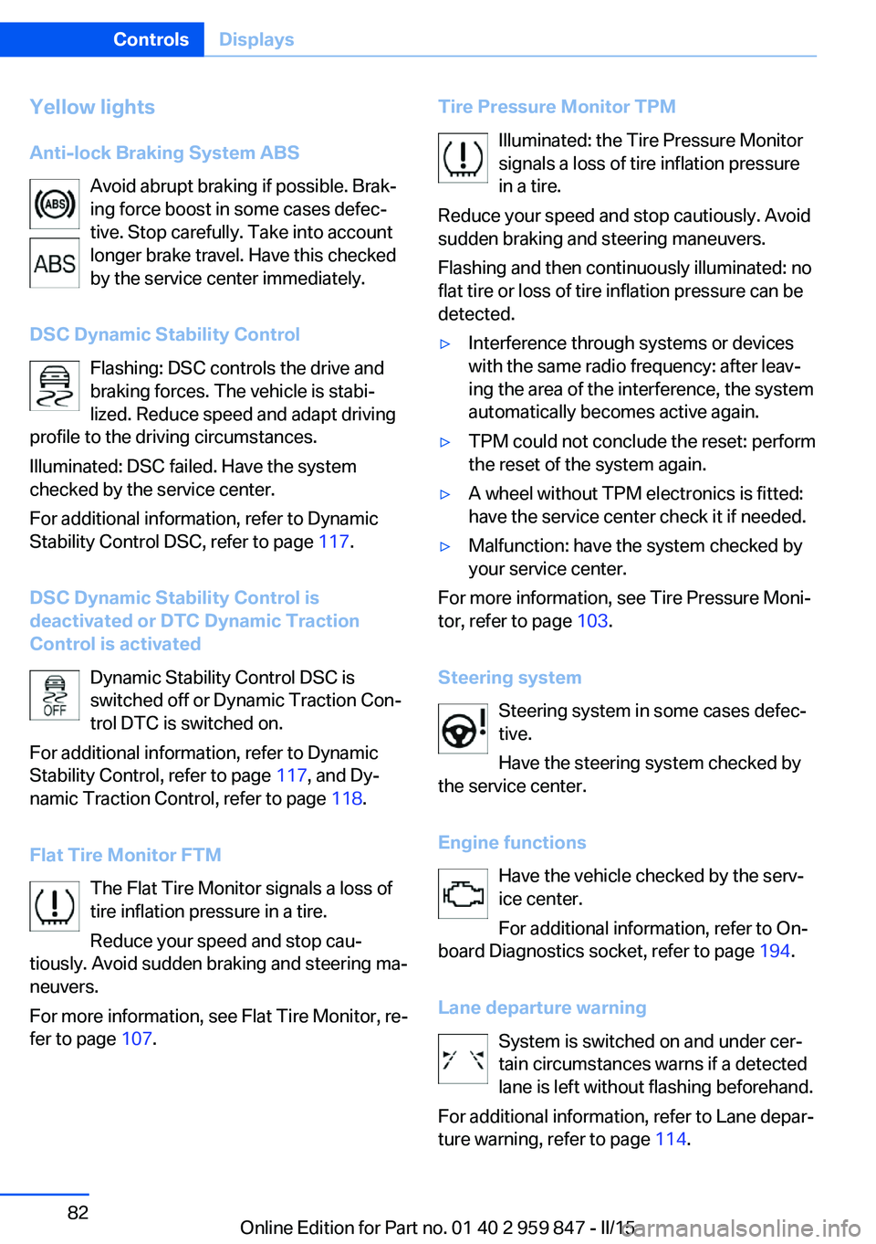
Yellow lights
Anti-lock Braking System ABS Avoid abrupt braking if possible. Brak‐
ing force boost in some cases defec‐
tive. Stop carefully. Take into account
longer brake travel. Have this checked
by the service center immediately.
DSC Dynamic Stability Control Flashing: DSC controls the drive and
braking forces. The vehicle is stabi‐
lized. Reduce speed and adapt driving
profile to the driving circumstances.
Illuminated: DSC failed. Have the system
checked by the service center.
For additional information, refer to Dynamic
Stability Control DSC, refer to page 117.
DSC Dynamic Stability Control is
deactivated or DTC Dynamic Traction
Control is activated
Dynamic Stability Control DSC is
switched off or Dynamic Traction Con‐
trol DTC is switched on.
For additional information, refer to Dynamic
Stability Control, refer to page 117, and Dy‐
namic Traction Control, refer to page 118.
Flat Tire Monitor FTM The Flat Tire Monitor signals a loss of
tire inflation pressure in a tire.
Reduce your speed and stop cau‐
tiously. Avoid sudden braking and steering ma‐
neuvers.
For more information, see Flat Tire Monitor, re‐
fer to page 107.Tire Pressure Monitor TPM
Illuminated: the Tire Pressure Monitorsignals a loss of tire inflation pressure
in a tire.
Reduce your speed and stop cautiously. Avoid
sudden braking and steering maneuvers.
Flashing and then continuously illuminated: no
flat tire or loss of tire inflation pressure can be
detected.▷Interference through systems or devices
with the same radio frequency: after leav‐
ing the area of the interference, the system
automatically becomes active again.▷TPM could not conclude the reset: perform
the reset of the system again.▷A wheel without TPM electronics is fitted:
have the service center check it if needed.▷Malfunction: have the system checked by
your service center.
For more information, see Tire Pressure Moni‐
tor, refer to page 103.
Steering system Steering system in some cases defec‐
tive.
Have the steering system checked by
the service center.
Engine functions Have the vehicle checked by the serv‐ice center.
For additional information, refer to On-
board Diagnostics socket, refer to page 194.
Lane departure warning System is switched on and under cer‐
tain circumstances warns if a detected
lane is left without flashing beforehand.
For additional information, refer to Lane depar‐
ture warning, refer to page 114.
Seite 82ControlsDisplays82
Online Edition for Part no. 01 40 2 959 847 - II/15
Page 87 of 234
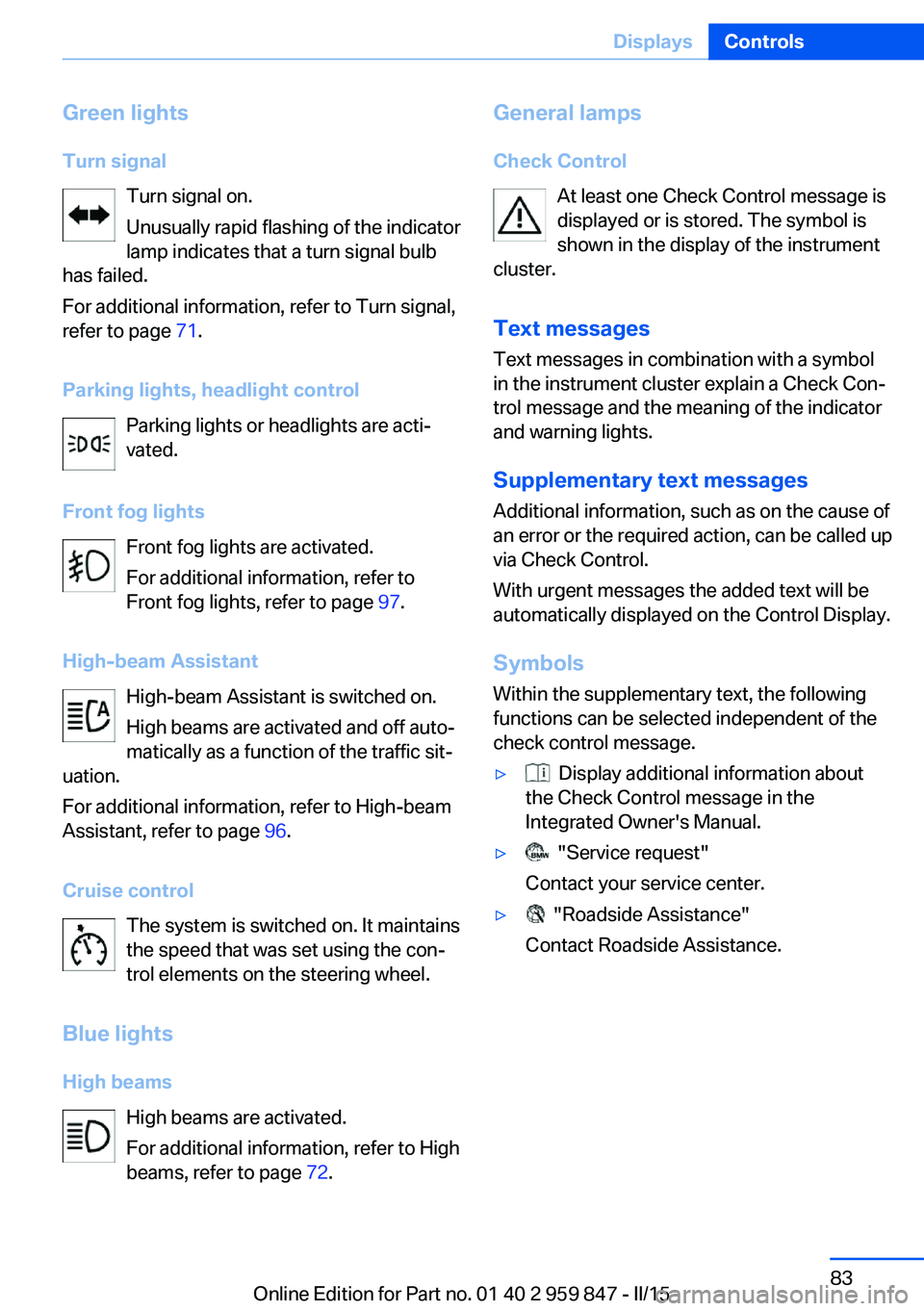
Green lights
Turn signal Turn signal on.
Unusually rapid flashing of the indicator
lamp indicates that a turn signal bulb
has failed.
For additional information, refer to Turn signal, refer to page 71.
Parking lights, headlight control Parking lights or headlights are acti‐
vated.
Front fog lights Front fog lights are activated.
For additional information, refer to
Front fog lights, refer to page 97.
High-beam Assistant High-beam Assistant is switched on.
High beams are activated and off auto‐
matically as a function of the traffic sit‐
uation.
For additional information, refer to High-beam
Assistant, refer to page 96.
Cruise control The system is switched on. It maintains
the speed that was set using the con‐
trol elements on the steering wheel.
Blue lights
High beams High beams are activated.
For additional information, refer to High
beams, refer to page 72.General lamps
Check Control At least one Check Control message is
displayed or is stored. The symbol is
shown in the display of the instrument
cluster.
Text messages
Text messages in combination with a symbol
in the instrument cluster explain a Check Con‐
trol message and the meaning of the indicator
and warning lights.
Supplementary text messages
Additional information, such as on the cause of
an error or the required action, can be called up
via Check Control.
With urgent messages the added text will be
automatically displayed on the Control Display.
Symbols
Within the supplementary text, the following
functions can be selected independent of the
check control message.▷ Display additional information about
the Check Control message in the
Integrated Owner's Manual.▷ "Service request"
Contact your service center.▷ "Roadside Assistance"
Contact Roadside Assistance.Seite 83DisplaysControls83
Online Edition for Part no. 01 40 2 959 847 - II/15
Page 88 of 234
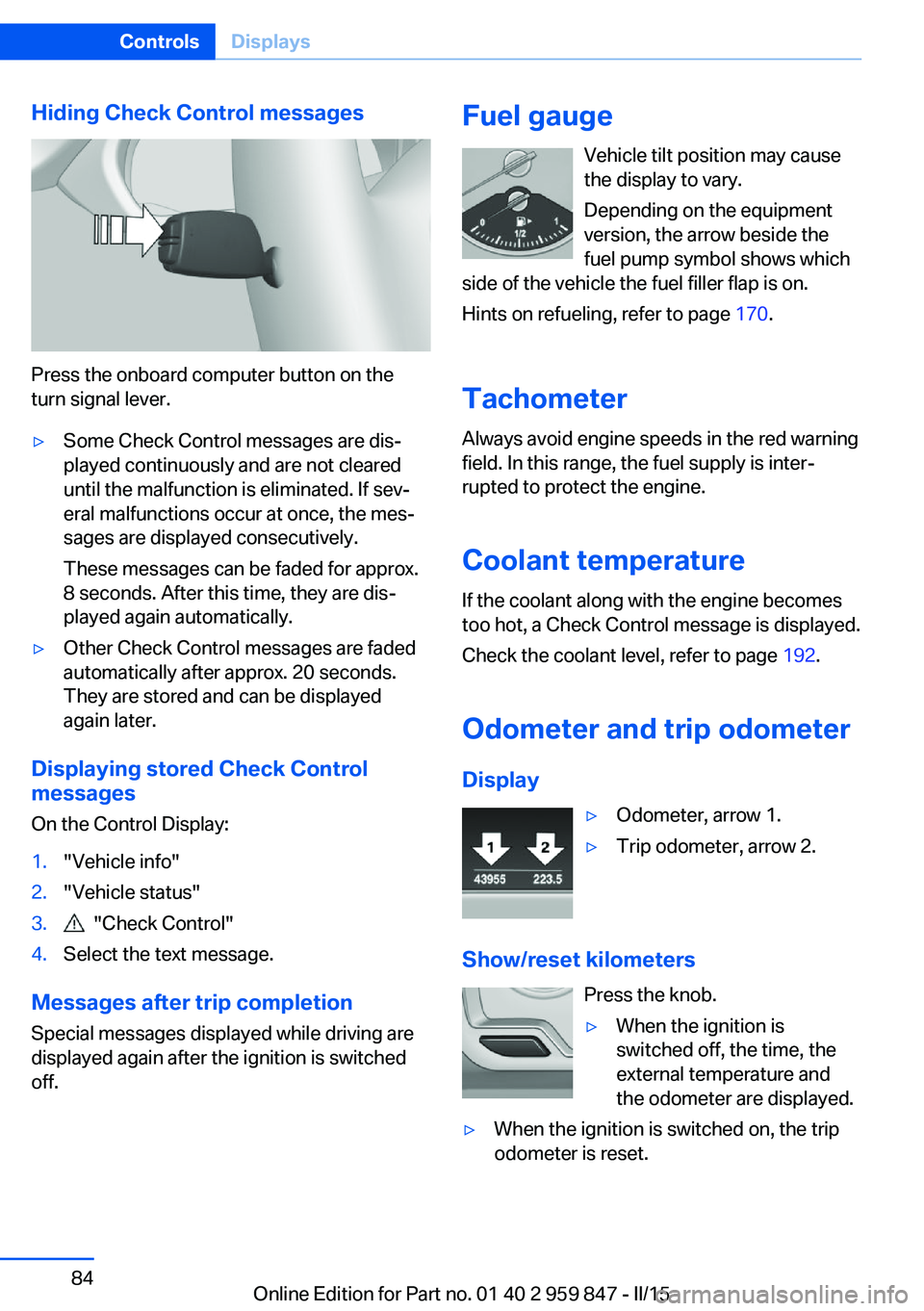
Hiding Check Control messages
Press the onboard computer button on the
turn signal lever.
▷Some Check Control messages are dis‐
played continuously and are not cleared
until the malfunction is eliminated. If sev‐
eral malfunctions occur at once, the mes‐
sages are displayed consecutively.
These messages can be faded for approx.
8 seconds. After this time, they are dis‐
played again automatically.▷Other Check Control messages are faded
automatically after approx. 20 seconds.
They are stored and can be displayed
again later.
Displaying stored Check Control
messages
On the Control Display:
1."Vehicle info"2."Vehicle status"3. "Check Control"4.Select the text message.
Messages after trip completion Special messages displayed while driving are
displayed again after the ignition is switched
off.
Fuel gauge
Vehicle tilt position may cause
the display to vary.
Depending on the equipment
version, the arrow beside the
fuel pump symbol shows which
side of the vehicle the fuel filler flap is on.
Hints on refueling, refer to page 170.
Tachometer
Always avoid engine speeds in the red warning
field. In this range, the fuel supply is inter‐
rupted to protect the engine.
Coolant temperature If the coolant along with the engine becomes
too hot, a Check Control message is displayed.
Check the coolant level, refer to page 192.
Odometer and trip odometer
Display▷Odometer, arrow 1.▷Trip odometer, arrow 2.
Show/reset kilometers Press the knob.
▷When the ignition is
switched off, the time, the
external temperature and
the odometer are displayed.▷When the ignition is switched on, the trip
odometer is reset.Seite 84ControlsDisplays84
Online Edition for Part no. 01 40 2 959 847 - II/15
Page 90 of 234
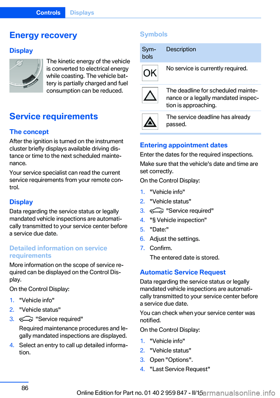
Energy recoveryDisplay The kinetic energy of the vehicle
is converted to electrical energy while coasting. The vehicle bat‐
tery is partially charged and fuel
consumption can be reduced.
Service requirements The concept
After the ignition is turned on the instrument
cluster briefly displays available driving dis‐
tance or time to the next scheduled mainte‐
nance.
Your service specialist can read the current
service requirements from your remote con‐
trol.
Display
Data regarding the service status or legally
mandated vehicle inspections are automati‐
cally transmitted to your service center before
a service due date.
Detailed information on service
requirements
More information on the scope of service re‐
quired can be displayed on the Control Dis‐
play.
On the Control Display:1."Vehicle info"2."Vehicle status"3. "Service required"
Required maintenance procedures and le‐
gally mandated inspections are displayed.4.Select an entry to call up detailed informa‐
tion.SymbolsSym‐
bolsDescriptionNo service is currently required.The deadline for scheduled mainte‐
nance or a legally mandated inspec‐
tion is approaching.The service deadline has already
passed.
Entering appointment dates
Enter the dates for the required inspections.
Make sure that the vehicle's date and time are
set correctly.
On the Control Display:
1."Vehicle info"2."Vehicle status"3. "Service required"4."§ Vehicle inspection"5."Date:"6.Adjust the settings.7.Confirm.
The entered date is stored.
Automatic Service Request
Data regarding the service status or legally
mandated vehicle inspections are automati‐
cally transmitted to your service center before
a service due date.
You can check when your service center was
notified.
On the Control Display:
1."Vehicle info"2."Vehicle status"3.Open "Options".4."Last Service Request"Seite 86ControlsDisplays86
Online Edition for Part no. 01 40 2 959 847 - II/15
Page 94 of 234
When destination guidance is activated in
the navigation system.
Adjusting the info display
Depending on the vehicle equipment version,
you can select what information from the com‐
puter is to be displayed on the info display of
the instrument cluster.
On the Control Display:
1."Settings"2."Instrument cluster"3.Select the desired displays.
Information in detail
Range
Displays the estimated cruising range available
with the remaining fuel.
It is calculated based on your driving style over
the last 20 miles/30 km.
Average fuel consumption
The average fuel consumption is calculated for
the period while the engine is running.
The average fuel consumption is calculated for
the distance traveled since the last reset by the
on-board comupter.
Average speed
Periods in which the vehicle is parked with the
engine manually stopped are not included in
the calculation of the average speed.
Resetting average values Press and hold the onboard computer button
on the turn signal lever.
Distance to destination
The distance remaining to the destination is
displayed if a destination is entered in the navi‐
gation system before the trip is started.
The distance to the destination is adopted au‐
tomatically.
Time of arrival The estimated time of arrival is
displayed if a destination is en‐
tered in the navigation system
before the trip is started.
The time must be correctly set. Speed limit detection
Description of the speed limit detection, refer
to page 87, function.
Trip computer The vehicle features two types of board com‐
puters.▷"Onboard info": the values can be reset as
often as necessary.▷"Trip computer": the values provide an
overview of the current trip.
Resetting the trip computer
On the Control Display:
1."Vehicle info"2."Trip computer"3."Reset": all values are reset.
"Automatically reset": all values are reset
approx. 4 hours after the vehicle came to a
standstill.
Display on the Control Display
Display the computer or trip computer on the
Control Display.
On the Control Display:
1."Vehicle info"2."Onboard info" or "Trip computer"Seite 90ControlsDisplays90
Online Edition for Part no. 01 40 2 959 847 - II/15
Page 96 of 234
6.Turn the controller until the desired mi‐
nutes are displayed.7.Press the controller.
The time is stored.
Setting the time format
1."Settings"2."Time/Date"3."Format:"4.Select the desired format.
The time format is stored.
Automatic time setting Depending on your vehicle's optional features,
the time, date and, if needed, the time zone are
updated automatically.
1."Settings"2."Time/Date"3."Auto time set"
Date
Setting the date
1."Settings"2."Time/Date"3."Date:"4.Turn the controller until the desired day is
displayed.5.Press the controller.6.Make the necessary settings for the month
and year.
The date is stored.
Setting the date format
1."Settings"2."Time/Date"3."Format:"4.Select the desired format.
The date format is stored.
Language
Setting the language
To set the language on the Control Display:1."Settings"2."Language/Units"3."Language:"4.Select the desired language.
Settings are stored for the profile currently in
use.
Setting the voice dialog
Voice dialog for the voice activation system,
refer to page 28.
Units of measure
Setting the units of measure
To set the units for fuel consumption, route/
distance and temperature:
1."Settings"2."Language/Units"3.Select the desired menu item.4.Select the desired unit.
Settings are stored for the profile currently in
use.
Brightness
Setting the brightness
To set the brightness of the Control Display:
1."Settings"2."Control display"3."Brightness"4.Turn the controller until the desired bright‐
ness is set.5.Press the controller.
Settings are stored for the profile currently in
use.
Seite 92ControlsDisplays92
Online Edition for Part no. 01 40 2 959 847 - II/15