service reset BMW 3 SERIES 1983 E30 User Guide
[x] Cancel search | Manufacturer: BMW, Model Year: 1983, Model line: 3 SERIES, Model: BMW 3 SERIES 1983 E30Pages: 228, PDF Size: 7.04 MB
Page 123 of 228
6
Chapter 6
Engine management and emission control systems
Catalytic converter . . . . . . . . . . . . . . . . . . . . . . . . . . . . . . . . . . . . . . 7
Electronic Control Unit (ECU) - removal and refitting . . . . . . . . . . . . 3
Evaporative emissions control (EVAP) system . . . . . . . . . . . . . . . . . 6
Evaporative emissions control system inspection . . . See Chapter 1
General information . . . . . . . . . . . . . . . . . . . . . . . . . . . . . . . . . . . . . . 1Information sensors . . . . . . . . . . . . . . . . . . . . . . . . . . . . . . . . . . . . . . 4
Motronic engine management system self-diagnosis -
general information . . . . . . . . . . . . . . . . . . . . . . . . . . . . . . . . . . . . 2
Positive crankcase ventilation (PCV) system . . . . . . . . . . . . . . . . . . 5
6•1
Easy,suitable for
novice with little
experienceFairly easy,suitable
for beginner with
some experienceFairly difficult,
suitable for competent
DIY mechanic
Difficult,suitable for
experienced DIY
mechanicVery difficult,
suitable for expert
DIY or professional
Degrees of difficulty Contents
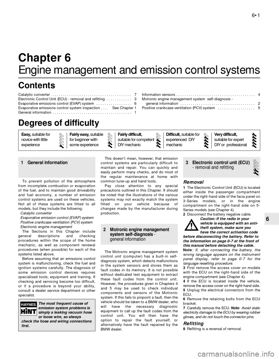
1 General information
To prevent pollution of the atmosphere
from incomplete combustion or evaporation
of the fuel, and to maintain good driveability
and fuel economy, a number of emission
control systems are used on these vehicles.
Not all of these systems are fitted to all
models, but they include the following:
Catalytic converter
Evaporative emission control (EVAP) system
Positive crankcase ventilation (PCV) system
Electronic engine management
The Sections in this Chapter include
general descriptions and checking
procedures within the scope of the home
mechanic, as well as component renewal
procedures (when possible) for each of the
systems listed above.
Before assuming that an emissions control
system is malfunctioning, check the fuel and
ignition systems carefully. The diagnosis of
some emission control devices requires
specialised tools, equipment and training. If
checking and servicing become too difficult,
or if a procedure is beyond your ability,
consult a dealer service department or other
specialist.This doesn’t mean, however, that emission
control systems are particularly difficult to
maintain and repair. You can quickly and
easily perform many checks, and do most of
the regular maintenance at home with
common tune-up and hand tools.
Pay close attention to any special
precautions outlined in this Chapter. It should
be noted that the illustrations of the various
systems may not exactly match the system
fitted on your vehicle because of
changes made by the manufacturer during
production.
2 Motronic engine management
system self-diagnosis-
general information
The Motronic engine management system
control unit (computer) has a built-in self-
diagnosis system, which detects malfunctions
in the system sensors and stores them as
fault codes in its memory. It is not possible
without dedicated test equipment to extract
these fault codes from the control unit.
However, the procedures given in Chapters 4
and 5 may be used to check individual
components and sensors of the Motronic
system. If this fails to pinpoint a fault, then the
vehicle should be taken to a BMW dealer, who
will have the necessary diagnostic
equipment to call up the fault codes from the
control unit. You will then have the
option to repair the fault yourself, or
alternatively have the fault repaired by the
BMW dealer.
3 Electronic control unit (ECU)
- removal and refitting
2
Removal
1The Electronic Control Unit (ECU) is located
either inside the passenger compartment
under the right-hand side of the facia panel on
3-Series models, or in the engine
compartment on the right-hand side on 5-
Series models (see Chapter 4).
2Disconnect the battery negative cable.
Caution: If the radio in your
vehicle is equipped with an anti-
theft system, make sure you
have the correct activation code
before disconnecting the battery. Refer to
the information on page 0-7 at the front of
this manual before detaching the cable.
Note: If, after connecting the battery, the
wrong language appears on the instrument
panel display, refer to page 0-7 for the
language resetting procedure.
3First remove the access cover on models
with the ECU on the right-hand side of the
engine compartment (see Chapter 4).
4If the ECU is located inside the vehicle,
remove the access cover on the right-hand side.
5Unplug the electrical connectors from the
ECU.
6Remove the retaining bolts from the ECU
bracket.
7Carefully remove the ECU. Note: Avoid static
electricity damage to the ECU by wearing rubber
gloves, and do not touch the connector pins.
Refitting
8Refitting is a reversal of removal.
The most frequent cause of
emission system problems is
simply a leaking vacuum hose
or loose wire, so always
check the hose and wiring connections
first.
Page 125 of 228
Check
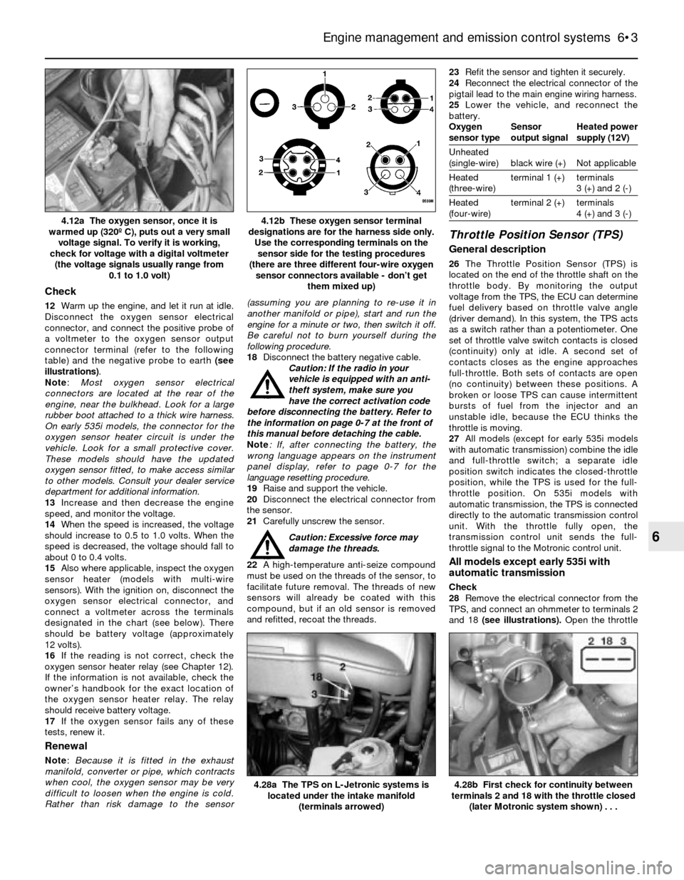
12Warm up the engine, and let it run at idle.
Disconnect the oxygen sensor electrical
connector, and connect the positive probe of
a voltmeter to the oxygen sensor output
connector terminal (refer to the following
table) and the negative probe to earth (see
illustrations).
Note:Most oxygen sensor electrical
connectors are located at the rear of the
engine, near the bulkhead. Look for a large
rubber boot attached to a thick wire harness.
On early 535i models, the connector for the
oxygen sensor heater circuit is under the
vehicle. Look for a small protective cover.
These models should have the updated
oxygen sensor fitted, to make access similar
to other models. Consult your dealer service
department for additional information.
13Increase and then decrease the engine
speed, and monitor the voltage.
14When the speed is increased, the voltage
should increase to 0.5 to 1.0 volts. When the
speed is decreased, the voltage should fall to
about 0 to 0.4 volts.
15Also where applicable, inspect the oxygen
sensor heater (models with multi-wire
sensors). With the ignition on, disconnect the
oxygen sensor electrical connector, and
connect a voltmeter across the terminals
designated in the chart (see below). There
should be battery voltage (approximately
12 volts).
16If the reading is not correct, check the
oxygen sensor heater relay (see Chapter 12).
If the information is not available, check the
owner’s handbook for the exact location of
the oxygen sensor heater relay. The relay
should receive battery voltage.
17If the oxygen sensor fails any of these
tests, renew it.
Renewal
Note: Because it is fitted in the exhaust
manifold, converter or pipe, which contracts
when cool, the oxygen sensor may be very
difficult to loosen when the engine is cold.
Rather than risk damage to the sensor(assuming you are planning to re-use it in
another manifold or pipe), start and run the
engine for a minute or two, then switch it off.
Be careful not to burn yourself during the
following procedure.
18Disconnect the battery negative cable.
Caution: If the radio in your
vehicle is equipped with an anti-
theft system, make sure you
have the correct activation code
before disconnecting the battery. Refer to
the information on page 0-7 at the front of
this manual before detaching the cable.
Note: If, after connecting the battery, the
wrong language appears on the instrument
panel display, refer to page 0-7 for the
language resetting procedure.
19Raise and support the vehicle.
20Disconnect the electrical connector from
the sensor.
21Carefully unscrew the sensor.
Caution: Excessive force may
damage the threads.
22A high-temperature anti-seize compound
must be used on the threads of the sensor, to
facilitate future removal. The threads of new
sensors will already be coated with this
compound, but if an old sensor is removed
and refitted, recoat the threads.23Refit the sensor and tighten it securely.
24Reconnect the electrical connector of the
pigtail lead to the main engine wiring harness.
25Lower the vehicle, and reconnect the
battery.
Oxygen Sensor Heated power
sensor type output signal supply (12V)
Unheated
(single-wire) black wire (+) Not applicable
Heated terminal 1 (+) terminals
(three-wire) 3 (+) and 2 (-)
Heated terminal 2 (+) terminals
(four-wire) 4 (+) and 3 (-)
Throttle Position Sensor (TPS)
General description
26The Throttle Position Sensor (TPS) is
located on the end of the throttle shaft on the
throttle body. By monitoring the output
voltage from the TPS, the ECU can determine
fuel delivery based on throttle valve angle
(driver demand). In this system, the TPS acts
as a switch rather than a potentiometer. One
set of throttle valve switch contacts is closed
(continuity) only at idle. A second set of
contacts closes as the engine approaches
full-throttle. Both sets of contacts are open
(no continuity) between these positions. A
broken or loose TPS can cause intermittent
bursts of fuel from the injector and an
unstable idle, because the ECU thinks the
throttle is moving.
27All models (except for early 535i models
with automatic transmission) combine the idle
and full-throttle switch; a separate idle
position switch indicates the closed-throttle
position, while the TPS is used for the full-
throttle position. On 535i models with
automatic transmission, the TPS is connected
directly to the automatic transmission control
unit. With the throttle fully open, the
transmission control unit sends the full-
throttle signal to the Motronic control unit.
All models except early 535i with
automatic transmission
Check
28Remove the electrical connector from the
TPS, and connect an ohmmeter to terminals 2
and 18 (see illustrations). Open the throttle
Engine management and emission control systems 6•3
4.12b These oxygen sensor terminal
designations are for the harness side only.
Use the corresponding terminals on the
sensor side for the testing procedures
(there are three different four-wire oxygen
sensor connectors available - don’t get
them mixed up)4.12a The oxygen sensor, once it is
warmed up (320º C), puts out a very small
voltage signal. To verify it is working,
check for voltage with a digital voltmeter
(the voltage signals usually range from
0.1 to 1.0 volt)
4.28b First check for continuity between
terminals 2 and 18 with the throttle closed
(later Motronic system shown) . . .4.28a The TPS on L-Jetronic systems is
located under the intake manifold
(terminals arrowed)
6
Page 158 of 228
Refitting
7Refitting is the reverse of removal. Tighten
the nuts and bolts securely. Adjust the
drivebelt tension (see Chapter 1).
8Top-up the fluid level in the reservoir (see
Chapter 1) and bleed the system (see Sec-
tion 23).
23 Power steering system-
bleeding
1
1To bleed the power steering system, begin
by checking the power steering fluid level and
adding fluid if necessary (see Chapter 1).
2Raise and support the front of the vehicle
on axle stands.
3Turn the steering wheel from lock-to-lock
several times. Recheck the fluid level and top
up if necessary.
4Start the engine and run it at 1000 rpm or
less. Turn the steering wheel from lock-to-
lock again (three or four times) and recheck
the fluid level one more time. Note:On 5-Series E28 (“old-shape”) models, pump the
brake pedal five or six times before turning the
steering wheel. Once the fluid level remains
constant, continue turning the wheel back and
forth until no more bubbles appear in the fluid
in the reservoir.
5Lower the vehicle to the ground. Run the
engine and again turn the wheels from lock-
to-lock several more times. Recheck the fluid
level. Position the wheels straight-ahead.24 Steering wheel-
removal and refitting
1
Warning: If the vehicle is
equipped with an airbag, do not
attempt this procedure. Have it
performed by a dealer service
department or other qualified specialist, as
there is a risk of injury if the airbag is
accidentally triggered.
Caution: If the radio in your
vehicle is equipped with an anti-
theft system, make sure you have
the correct activation code
before disconnecting the battery.
Note: If, after connecting the battery, the
wrong language appears on the instrument
panel display, refer to page 0-7 for the
language resetting procedure.
Removal
1Disconnect the battery negative cable.
2Using a small screwdriver, prise off the
BMW emblem in the centre of the steering
wheel.
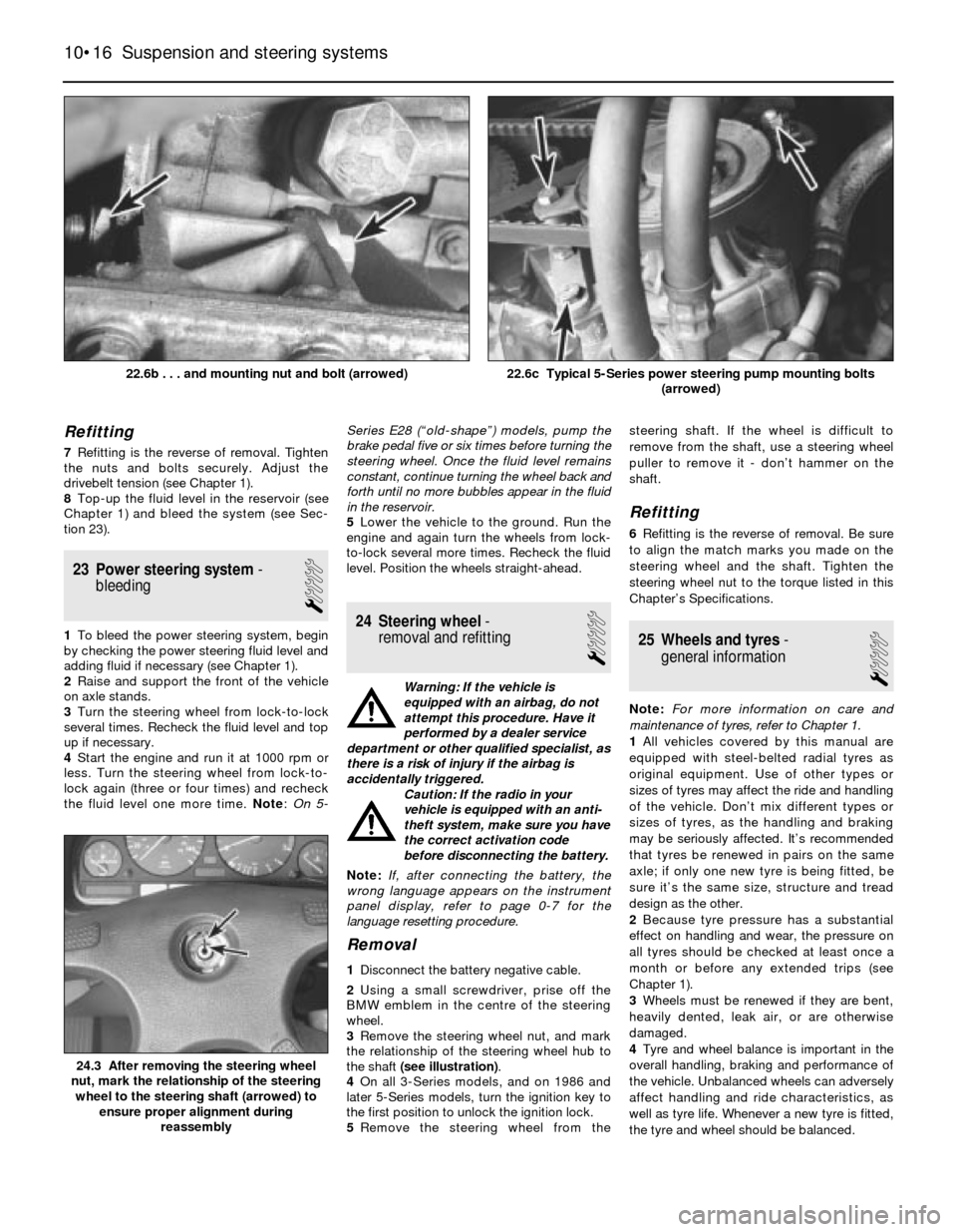
3Remove the steering wheel nut, and mark
the relationship of the steering wheel hub to
the shaft (see illustration).
4On all 3-Series models, and on 1986 and
later 5-Series models, turn the ignition key to
the first position to unlock the ignition lock.
5Remove the steering wheel from thesteering shaft. If the wheel is difficult to
remove from the shaft, use a steering wheel
puller to remove it - don’t hammer on the
shaft.
Refitting
6Refitting is the reverse of removal. Be sure
to align the match marks you made on the
steering wheel and the shaft. Tighten the
steering wheel nut to the torque listed in this
Chapter’s Specifications.
25 Wheels and tyres-
general information
1
Note:For more information on care and
maintenance of tyres, refer to Chapter 1.
1All vehicles covered by this manual are
equipped with steel-belted radial tyres as
original equipment. Use of other types or
sizes of tyres may affect the ride and handling
of the vehicle. Don’t mix different types or
sizes of tyres, as the handling and braking
may be seriously affected. It’s recommended
that tyres be renewed in pairs on the same
axle; if only one new tyre is being fitted, be
sure it’s the same size, structure and tread
design as the other.
2Because tyre pressure has a substantial
effect on handling and wear, the pressure on
all tyres should be checked at least once a
month or before any extended trips (see
Chapter 1).
3Wheels must be renewed if they are bent,
heavily dented, leak air, or are otherwise
damaged.
4Tyre and wheel balance is important in the
overall handling, braking and performance of
the vehicle. Unbalanced wheels can adversely
affect handling and ride characteristics, as
well as tyre life. Whenever a new tyre is fitted,
the tyre and wheel should be balanced.
10•16 Suspension and steering systems
24.3 After removing the steering wheel
nut, mark the relationship of the steering
wheel to the steering shaft (arrowed) to
ensure proper alignment during
reassembly
22.6c Typical 5-Series power steering pump mounting bolts
(arrowed)22.6b . . . and mounting nut and bolt (arrowed)
Page 169 of 228
12
Chapter 12 Body electrical systems
Bulb renewal . . . . . . . . . . . . . . . . . . . . . . . . . . . . . . . . . . . . . . . . . . . 15
Central locking system - description and check . . . . . . . . . . . . . . . . 20
Cruise control system - description and check . . . . . . . . . . . . . . . . 19
Direction indicator/hazard warning flasher - check and renewal . . . 5
Electric windows - description and check . . . . . . . . . . . . . . . . . . . . 21
Electrical system fault finding - general information . . . . . . . . . . . . . 2
Fuses - general information . . . . . . . . . . . . . . . . . . . . . . . . . . . . . . . 3
General information . . . . . . . . . . . . . . . . . . . . . . . . . . . . . . . . . . . . . . 1
Headlight housing - removal and refitting . . . . . . . . . . . . . . . . . . . . . 14
Headlights - adjustment . . . . . . . . . . . . . . . . . . . . . . . . . . . . . . . . . . 13
Headlights - bulb renewal . . . . . . . . . . . . . . . . . . . . . . . . . . . . . . . . . 12Heated rear window - check and repair . . . . . . . . . . . . . . . . . . . . . . 17
Ignition switch - removal and refitting . . . . . . . . . . . . . . . . . . . . . . . . 7
Instrument cluster - removal and refitting . . . . . . . . . . . . . . . . . . . . . 10
Radio - removal and refitting . . . . . . . . . . . . . . . . . . . . . . . . . . . . . . . 8
Radio aerial - removal and refitting . . . . . . . . . . . . . . . . . . . . . . . . . . 9
Relays - general information . . . . . . . . . . . . . . . . . . . . . . . . . . . . . . . 4
Service Indicator (SI) board - general information . . . . . . . . . . . . . . 11
Steering column switches - removal and refitting . . . . . . . . . . . . . . . 6
Supplemental Restraint System (SRS) - general information . . . . . . 18
Windscreen/tailgate wiper motor - removal and refitting . . . . . . . . . 16
Wiring diagrams - general information . . . . . . . . . . . . . . . . . . . . . . . 22
12•1
Easy,suitable for
novice with little
experienceFairly easy,suitable
for beginner with
some experienceFairly difficult,
suitable for competent
DIY mechanic
Difficult,suitable for
experienced DIY
mechanicVery difficult,
suitable for expert
DIY or professional
Degrees of difficulty Contents
1 General information
The chassis electrical system of this vehicle
is of 12-volt, negative earth type. Power for
the lights and all electrical accessories is
supplied by a lead/acid-type battery, which is
charged by the alternator.
This Chapter covers repair and service
procedures for various chassis (non-engine
related) electrical components. For
information regarding the engine electrical
system components (battery, alternator,
distributor and starter motor), see Chapter 5.
Warning: To prevent electrical
short-circuits, fires and injury,
always disconnect the battery
negative terminal before
checking, repairing or renewing electrical
components.
Caution: If the radio in your
vehicle is equipped with an anti-
theft system, make sure you have
the correct activation code
before disconnecting the battery, Refer to
the information on page 0-7 at the front of
this manual before detaching the cable.
Note: If, after connecting the battery, the
wrong language appears on the instrument
panel display, refer to page 0-7 for the
language resetting procedure.
2 Electrical system fault
finding- general information
2
A typical electrical circuit consists of an
electrical component, any switches, relays,
motors, fuses, fusible links or circuit breakers,
etc related to that component, and the wiring
and connectors that link the components to
both the battery and the chassis. To help you
pinpoint an electrical circuit problem, wiring
diagrams are included at the end of this book.
Before tackling any troublesome electrical
circuit, first study the appropriate wiring
diagrams to get a complete understanding of
what makes up that individual circuit.
Troublespots, for instance, can often be
isolated by noting if other components related
to that circuit are routed through the same
fuse and earth connections.
Electrical problems usually stem from
simple causes such as loose or corroded
connectors, a blown fuse, a melted fusible
link, or a bad relay. Inspect all fuses, wires
and connectors in a problem circuit first.
The basic tools needed include a circuit
tester, a high-impedance digital voltmeter, a
continuity tester and a jumper wire with an in-
line circuit breaker for bypassing electrical
components. Before attempting to locate or
define a problem with electrical testinstruments, use the wiring diagrams to
decide where to make the necessary
connections.
Voltage checks
Perform a voltage check first when a circuit
is not functioning properly. Connect one lead
of a circuit tester to either the negative battery
terminal or a known good earth.
Connect the other lead to a connector in
the circuit being tested, preferably nearest to
the battery or fuse. If the bulb of the tester
lights up, voltage is present, which means that
the part of the circuit between the connector
and the battery is problem-free. Continue
checking the rest of the circuit in the same
fashion.
When you reach a point at which no voltage
is present, the problem lies between that point
and the last test point with voltage. Most of
the time, problems can be traced to a loose
connection.Note:Keep in mind that some
circuits receive voltage only when the ignition
key is turned to a certain position.
Electrical fault diagnosis is simple if you
keep in mind that all electrical circuits are
basically electricity running from the battery,
through the wires, switches, relays, fuses and
fusible links to each electrical component
(light bulb, motor, etc) and then to earth, from
where it is passed back to the battery. Any
electrical problem is an interruption in the flow
of electricity to and from the battery.
Page 170 of 228
Finding a short-circuit
One method of finding a short-circuit is to
remove the fuse and connect a test light or
voltmeter in its place. There should be no
voltage present in the circuit. Move the
electrical connectors from side-to-side while
watching the test light. If the bulb goes on,
there is a short to earth somewhere in that
area, probably where the insulation has been
rubbed through. The same test can be
performed on each component in a circuit,
even a switch.
Earth check
Perform a earth check to see whether a
component is properly earthed (passing
current back via the vehicle body). Disconnect
the battery, and connect one lead of a self-
powered test light (often known as a
continuity tester) to a known good earth.
Connect the other lead to the wire or earth
connection being tested. The bulb should
light, indicating a good earth connection. If
not, dismantle the connection, and clean all
relevant parts thoroughly. When re-making
the connection, use serrated (shakeproof)
washers if possible, and tighten all bolts, etc,
securely.
Caution: If the radio in your
vehicle is equipped with an anti-
theft system, make sure you have
the correct activation code
before disconnecting the battery, Refer to
the information on page 0-7 at the front of
this manual before detaching the cable.
Note: If, after connecting the battery, the
wrong language appears on the instrument
panel display, refer to page 0-7 for the
language resetting procedure.
Continuity check
A continuity check determines if there are
any breaks in a circuit - if it is conducting
electricity properly. With the circuit off (no
power in the circuit), a self-powered continuity
tester can be used to check the circuit.
Connect the test leads to both ends of the
circuit, and if the test light comes on, the
circuit is passing current properly. If the light
doesn’t come on, there is a break somewhere
in the circuit. The same procedure can be
used to test a switch, by connecting the
continuity tester to the power-in and power-
out sides of the switch. With the switch turned
on, the test light should come on.
Finding an open-circuit
When diagnosing for possible open-
circuits, it is often difficult to locate them by
sight, because oxidation or terminal
misalignment are hidden by the connectors.
Intermittent problems are often caused by
oxidised or loose connections. Merely
wiggling an electrical connector may correct
the open-circuit condition, albeit temporarily.
Dismantle the connector, and spray with a
water-dispersant aerosol. On simpler
connectors, it may be possible to carefullybend the connector pins inside, to improve
the metal-to-metal contact - don’t damage
the connector in the process, however.
3 Fuses- general information
1
The electrical circuits of the vehicle are
protected by a combination of fuses and
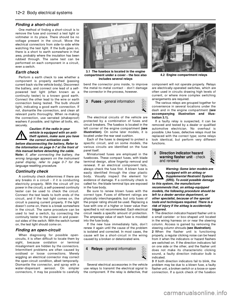
circuit breakers. The fusebox is located in the
left corner of the engine compartment (see
illustration). On some later models, it is
located under the rear seat cushion.
Each of the fuses is designed to protect a
specific circuit, and on some models, the
various circuits are identified on the fuse
panel itself.
Miniaturised fuses are employed in the
fuseboxes. These compact fuses, with blade
terminal design, allow fingertip removal and
renewal. If an electrical component fails,
always check the fuse first. A blown fuse is
easily identified through the clear plastic
body. Visually inspect the element for
evidence of damage. If a continuity check is
called for, the blade terminal tips are exposed
in the fuse body.
Be sure to renew blown fuses with the
correct type. Fuses of different ratings are
physically interchangeable, but only fuses of
the proper rating should be used. Replacing a
fuse with one of a higher or lower value than
specified is not recommended. Each electrical
circuit needs a specific amount of protection.
The amperage value of each fuse is moulded
into the fuse body.
If the new fuse immediately fails, don’t
renew it again until the cause of the problem
is isolated and corrected. In most cases, the
cause will be a short-circuit in the wiring
caused by a broken or deteriorated wire.
4 Relays- general information
1
Several electrical accessories in the vehicle
use relays to transmit the electrical signal to
the component. If the relay is defective, thatcomponent will not operate properly. Relays
are electrically-operated switches, which are
often used in circuits drawing high levels of
current, or where more complex switching
arrangements are required.
The various relays are grouped together for
convenience in several locations under the
dash and in the engine compartment (see
accompanying illustration and illus-
tration 3.1).
If a faulty relay is suspected, it can be
removed and tested by a dealer or qualified
automotive electrician. No overhaul is
possible. Like fuses, defective relays must be
replaced with the correct type; some relays
look identical, but perform very different
functions.
5 Direction indicator/hazard
warning flasher unit- check
and renewal
2
Warning: Some later models are
equipped with an airbag or
Supplemental Restraint System
(SRS). To avoid possible damage
to this system, the manufacturer
recommends that, on airbag-equipped
models, the following procedure should be
left to a dealer service department, or
other specialist, because of the special
tools and techniques required. There is a
risk of injury if the airbag is accidentally
triggered.
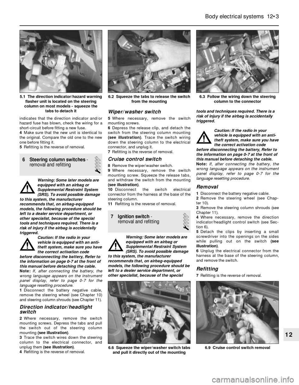
1The direction indicator/hazard flasher unit is
a small canister- or box-shaped unit located
in the wiring harness on or near the steering
column. Access is gained by removing the
steering column shrouds (see illustration).
2When the flasher unit is functioning
properly, a regular clicking noise can be heard
from it when the indicators or hazard flashers
are switched on. If the direction indicators fail
on one side or the other, and the flasher unit
does not make its characteristic clicking
sound, a faulty direction indicator bulb is
indicated.
3If both direction indicators fail to blink, the
problem may be due to a blown fuse, a faulty
flasher unit, a broken switch or a loose or open
connection. If a quick check of the fusebox
12•2 Body electrical systems
4.2 Engine compartment relays3.1 The fusebox is located in the engine
compartment under a cover - the box also
includes several relays
Page 171 of 228
indicates that the direction indicator and/or
hazard fuse has blown, check the wiring for a
short-circuit before fitting a new fuse.
4Make sure that the new unit is identical to
the original. Compare the old one to the new
one before fitting it.
5Refitting is the reverse of removal.
6 Steering column switches-
removal and refitting
1
Warning: Some later models are
equipped with an airbag or
Supplemental Restraint System
(SRS). To avoid possible damage
to this system, the manufacturer
recommends that, on airbag-equipped
models, the following procedure should be
left to a dealer service department, or
other specialist, because of the special
tools and techniques required. There is a
risk of injury if the airbag is accidentally
triggered.
Caution: If the radio in your
vehicle is equipped with an anti-
theft system, make sure you have
the correct activation code
before disconnecting the battery, Refer to
the information on page 0-7 at the front of
this manual before detaching the cable.
Note: If, after connecting the battery, the
wrong language appears on the instrument
panel display, refer to page 0-7 for the
language resetting procedure.
1Disconnect the battery negative cable,
remove the steering wheel (see Chapter 10)
and steering column shrouds (see Chapter 11).
Direction indicator/headlight
switch
2Where necessary, remove the switch
mounting screws. Depress the tabs and pull
the switch out of the steering column
mounting (see illustration).
3Trace the switch wires down the steering
column to the electrical connector, and
unplug them (see illustration).
4Refitting is the reverse of removal.
Wiper/washer switch
5Where necessary, remove the switch
mounting screws.
6Depress the release clip, and detach the
switch from the steering column mounting
(see illustration). Trace the switch wiring
down the steering column to the electrical
connector, and unplug it.
7Refitting is the reverse of removal.
Cruise control switch
8Remove the wiper/washer switch.
9Where necessary, remove the switch
mounting screw. Squeeze the release tabs,
and withdraw the switch from the mounting
(see illustration).
10Disconnect the switch electrical
connector from the harness at the base of the
steering column.
11Refitting is the reverse of removal.
7 Ignition switch-
removal and refitting
1
Warning: Some later models are
equipped with an airbag or
Supplemental Restraint System
(SRS). To avoid possible damage
to this system, the manufacturer
recommends that, on airbag-equipped
models, the following procedure should be
left to a dealer service department, or
other specialist, because of the specialtools and techniques required. There is a
risk of injury if the airbag is accidentally
triggered.
Caution: If the radio in your
vehicle is equipped with an anti-
theft system, make sure you have
the correct activation code
before disconnecting the battery, Refer to
the information on page 0-7 at the front of
this manual before detaching the cable.
Note: If, after connecting the battery, the
wrong language appears on the instrument
panel display, refer to page 0-7 for the
language resetting procedure.
Removal
1Disconnect the battery negative cable.
2Remove the steering wheel (see Chap-
ter 10).
3Remove the steering column shrouds (see
Chapter 11).
4Where necessary, remove the direction
indicator/headlight control switch (see Sec-
tion 6).
5Detach the clips by inserting a small
screwdriver into the openings on the sides
while pulling out on the switch (see
illustration).
6Unplug the electrical connector from the
harness at the base of the steering column,
and remove the switch.
Refitting
7Refitting is the reverse of removal.
Body electrical systems 12•3
6.3 Follow the wiring down the steering
column to the connector6.2 Squeeze the tabs to release the switch
from the mounting
6.9 Cruise control switch removal6.6 Squeeze the wiper/washer switch tabs
and pull it directly out of the mounting
12
5.1 The direction indicator/hazard warning
flasher unit is located on the steering
column on most models - squeeze the
tabs to detach it
Page 172 of 228
8 Radio- removal and refitting
1
Caution: If the radio in your
vehicle is equipped with an anti-
theft system, make sure you have
the correct activation code
before disconnecting the battery, Refer to
the information on page 0-7 at the front of
this manual before detaching the cable.
Note: If, after connecting the battery, the
wrong language appears on the instrument
panel display, refer to page 0-7 for the
language resetting procedure.
Removal
1Disconnect the battery negative cable.
2The radios on most models are held in place
by internal clips which are usually located at
the sides or corners of the unit faceplate.
Removal requires a special tool which is
inserted into the holes to release the clips so
the radio can be pulled out. These tools can be
fabricated from heavy wire, or are available
from your dealer or a car audio specialist. On
anti-theft radios, the clips are moved in and
out by internal screws which require another
type of tool. Insert the tool into the holes until
the clips release, then withdraw the radio from
the dash panel. Disconnect the wiring from the
radio and remove it.3On some models, the radio is held in place
by screws located beneath the faceplate. The
control knobs must be pulled off before the
faceplate can be withdrawn.
Refitting
4Refitting is the reverse of removal.
9 Aerial- removal and refitting
1
Caution: If the radio in your
vehicle is equipped with an anti-
theft system, make sure you have
the correct activation code
before disconnecting the battery, Refer to
the information on page 0-7 at the front of
this manual before detaching the cable.
Note: If, after connecting the battery, the
wrong language appears on the instrument
panel display, refer to page 0-7 for the
language resetting procedure.
Removal
1Disconnect the battery negative cable.
2Use circlip pliers to unscrew the aerial
mounting nut.
3Open the boot lid/tailgate and remove the
left side trim panel. On some models, the jack
and tail light cluster cover will have to be
removed first.
4Unplug the aerial power and radio lead
connectors (as applicable), remove the
retaining bolts, and remove the aerial and
motor assembly.
Refitting
5Refitting is the reverse of removal.
10 Instrument cluster-
removal and refitting
2
Caution: The instrument cluster
and components are very
susceptible to damage from
static electricity. Make sure you
are earthed and have dischargedany static electricity (by touching an object
such as a metal water pipe) before
touching the cluster or components.
Caution: If the radio in your
vehicle is equipped with an anti-
theft system, make sure you have
the correct activation code
before disconnecting the battery, Refer to
the information on page 0-7 at the front of
this manual before detaching the cable.
Note: If, after connecting the battery, the
wrong language appears on the instrument
panel display, refer to page 0-7 for the
language resetting procedure.
Removal
1Disconnect the battery negative cable.
2As necessary, remove the steering column
shrouds and lower trim panel (see Chap-
ter 11).
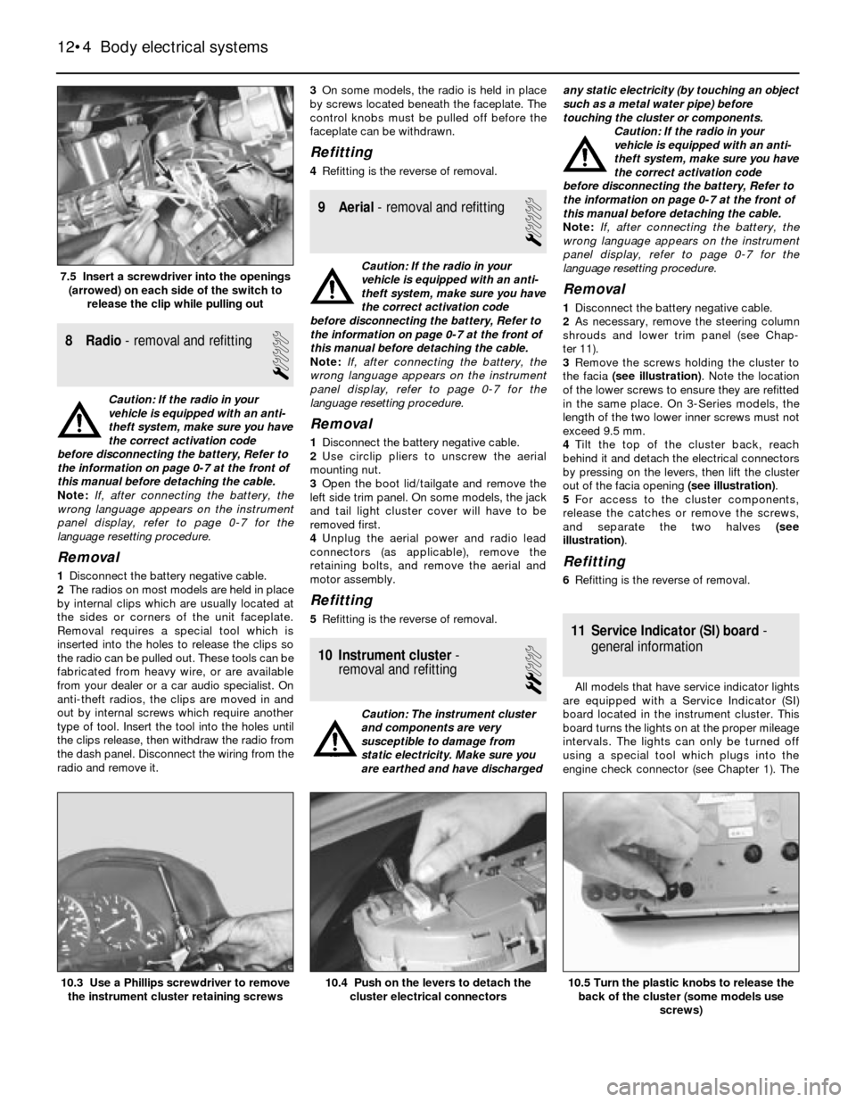
3Remove the screws holding the cluster to
the facia (see illustration). Note the location
of the lower screws to ensure they are refitted
in the same place. On 3-Series models, the
length of the two lower inner screws must not
exceed 9.5 mm.
4Tilt the top of the cluster back, reach
behind it and detach the electrical connectors
by pressing on the levers, then lift the cluster
out of the facia opening (see illustration).
5For access to the cluster components,
release the catches or remove the screws,
and separate the two halves (see
illustration).
Refitting
6Refitting is the reverse of removal.
11 Service Indicator (SI) board-
general information
All models that have service indicator lights
are equipped with a Service Indicator (SI)
board located in the instrument cluster. This
board turns the lights on at the proper mileage
intervals. The lights can only be turned off
using a special tool which plugs into the
engine check connector (see Chapter 1). The
12•4 Body electrical systems
10.5 Turn the plastic knobs to release the
back of the cluster (some models use
screws)10.4 Push on the levers to detach the
cluster electrical connectors10.3 Use a Phillips screwdriver to remove
the instrument cluster retaining screws
7.5 Insert a screwdriver into the openings
(arrowed) on each side of the switch to
release the clip while pulling out
Page 173 of 228
SI board is a self-contained computer which
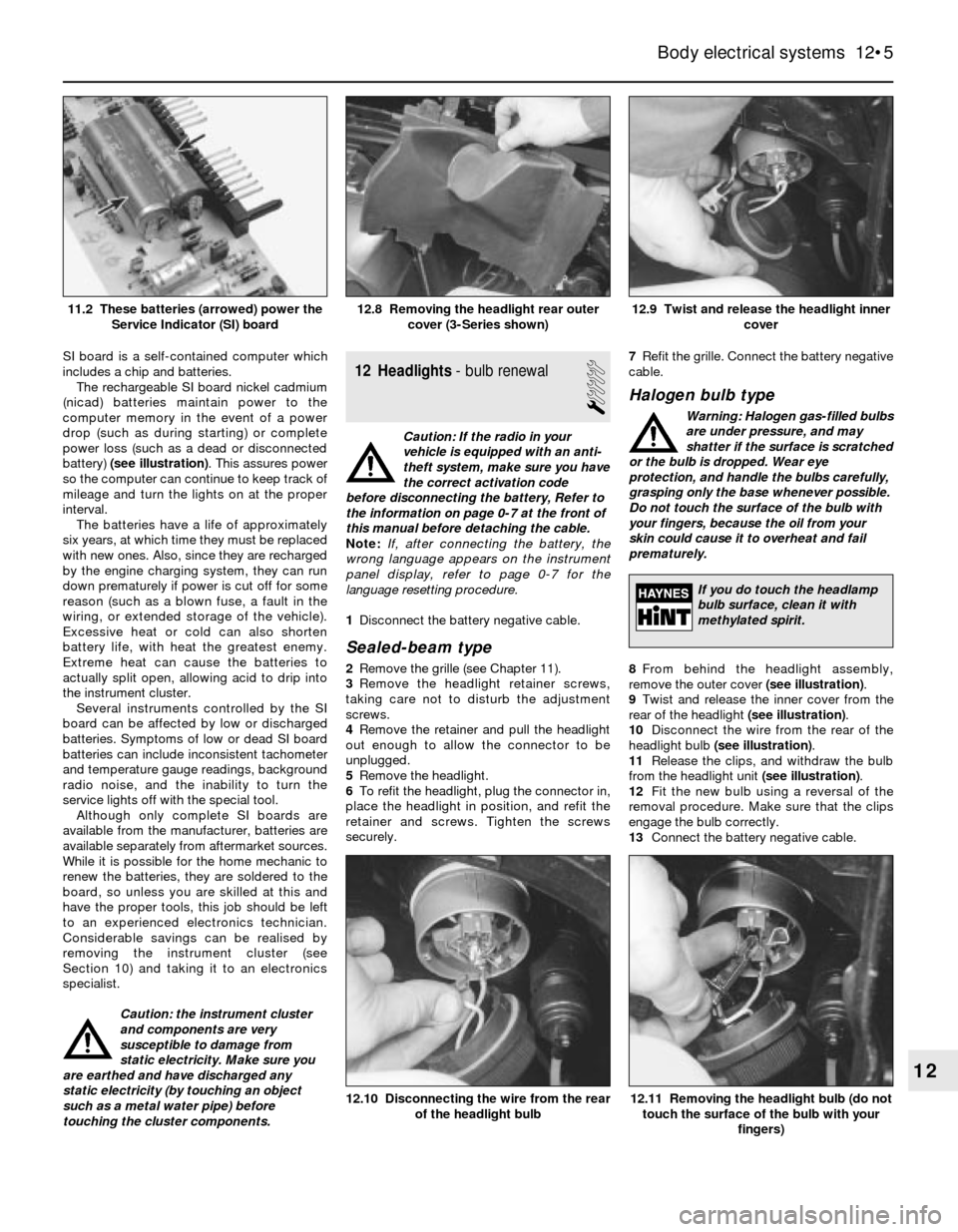
includes a chip and batteries.
The rechargeable SI board nickel cadmium
(nicad) batteries maintain power to the
computer memory in the event of a power
drop (such as during starting) or complete
power loss (such as a dead or disconnected
battery) (see illustration). This assures power
so the computer can continue to keep track of
mileage and turn the lights on at the proper
interval.
The batteries have a life of approximately
six years, at which time they must be replaced
with new ones. Also, since they are recharged
by the engine charging system, they can run
down prematurely if power is cut off for some
reason (such as a blown fuse, a fault in the
wiring, or extended storage of the vehicle).
Excessive heat or cold can also shorten
battery life, with heat the greatest enemy.
Extreme heat can cause the batteries to
actually split open, allowing acid to drip into
the instrument cluster.
Several instruments controlled by the SI
board can be affected by low or discharged
batteries. Symptoms of low or dead SI board
batteries can include inconsistent tachometer
and temperature gauge readings, background
radio noise, and the inability to turn the
service lights off with the special tool.
Although only complete SI boards are
available from the manufacturer, batteries are
available separately from aftermarket sources.
While it is possible for the home mechanic to
renew the batteries, they are soldered to the
board, so unless you are skilled at this and
have the proper tools, this job should be left
to an experienced electronics technician.
Considerable savings can be realised by
removing the instrument cluster (see
Section 10) and taking it to an electronics
specialist.
Caution: the instrument cluster
and components are very
susceptible to damage from
static electricity. Make sure you
are earthed and have discharged any
static electricity (by touching an object
such as a metal water pipe) before
touching the cluster components.12 Headlights- bulb renewal
1
Caution: If the radio in your
vehicle is equipped with an anti-
theft system, make sure you have
the correct activation code
before disconnecting the battery, Refer to
the information on page 0-7 at the front of
this manual before detaching the cable.
Note: If, after connecting the battery, the
wrong language appears on the instrument
panel display, refer to page 0-7 for the
language resetting procedure.
1Disconnect the battery negative cable.
Sealed-beam type
2Remove the grille (see Chapter 11).
3Remove the headlight retainer screws,
taking care not to disturb the adjustment
screws.
4Remove the retainer and pull the headlight
out enough to allow the connector to be
unplugged.
5Remove the headlight.
6To refit the headlight, plug the connector in,
place the headlight in position, and refit the
retainer and screws. Tighten the screws
securely.7Refit the grille. Connect the battery negative
cable.
Halogen bulb type
Warning: Halogen gas-filled bulbs
are under pressure, and may
shatter if the surface is scratched
or the bulb is dropped. Wear eye
protection, and handle the bulbs carefully,
grasping only the base whenever possible.
Do not touch the surface of the bulb with
your fingers, because the oil from your
skin could cause it to overheat and fail
prematurely.
8From behind the headlight assembly,
remove the outer cover (see illustration).
9Twist and release the inner cover from the
rear of the headlight (see illustration).
10Disconnect the wire from the rear of the
headlight bulb (see illustration).
11Release the clips, and withdraw the bulb
from the headlight unit (see illustration).
12Fit the new bulb using a reversal of the
removal procedure. Make sure that the clips
engage the bulb correctly.
13Connect the battery negative cable.
Body electrical systems 12•5
12.9 Twist and release the headlight inner
cover12.8 Removing the headlight rear outer
cover (3-Series shown)11.2 These batteries (arrowed) power the
Service Indicator (SI) board
12.11 Removing the headlight bulb (do not
touch the surface of the bulb with your
fingers)12.10 Disconnecting the wire from the rear
of the headlight bulb
12
If you do touch the headlamp
bulb surface, clean it with
methylated spirit.
Page 174 of 228
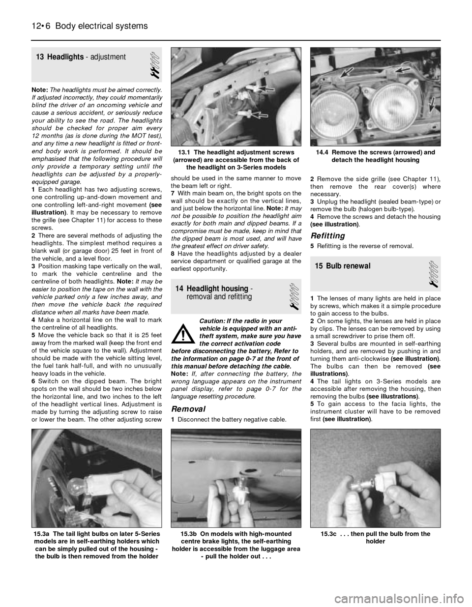
13 Headlights- adjustment
2
Note:The headlights must be aimed correctly.
If adjusted incorrectly, they could momentarily
blind the driver of an oncoming vehicle and
cause a serious accident, or seriously reduce
your ability to see the road. The headlights
should be checked for proper aim every
12 months (as is done during the MOT test),
and any time a new headlight is fitted or front-
end body work is performed. It should be
emphasised that the following procedure will
only provide a temporary setting until the
headlights can be adjusted by a properly-
equipped garage.
1Each headlight has two adjusting screws,
one controlling up-and-down movement and
one controlling left-and-right movement (see
illustration). It may be necessary to remove
the grille (see Chapter 11) for access to these
screws.
2There are several methods of adjusting the
headlights. The simplest method requires a
blank wall (or garage door) 25 feet in front of
the vehicle, and a level floor.
3Position masking tape vertically on the wall,
to mark the vehicle centreline and the
centreline of both headlights. Note:It may be
easier to position the tape on the wall with the
vehicle parked only a few inches away, and
then move the vehicle back the required
distance when all marks have been made.
4Make a horizontal line on the wall to mark
the centreline of all headlights.
5Move the vehicle back so that it is 25 feet
away from the marked wall (keep the front end
of the vehicle square to the wall). Adjustment
should be made with the vehicle sitting level,
the fuel tank half-full, and with no unusually
heavy loads in the vehicle.
6Switch on the dipped beam. The bright
spots on the wall should be two inches below
the horizontal line, and two inches to the left
of the headlight vertical lines. Adjustment is
made by turning the adjusting screw to raise
or lower the beam. The other adjusting screwshould be used in the same manner to move
the beam left or right.
7With main beam on, the bright spots on the
wall should be exactly on the vertical lines,
and just below the horizontal line. Note:It may
not be possible to position the headlight aim
exactly for both main and dipped beams. If a
compromise must be made, keep in mind that
the dipped beam is most used, and will have
the greatest effect on driver safety.
8Have the headlights adjusted by a dealer
service department or qualified garage at the
earliest opportunity.
14 Headlight housing-
removal and refitting
1
Caution: If the radio in your
vehicle is equipped with an anti-
theft system, make sure you have
the correct activation code
before disconnecting the battery, Refer to
the information on page 0-7 at the front of
this manual before detaching the cable.
Note: If, after connecting the battery, the
wrong language appears on the instrument
panel display, refer to page 0-7 for the
language resetting procedure.
Removal
1Disconnect the battery negative cable.2Remove the side grille (see Chapter 11),
then remove the rear cover(s) where
necessary.
3Unplug the headlight (sealed beam-type) or
remove the bulb (halogen bulb-type).
4Remove the screws and detach the housing
(see illustration).
Refitting
5Refitting is the reverse of removal.
15 Bulb renewal
1
1The lenses of many lights are held in place
by screws, which makes it a simple procedure
to gain access to the bulbs.
2On some lights, the lenses are held in place
by clips. The lenses can be removed by using
a small screwdriver to prise them off.
3Several bulbs are mounted in self-earthing
holders, and are removed by pushing in and
turning them anti-clockwise (see illustration).
The bulbs can then be removed (see
illustrations).
4The tail lights on 3-Series models are
accessible after removing the housing, then
removing the bulbs (see illustrations).
5To gain access to the facia lights, the
instrument cluster will have to be removed
first (see illustration).
12•6 Body electrical systems
15.3c . . . then pull the bulb from the
holder15.3b On models with high-mounted
centre brake lights, the self-earthing
holder is accessible from the luggage area
- pull the holder out . . .15.3a The tail light bulbs on later 5-Series
models are in self-earthing holders which
can be simply pulled out of the housing -
the bulb is then removed from the holder
14.4 Remove the screws (arrowed) and
detach the headlight housing13.1 The headlight adjustment screws
(arrowed) are accessible from the back of
the headlight on 3-Series models