wheel alignment BMW 3 SERIES 1983 E30 User Guide
[x] Cancel search | Manufacturer: BMW, Model Year: 1983, Model line: 3 SERIES, Model: BMW 3 SERIES 1983 E30Pages: 228, PDF Size: 7.04 MB
Page 159 of 228
26 Wheel alignment-
general information
4
Wheel alignment refers to the adjustments
made to the wheels so they are in proper
angular relationship to the suspension and the
road. Wheels that are out of proper alignment
not only affect vehicle control, but also
increase tyre wear. The front end angles
normally measured are camber, castor and
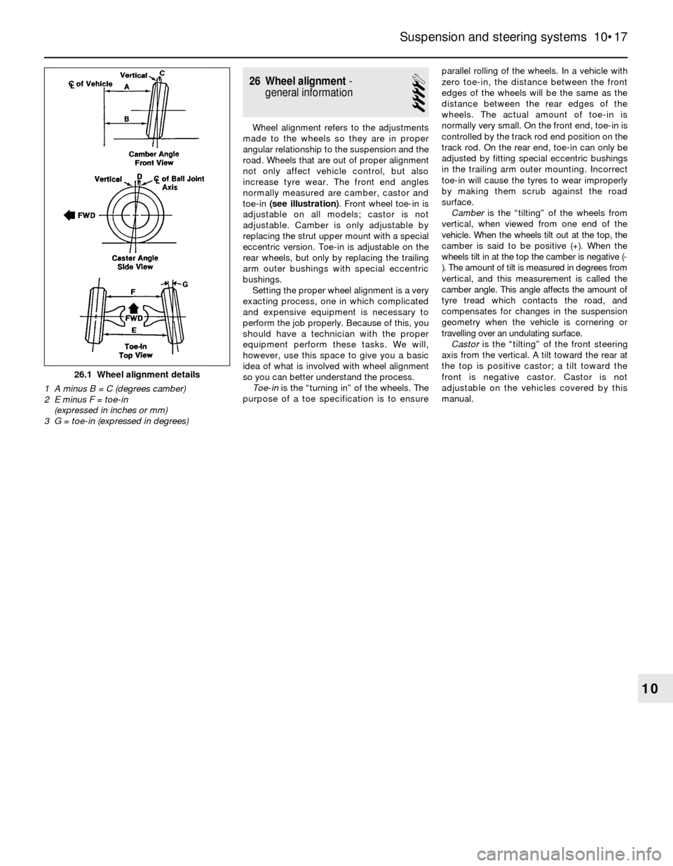
toe-in (see illustration). Front wheel toe-in is
adjustable on all models; castor is not
adjustable. Camber is only adjustable by
replacing the strut upper mount with a special
eccentric version. Toe-in is adjustable on the
rear wheels, but only by replacing the trailing
arm outer bushings with special eccentric
bushings.
Setting the proper wheel alignment is a very
exacting process, one in which complicated
and expensive equipment is necessary to
perform the job properly. Because of this, you
should have a technician with the proper
equipment perform these tasks. We will,
however, use this space to give you a basic
idea of what is involved with wheel alignment
so you can better understand the process.
Toe-inis the “turning in” of the wheels. The
purpose of a toe specification is to ensureparallel rolling of the wheels. In a vehicle with
zero toe-in, the distance between the front
edges of the wheels will be the same as the
distance between the rear edges of the
wheels. The actual amount of toe-in is
normally very small. On the front end, toe-in is
controlled by the track rod end position on the
track rod. On the rear end, toe-in can only be
adjusted by fitting special eccentric bushings
in the trailing arm outer mounting. Incorrect
toe-in will cause the tyres to wear improperly
by making them scrub against the road
surface.
Camberis the “tilting” of the wheels from
vertical, when viewed from one end of the
vehicle. When the wheels tilt out at the top, the
camber is said to be positive (+). When the
wheels tilt in at the top the camber is negative (-
). The amount of tilt is measured in degrees from
vertical, and this measurement is called the
camber angle. This angle affects the amount of
tyre tread which contacts the road, and
compensates for changes in the suspension
geometry when the vehicle is cornering or
travelling over an undulating surface.
Castoris the “tilting” of the front steering
axis from the vertical. A tilt toward the rear at
the top is positive castor; a tilt toward the
front is negative castor. Castor is not
adjustable on the vehicles covered by this
manual.
Suspension and steering systems 10•17
10
26.1 Wheel alignment details
1 A minus B = C (degrees camber)
2 E minus F = toe-in
(expressed in inches or mm)
3 G = toe-in (expressed in degrees)
Page 203 of 228
REF•2MOT Test Checks
Seat belts and seats
Note: The following checks are applicable to
all seat belts, front and rear.
MExamine the webbing of all the belts
(including rear belts if fitted) for cuts, serious
fraying or deterioration. Fasten and unfasten
each belt to check the buckles. If applicable,
check the retracting mechanism. Check the
security of all seat belt mountings accessible
from inside the vehicle.
MThe front seats themselves must be
securely attached and the backrests must
lock in the upright position.
Doors
MBoth front doors must be able to be opened
and closed from outside and inside, and must
latch securely when closed.
Vehicle identification
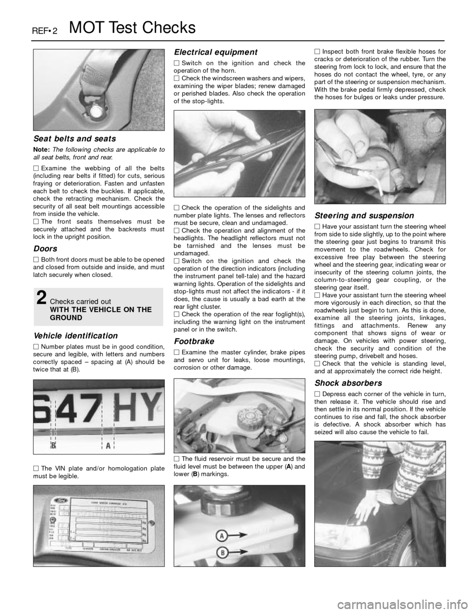
MNumber plates must be in good condition,
secure and legible, with letters and numbers
correctly spaced – spacing at (A) should be
twice that at (B).
MThe VIN plate and/or homologation plate
must be legible.
Electrical equipment
MSwitch on the ignition and check the
operation of the horn.
MCheck the windscreen washers and wipers,
examining the wiper blades; renew damaged
or perished blades. Also check the operation
of the stop-lights.
MCheck the operation of the sidelights and
number plate lights. The lenses and reflectors
must be secure, clean and undamaged.
MCheck the operation and alignment of the
headlights. The headlight reflectors must not
be tarnished and the lenses must be
undamaged.
MSwitch on the ignition and check the
operation of the direction indicators (including
the instrument panel tell-tale) and the hazard
warning lights. Operation of the sidelights and
stop-lights must not affect the indicators - if it
does, the cause is usually a bad earth at the
rear light cluster.
MCheck the operation of the rear foglight(s),
including the warning light on the instrument
panel or in the switch.
Footbrake
MExamine the master cylinder, brake pipes
and servo unit for leaks, loose mountings,
corrosion or other damage.
MThe fluid reservoir must be secure and the
fluid level must be between the upper (A) and
lower (B) markings.MInspect both front brake flexible hoses for
cracks or deterioration of the rubber. Turn the
steering from lock to lock, and ensure that the
hoses do not contact the wheel, tyre, or any
part of the steering or suspension mechanism.
With the brake pedal firmly depressed, check
the hoses for bulges or leaks under pressure.
Steering and suspension
MHave your assistant turn the steering wheel
from side to side slightly, up to the point where
the steering gear just begins to transmit this
movement to the roadwheels. Check for
excessive free play between the steering
wheel and the steering gear, indicating wear or
insecurity of the steering column joints, the
column-to-steering gear coupling, or the
steering gear itself.
MHave your assistant turn the steering wheel
more vigorously in each direction, so that the
roadwheels just begin to turn. As this is done,
examine all the steering joints, linkages,
fittings and attachments. Renew any
component that shows signs of wear or
damage. On vehicles with power steering,
check the security and condition of the
steering pump, drivebelt and hoses.
MCheck that the vehicle is standing level,
and at approximately the correct ride height.
Shock absorbers
MDepress each corner of the vehicle in turn,
then release it. The vehicle should rise and
then settle in its normal position. If the vehicle
continues to rise and fall, the shock absorber
is defective. A shock absorber which has
seized will also cause the vehicle to fail.
2Checks carried out
WITH THE VEHICLE ON THE
GROUND
Page 205 of 228
REF•4MOT Test Checks
MExamine the handbrake mechanism,
checking for frayed or broken cables,
excessive corrosion, or wear or insecurity of
the linkage. Check that the mechanism works
on each relevant wheel, and releases fully,
without binding.
MIt is not possible to test brake efficiency
without special equipment, but a road test can
be carried out later to check that the vehicle
pulls up in a straight line.
Fuel and exhaust systems
MInspect the fuel tank (including the filler
cap), fuel pipes, hoses and unions. All
components must be secure and free from
leaks.
MExamine the exhaust system over its entire
length, checking for any damaged, broken or
missing mountings, security of the retaining
clamps and rust or corrosion.
Wheels and tyres
MExamine the sidewalls and tread area of
each tyre in turn. Check for cuts, tears, lumps,
bulges, separation of the tread, and exposure
of the ply or cord due to wear or damage.
Check that the tyre bead is correctly seated
on the wheel rim, that the valve is sound andproperly seated, and that the wheel is not
distorted or damaged.
MCheck that the tyres are of the correct size
for the vehicle, that they are of the same size
and type on each axle, and that the pressures
are correct.
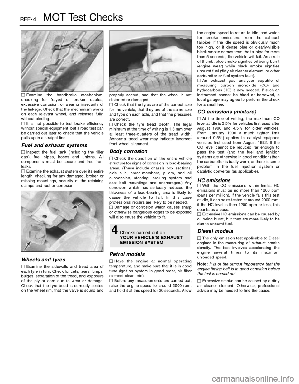
MCheck the tyre tread depth. The legal
minimum at the time of writing is 1.6 mm over
at least three-quarters of the tread width.
Abnormal tread wear may indicate incorrect
front wheel alignment.
Body corrosion
MCheck the condition of the entire vehicle
structure for signs of corrosion in load-bearing
areas. (These include chassis box sections,
side sills, cross-members, pillars, and all
suspension, steering, braking system and
seat belt mountings and anchorages.) Any
corrosion which has seriously reduced the
thickness of a load-bearing area is likely to
cause the vehicle to fail. In this case
professional repairs are likely to be needed.
MDamage or corrosion which causes sharp
or otherwise dangerous edges to be exposed
will also cause the vehicle to fail.
Petrol models
MHave the engine at normal operating
temperature, and make sure that it is in good
tune (ignition system in good order, air filter
element clean, etc).
MBefore any measurements are carried out,
raise the engine speed to around 2500 rpm,
and hold it at this speed for 20 seconds. Allowthe engine speed to return to idle, and watch
for smoke emissions from the exhaust
tailpipe. If the idle speed is obviously much
too high, or if dense blue or clearly-visible
black smoke comes from the tailpipe for more
than 5 seconds, the vehicle will fail. As a rule
of thumb, blue smoke signifies oil being burnt
(engine wear) while black smoke signifies
unburnt fuel (dirty air cleaner element, or other
carburettor or fuel system fault).
MAn exhaust gas analyser capable of
measuring carbon monoxide (CO) and
hydrocarbons (HC) is now needed. If such an
instrument cannot be hired or borrowed, a
local garage may agree to perform the check
for a small fee.
CO emissions (mixture)
MAt the time of writing, the maximum CO
level at idle is 3.5% for vehicles first used after
August 1986 and 4.5% for older vehicles.
From January 1996 a much tighter limit
(around 0.5%) applies to catalyst-equipped
vehicles first used from August 1992. If the
CO level cannot be reduced far enough to
pass the test (and the fuel and ignition
systems are otherwise in good condition) then
the carburettor is badly worn, or there is some
problem in the fuel injection system or
catalytic converter (as applicable).
HC emissionsMWith the CO emissions within limits, HC
emissions must be no more than 1200 ppm
(parts per million). If the vehicle fails this test
at idle, it can be re-tested at around 2000 rpm;
if the HC level is then 1200 ppm or less, this
counts as a pass.
MExcessive HC emissions can be caused by
oil being burnt, but they are more likely to be
due to unburnt fuel.
Diesel models
MThe only emission test applicable to Diesel
engines is the measuring of exhaust smoke
density. The test involves accelerating the
engine several times to its maximum
unloaded speed.
Note: It is of the utmost importance that the
engine timing belt is in good condition before
the test is carried out.
M
Excessive smoke can be caused by a dirty
air cleaner element. Otherwise, professional
advice may be needed to find the cause.
4Checks carried out on
YOUR VEHICLE’S EXHAUST
EMISSION SYSTEM
Page 215 of 228
REF•14Fault Finding
Brakes
Note:Before assuming that a brake problem exists, make sure that:
a) The tyres are in good condition and properly inflated (Chapter 1).
b) The wheel alignment (tracking) is correct (Chapter 10).
c) The vehicle is not loaded with weight in an unequal manner.
Vehicle pulls to one side during braking
m mIncorrect tyre pressures (Chapter 1).
m mWheel alignment (tracking) incorrect (Chapter 10)
m mUnmatched tyres on same axle.
m mRestricted brake lines or hoses (Chapter 9).
m mMalfunctioning caliper assembly (Chapter 9).
m mLoose suspension parts (Chapter 10).
m mLoose calipers (Chapter 9).
Noise (high-pitched squeal) when the brakes are
applied
m mFront and/or rear disc brake pads worn out. The noise comes from
the wear sensor rubbing against the disc. Renew the pads
immediately (Chapter 9).
Brake vibration (pedal pulsates)
Note:If the vehicle has ABS, it is normal for the brake pedal to pulsate
when the system is working.
m mExcessive lateral disc run-out (Chapter 9).
m mParallelism not within specifications (Chapter 9).
m mUneven pad wear - caused by caliper not sliding, due to improper
clearance or dirt (Chapter 9).
m mDefective disc (Chapter 9).
Excessive brake pedal travel
m
mPartial brake system failure (Chapter 9).
m mInsufficient fluid in master cylinder (Chapters 1 and 9).
m mAir trapped in system (Chapters 1 and 9).
Excessive pedal effort required to stop vehicle
m
mMalfunctioning brake servo unit (Chapter 9).
m mPartial system failure (Chapter 9).
m mExcessively-worn pads or shoes (Chapter 9).
m mCaliper piston stuck or sluggish (Chapter 9).
m mBrake pads contaminated with oil or grease (Chapter 9).
m mNew pads fitted and not yet seated. It will take a while for the new
material to seat against the disc.
Dragging brakes
m mMaster cylinder pistons not returning correctly (Chapter 9).
m mRestricted brakes lines or hoses (Chapters 1 and 9).
m mIncorrect handbrake adjustment (Chapter 9).
m mRear drum brake self-adjuster mechanism faulty (when applicable)
(Chapter 9).
Grabbing or uneven braking action
m mMalfunction of brake servo unit (Chapter 9).
m mBinding brake pedal mechanism (Chapter 9).
Brake pedal feels “spongy” when depressed
m
mAir in hydraulic lines (Chapter 9).
m mMaster cylinder mounting bolts loose (Chapter 9).
m mMaster cylinder defective (Chapter 9).
Brake pedal travels to the floor with little resistance
m
mLittle or no fluid in the master cylinder reservoir, caused by leaking
caliper piston(s), loose, damaged or disconnected brake lines
(Chapter 9).
Handbrake does not hold
m mHandbrake linkage incorrectly adjusted (Chapter 9).
m mHandbrake shoe linings worn out or contaminated (Chapter 9).
Page 216 of 228
REF•15
REF
Fault Finding
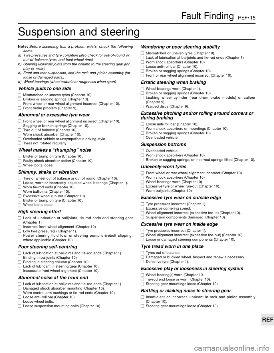
Suspension and steering
Note:Before assuming that a problem exists, check the following
items:
a) Tyre pressures and tyre condition (also check for out-of-round or
out-of-balance tyres, and bent wheel rims).
b) Steering universal joints from the column to the steering gear (for
play or wear).
c) Front and rear suspension, and the rack-and-pinion assembly (for
loose or damaged parts).
d) Wheel bearings (wheel wobble or roughness when spun).
Vehicle pulls to one side
m mMismatched or uneven tyres (Chapter 10).
m mBroken or sagging springs (Chapter 10).
m mFront wheel or rear wheel alignment incorrect (Chapter 10).
m mFront brake problem (Chapter 9).
Abnormal or excessive tyre wear
m
mFront wheel or rear wheel alignment incorrect (Chapter 10).
m mSagging or broken springs (Chapter 10).
m mTyre out of balance (Chapter 10).
m mWorn shock absorber (Chapter 10).
m mOverloaded vehicle or unsympathetic driving style.
m mTyres not rotated regularly.
Wheel makes a “thumping” noise
m
mBlister or bump on tyre (Chapter 10).
m mFaulty shock absorber action (Chapter 10).
m mWheel bolts loose.
Shimmy, shake or vibration
m
mTyre or wheel out of balance or out of round (Chapter 10).
m mLoose, worn or incorrectly-adjusted wheel bearings (Chapter 1).
m mWorn tie-rod ends (Chapter 10).
m mWorn balljoints (Chapter 10).
m mExcessive wheel run-out (Chapter 10).
m mBlister or bump on tyre (Chapter 10).
m mWheel bolts loose.
High steering effort
m
mLack of lubrication at balljoints, tie-rod ends and steering gear
(Chapter 1).
m mIncorrect front wheel alignment (Chapter 10).
m mLow tyre pressure(s) (Chapter 1).
m mPower steering fluid low, or steering pump drivebelt slipping,
where applicable (Chapter 10)
Poor steering self-centring
m mLack of lubrication at balljoints and tie-rod ends (Chapter 1).
m mBinding in balljoints (Chapter 10).
m mBinding in steering column (Chapter 10).
m mLack of lubricant in steering gear (Chapter 10).
m mInaccurate front wheel alignment (Chapter 10).
Abnormal noise at the front end
m
mLack of lubrication at balljoints and tie-rod ends (Chapter 1).
m mDamaged shock absorber mounting (Chapter 10).
m mWorn control arm bushings or tie-rod ends (Chapter 10).
m mLoose anti-roll bar (Chapter 10).
m mLoose wheel bolts.
m mLoose suspension mounting bolts (Chapter 10).
Wandering or poor steering stability
m
mMismatched or uneven tyres (Chapter 10).
m mLack of lubrication at balljoints and tie-rod ends (Chapter 1).
m mWorn shock absorbers (Chapter 10).
m mLoose anti-roll bar (Chapter 10).
m mBroken or sagging springs (Chapter 10).
m mFront or rear wheel alignment incorrect (Chapter 10).
Erratic steering when braking
m
mWheel bearings worn (Chapter 1).
m mBroken or sagging springs (Chapter 10).
m mLeaking wheel cylinder (rear drum brake models) or caliper
(Chapter 9).
m mWarped discs (Chapter 9).
Excessive pitching and/or rolling around corners or
during braking
m mLoose anti-roll bar (Chapter 10).
m mWorn shock absorbers or mountings (Chapter 10).
m mBroken or sagging springs (Chapter 10).
m mOverloaded vehicle.
Suspension bottoms
m
mOverloaded vehicle.
m mWorn shock absorbers (Chapter 10).
m mBroken or sagging springs, or incorrect springs fitted (Chapter 10).
Unevenly-worn tyres
m
mFront wheel or rear wheel alignment incorrect (Chapter 10).
m mWorn shock absorbers (Chapter 10).
m mWheel bearings worn (Chapter 10).
m mExcessive tyre or wheel run-out (Chapter 10).
m mWorn balljoints (Chapter 10).
Excessive tyre wear on outside edge
m
mTyre pressures incorrect (Chapter 1).
m mExcessive cornering speed.
m mWheel alignment incorrect (excessive toe-in) (Chapter 10).
m mSuspension components damaged (Chapter 10).
Excessive tyre wear on inside edge
m
mTyre pressures incorrect (Chapter 1).
m mWheel alignment incorrect (excessive toe-out) (Chapter 10).
m mLoose or damaged steering components (Chapter 10).
Tyre tread worn in one place
m
mTyres out of balance.
m mDamaged or buckled wheel. Inspect and renew if necessary.
m mDefective tyre (Chapter 1).
Excessive play or looseness in steering system
m
mWheel bearing(s) worn (Chapter 10.
m mTie-rod end loose or worn (Chapter 10).
m mSteering gear mountings loose (Chapter 10).
Rattling or clicking noise in steering gear
m
mInsufficient or incorrect lubricant in rack-and-pinion assembly
(Chapter 10).
m mSteering gear mountings loose (Chapter 10).
Page 221 of 228
REF•21
REF
Glossary of Technical Terms
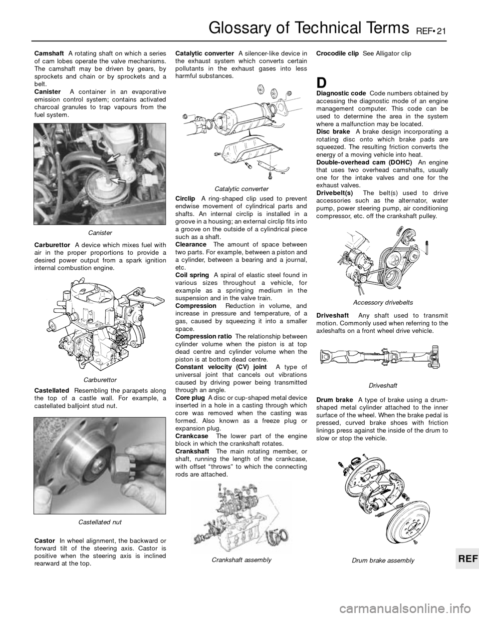
CamshaftA rotating shaft on which a series
of cam lobes operate the valve mechanisms.
The camshaft may be driven by gears, by
sprockets and chain or by sprockets and a
belt.
CanisterA container in an evaporative
emission control system; contains activated
charcoal granules to trap vapours from the
fuel system.
CarburettorA device which mixes fuel with
air in the proper proportions to provide a
desired power output from a spark ignition
internal combustion engine.
CastellatedResembling the parapets along
the top of a castle wall. For example, a
castellated balljoint stud nut.
CastorIn wheel alignment, the backward or
forward tilt of the steering axis. Castor is
positive when the steering axis is inclined
rearward at the top.Catalytic converterA silencer-like device in
the exhaust system which converts certain
pollutants in the exhaust gases into less
harmful substances.
CirclipA ring-shaped clip used to prevent
endwise movement of cylindrical parts and
shafts. An internal circlip is installed in a
groove in a housing; an external circlip fits into
a groove on the outside of a cylindrical piece
such as a shaft.
ClearanceThe amount of space between
two parts. For example, between a piston and
a cylinder, between a bearing and a journal,
etc.
Coil springA spiral of elastic steel found in
various sizes throughout a vehicle, for
example as a springing medium in the
suspension and in the valve train.
CompressionReduction in volume, and
increase in pressure and temperature, of a
gas, caused by squeezing it into a smaller
space.
Compression ratioThe relationship between
cylinder volume when the piston is at top
dead centre and cylinder volume when the
piston is at bottom dead centre.
Constant velocity (CV) jointA type of
universal joint that cancels out vibrations
caused by driving power being transmitted
through an angle.
Core plugA disc or cup-shaped metal device
inserted in a hole in a casting through which
core was removed when the casting was
formed. Also known as a freeze plug or
expansion plug.
CrankcaseThe lower part of the engine
block in which the crankshaft rotates.
CrankshaftThe main rotating member, or
shaft, running the length of the crankcase,
with offset “throws” to which the connecting
rods are attached.Crocodile clipSee Alligator clip
DDiagnostic codeCode numbers obtained by
accessing the diagnostic mode of an engine
management computer. This code can be
used to determine the area in the system
where a malfunction may be located.
Disc brakeA brake design incorporating a
rotating disc onto which brake pads are
squeezed. The resulting friction converts the
energy of a moving vehicle into heat.
Double-overhead cam (DOHC)An engine
that uses two overhead camshafts, usually
one for the intake valves and one for the
exhaust valves.
Drivebelt(s)The belt(s) used to drive
accessories such as the alternator, water
pump, power steering pump, air conditioning
compressor, etc. off the crankshaft pulley.
DriveshaftAny shaft used to transmit
motion. Commonly used when referring to the
axleshafts on a front wheel drive vehicle.
Drum brakeA type of brake using a drum-
shaped metal cylinder attached to the inner
surface of the wheel. When the brake pedal is
pressed, curved brake shoes with friction
linings press against the inside of the drum to
slow or stop the vehicle.
Castellated nut
Catalytic converter
Crankshaft assembly
Carburettor
Canister
Drum brake assembly
Accessory drivebelts
Driveshaft
Page 227 of 228

REF•27
REF
Index
R
Radiator - 3•3, 11•4
Radio - 12•4
Receiver-drier - 3•9
Regulator (voltage) - 5•10
Regulator (window) - 11•8
Relays - 12•2
Repair procedures - REF•8
Respraying - 11•3
Reversing light switch - 7B•4
Rocker arms - 2B•11
Rotor - 1•18
Routine maintenance and servicing- 1•1
et seq
Routine maintenance - air conditioning
system - 3•8
Routine maintenance - bodywork and
underframe - 11•1
Routine maintenance - hinges and locks -
11•4
Routine maintenance - interior trim - 11•2
Routine maintenance - upholstery and
carpets - 11•2
Rust holes in bodywork - 11•2
S
Safety first! - 0•5
Scalding - 0•5
Scratches in bodywork - 11•2
Screw threads and fastenings - REF•8
Seat belt - 11•9, REF•2
Seats - 11•9, REF•2
Selector lever - 7B•3, 7B•5
Selector shaft - 7A•2
Service Indicator (SI) board - 12•4
Service indicator light - 1•26
Servo - 9•2, 9•10, 9•11
Shock absorber - 1•21, 10•7, 10•8, 10•9,
REF•2, REF•3
Shoes - 9•7
Short-circuit - 12•2Silencer - 4•20
Slave cylinder - 8•3
Spares - REF•19
Spark plug - 1•17, 1•18
Speed sensors - 5•8
Springs - 10•7, 10•9, REF•3
Starter inhibitor - 7B•4
Starter motor - 5•12
Starter motor fault - REF•10
Starting system - 5•11
Steering box - 10•15
Steering column - 11•9, 12•3, REF•1
Steering gear - 10•12, 10•13, REF•3
Steering linkage - 10•14
Steering wheel - 10•16, REF•1
Stop-light switch - 9•13
Struts - 1•21, 10•6, 10•7
Sump - 2A•15
Supplemental Restraint System (SRS) -
12•8
Suspension and steering systems- 1•21,
1•22, 10•1et seq, REF•2, REF•3
Suspension and steering fault finding -
REF•15
Switches - 7B•4, 9•13, 12•3
T
Tailgate - 11•6
Tappets - 2B•11
Thermostat - 3•2
Thermotime switch - 4•17, 4•18
Throttle body - 4•16
Throttle linkage - 1•20
Throttle Position Sensor (TPS) - 6•3
Throttle positioner - 4•13, 4•14
Thrust arm - 10•5
Timing - 5•4
Timing belt - 1•26, 2A•8, 2A•9
Timing chain - 2A•6, 2A•8
Timing sensors - 6•4
Tools - REF•5, REF•7, REF•8
Top Dead Centre (TDC) for No 1 piston -
2A•3Torque converter - 7B•5
Towing - 0•8
Track rod ends - 10•13
Trailing arms - 10•10
Transmission - SeeManual transmission or
Automatic transmission
Trim - 11•2, 11•6
Tyres - 1•9, 1•14, 10•16, REF•4, REF•15
U
Underframe - 11•1
Universal joints - 8•8
Upholstery - 11•2
V
Vacuum hoses - 1•14
Vacuum servo - 9•10
Valve clearances - 1•19
Valve cover - 2A•4
Valves - 2B•10, 2B•11
Vehicle identification - REF•2, REF•19
Voltage checks - 12•1
Voltage regulator - 5•10
W
Washer fluid - 1•9
Water pump - 3•5
Weekly checks- 1•7et seq
Wheel alignment - 10•17
Wheel bearings - 10•8, 10•11, REF•3
Wheel changing - 0•8
Wheels - 10•16, REF•4
Windows - 11•8, 12•9
Windscreen - REF•1
Wiper blades - 1•23
Wiper motor - 12•7
Wiring diagrams- 12•9et seq
Working faclities - REF•7