display BMW 3 SERIES 1983 E30 Service Manual
[x] Cancel search | Manufacturer: BMW, Model Year: 1983, Model line: 3 SERIES, Model: BMW 3 SERIES 1983 E30Pages: 228, PDF Size: 7.04 MB
Page 168 of 228
19 Steering column shrouds -
removal and refitting
1
Caution: If the radio in your
vehicle is equipped with an anti-
theft system, make sure you have
the correct activation code
before disconnecting the battery, Refer to
the information on page 0-7 at the front of
this manual before detaching the cable.
Note: If, after connecting the battery, the
wrong language appears on the instrument
panel display, refer to page 0-7 for the
language resetting procedure.
Removal
1Disconnect the battery negative cable.
2Remove the steering wheel (Chapter 10).
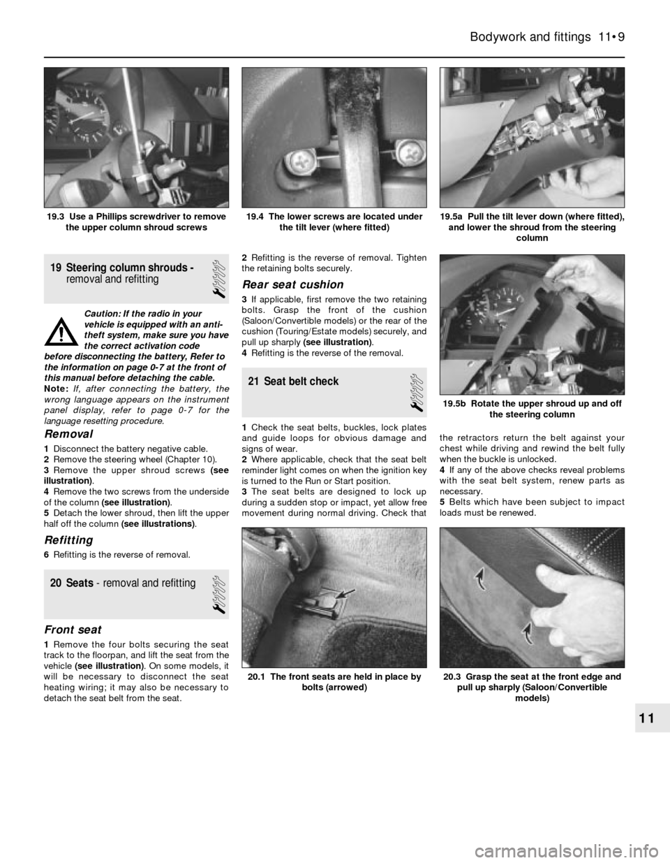
3Remove the upper shroud screws (see
illustration).
4Remove the two screws from the underside
of the column (see illustration).
5Detach the lower shroud, then lift the upper
half off the column (see illustrations).
Refitting
6Refitting is the reverse of removal.
20 Seats- removal and refitting
1
Front seat
1Remove the four bolts securing the seat
track to the floorpan, and lift the seat from the
vehicle (see illustration). On some models, it
will be necessary to disconnect the seat
heating wiring; it may also be necessary to
detach the seat belt from the seat.2Refitting is the reverse of removal. Tighten
the retaining bolts securely.
Rear seat cushion
3If applicable, first remove the two retaining
bolts. Grasp the front of the cushion
(Saloon/Convertible models) or the rear of the
cushion (Touring/Estate models) securely, and
pull up sharply (see illustration).
4Refitting is the reverse of the removal.
21 Seat belt check
1
1Check the seat belts, buckles, lock plates
and guide loops for obvious damage and
signs of wear.
2Where applicable, check that the seat belt
reminder light comes on when the ignition key
is turned to the Run or Start position.
3The seat belts are designed to lock up
during a sudden stop or impact, yet allow free
movement during normal driving. Check thatthe retractors return the belt against your
chest while driving and rewind the belt fully
when the buckle is unlocked.
4If any of the above checks reveal problems
with the seat belt system, renew parts as
necessary.
5Belts which have been subject to impact
loads must be renewed.
Bodywork and fittings 11•9
19.5a Pull the tilt lever down (where fitted),
and lower the shroud from the steering
column19.4 The lower screws are located under
the tilt lever (where fitted)19.3 Use a Phillips screwdriver to remove
the upper column shroud screws
20.3 Grasp the seat at the front edge and
pull up sharply (Saloon/Convertible
models)20.1 The front seats are held in place by
bolts (arrowed)
19.5b Rotate the upper shroud up and off
the steering column
11
Page 169 of 228
12
Chapter 12 Body electrical systems
Bulb renewal . . . . . . . . . . . . . . . . . . . . . . . . . . . . . . . . . . . . . . . . . . . 15
Central locking system - description and check . . . . . . . . . . . . . . . . 20
Cruise control system - description and check . . . . . . . . . . . . . . . . 19
Direction indicator/hazard warning flasher - check and renewal . . . 5
Electric windows - description and check . . . . . . . . . . . . . . . . . . . . 21
Electrical system fault finding - general information . . . . . . . . . . . . . 2
Fuses - general information . . . . . . . . . . . . . . . . . . . . . . . . . . . . . . . 3
General information . . . . . . . . . . . . . . . . . . . . . . . . . . . . . . . . . . . . . . 1
Headlight housing - removal and refitting . . . . . . . . . . . . . . . . . . . . . 14
Headlights - adjustment . . . . . . . . . . . . . . . . . . . . . . . . . . . . . . . . . . 13
Headlights - bulb renewal . . . . . . . . . . . . . . . . . . . . . . . . . . . . . . . . . 12Heated rear window - check and repair . . . . . . . . . . . . . . . . . . . . . . 17
Ignition switch - removal and refitting . . . . . . . . . . . . . . . . . . . . . . . . 7
Instrument cluster - removal and refitting . . . . . . . . . . . . . . . . . . . . . 10
Radio - removal and refitting . . . . . . . . . . . . . . . . . . . . . . . . . . . . . . . 8
Radio aerial - removal and refitting . . . . . . . . . . . . . . . . . . . . . . . . . . 9
Relays - general information . . . . . . . . . . . . . . . . . . . . . . . . . . . . . . . 4
Service Indicator (SI) board - general information . . . . . . . . . . . . . . 11
Steering column switches - removal and refitting . . . . . . . . . . . . . . . 6
Supplemental Restraint System (SRS) - general information . . . . . . 18
Windscreen/tailgate wiper motor - removal and refitting . . . . . . . . . 16
Wiring diagrams - general information . . . . . . . . . . . . . . . . . . . . . . . 22
12•1
Easy,suitable for
novice with little
experienceFairly easy,suitable
for beginner with
some experienceFairly difficult,
suitable for competent
DIY mechanic
Difficult,suitable for
experienced DIY
mechanicVery difficult,
suitable for expert
DIY or professional
Degrees of difficulty Contents
1 General information
The chassis electrical system of this vehicle
is of 12-volt, negative earth type. Power for
the lights and all electrical accessories is
supplied by a lead/acid-type battery, which is
charged by the alternator.
This Chapter covers repair and service
procedures for various chassis (non-engine
related) electrical components. For
information regarding the engine electrical
system components (battery, alternator,
distributor and starter motor), see Chapter 5.
Warning: To prevent electrical
short-circuits, fires and injury,
always disconnect the battery
negative terminal before
checking, repairing or renewing electrical
components.
Caution: If the radio in your
vehicle is equipped with an anti-
theft system, make sure you have
the correct activation code
before disconnecting the battery, Refer to
the information on page 0-7 at the front of
this manual before detaching the cable.
Note: If, after connecting the battery, the
wrong language appears on the instrument
panel display, refer to page 0-7 for the
language resetting procedure.
2 Electrical system fault
finding- general information
2
A typical electrical circuit consists of an
electrical component, any switches, relays,
motors, fuses, fusible links or circuit breakers,
etc related to that component, and the wiring
and connectors that link the components to
both the battery and the chassis. To help you
pinpoint an electrical circuit problem, wiring
diagrams are included at the end of this book.
Before tackling any troublesome electrical
circuit, first study the appropriate wiring
diagrams to get a complete understanding of
what makes up that individual circuit.
Troublespots, for instance, can often be
isolated by noting if other components related
to that circuit are routed through the same
fuse and earth connections.
Electrical problems usually stem from
simple causes such as loose or corroded
connectors, a blown fuse, a melted fusible
link, or a bad relay. Inspect all fuses, wires
and connectors in a problem circuit first.
The basic tools needed include a circuit
tester, a high-impedance digital voltmeter, a
continuity tester and a jumper wire with an in-
line circuit breaker for bypassing electrical
components. Before attempting to locate or
define a problem with electrical testinstruments, use the wiring diagrams to
decide where to make the necessary
connections.
Voltage checks
Perform a voltage check first when a circuit
is not functioning properly. Connect one lead
of a circuit tester to either the negative battery
terminal or a known good earth.
Connect the other lead to a connector in
the circuit being tested, preferably nearest to
the battery or fuse. If the bulb of the tester
lights up, voltage is present, which means that
the part of the circuit between the connector
and the battery is problem-free. Continue
checking the rest of the circuit in the same
fashion.
When you reach a point at which no voltage
is present, the problem lies between that point
and the last test point with voltage. Most of
the time, problems can be traced to a loose
connection.Note:Keep in mind that some
circuits receive voltage only when the ignition
key is turned to a certain position.
Electrical fault diagnosis is simple if you
keep in mind that all electrical circuits are
basically electricity running from the battery,
through the wires, switches, relays, fuses and
fusible links to each electrical component
(light bulb, motor, etc) and then to earth, from
where it is passed back to the battery. Any
electrical problem is an interruption in the flow
of electricity to and from the battery.
Page 170 of 228
Finding a short-circuit
One method of finding a short-circuit is to
remove the fuse and connect a test light or
voltmeter in its place. There should be no
voltage present in the circuit. Move the
electrical connectors from side-to-side while
watching the test light. If the bulb goes on,
there is a short to earth somewhere in that
area, probably where the insulation has been
rubbed through. The same test can be
performed on each component in a circuit,
even a switch.
Earth check
Perform a earth check to see whether a
component is properly earthed (passing
current back via the vehicle body). Disconnect
the battery, and connect one lead of a self-
powered test light (often known as a
continuity tester) to a known good earth.
Connect the other lead to the wire or earth
connection being tested. The bulb should
light, indicating a good earth connection. If
not, dismantle the connection, and clean all
relevant parts thoroughly. When re-making
the connection, use serrated (shakeproof)
washers if possible, and tighten all bolts, etc,
securely.
Caution: If the radio in your
vehicle is equipped with an anti-
theft system, make sure you have
the correct activation code
before disconnecting the battery, Refer to
the information on page 0-7 at the front of
this manual before detaching the cable.
Note: If, after connecting the battery, the
wrong language appears on the instrument
panel display, refer to page 0-7 for the
language resetting procedure.
Continuity check
A continuity check determines if there are
any breaks in a circuit - if it is conducting
electricity properly. With the circuit off (no
power in the circuit), a self-powered continuity
tester can be used to check the circuit.
Connect the test leads to both ends of the
circuit, and if the test light comes on, the
circuit is passing current properly. If the light
doesn’t come on, there is a break somewhere
in the circuit. The same procedure can be
used to test a switch, by connecting the
continuity tester to the power-in and power-
out sides of the switch. With the switch turned
on, the test light should come on.
Finding an open-circuit
When diagnosing for possible open-
circuits, it is often difficult to locate them by
sight, because oxidation or terminal
misalignment are hidden by the connectors.
Intermittent problems are often caused by
oxidised or loose connections. Merely
wiggling an electrical connector may correct
the open-circuit condition, albeit temporarily.
Dismantle the connector, and spray with a
water-dispersant aerosol. On simpler
connectors, it may be possible to carefullybend the connector pins inside, to improve
the metal-to-metal contact - don’t damage
the connector in the process, however.
3 Fuses- general information
1
The electrical circuits of the vehicle are
protected by a combination of fuses and
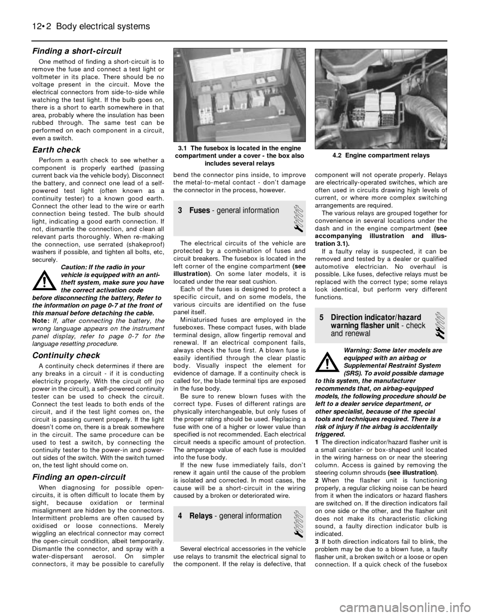
circuit breakers. The fusebox is located in the
left corner of the engine compartment (see
illustration). On some later models, it is
located under the rear seat cushion.
Each of the fuses is designed to protect a
specific circuit, and on some models, the
various circuits are identified on the fuse
panel itself.
Miniaturised fuses are employed in the
fuseboxes. These compact fuses, with blade
terminal design, allow fingertip removal and
renewal. If an electrical component fails,
always check the fuse first. A blown fuse is
easily identified through the clear plastic
body. Visually inspect the element for
evidence of damage. If a continuity check is
called for, the blade terminal tips are exposed
in the fuse body.
Be sure to renew blown fuses with the
correct type. Fuses of different ratings are
physically interchangeable, but only fuses of
the proper rating should be used. Replacing a
fuse with one of a higher or lower value than
specified is not recommended. Each electrical
circuit needs a specific amount of protection.
The amperage value of each fuse is moulded
into the fuse body.
If the new fuse immediately fails, don’t
renew it again until the cause of the problem
is isolated and corrected. In most cases, the
cause will be a short-circuit in the wiring
caused by a broken or deteriorated wire.
4 Relays- general information
1
Several electrical accessories in the vehicle
use relays to transmit the electrical signal to
the component. If the relay is defective, thatcomponent will not operate properly. Relays
are electrically-operated switches, which are
often used in circuits drawing high levels of
current, or where more complex switching
arrangements are required.
The various relays are grouped together for
convenience in several locations under the
dash and in the engine compartment (see
accompanying illustration and illus-
tration 3.1).
If a faulty relay is suspected, it can be
removed and tested by a dealer or qualified
automotive electrician. No overhaul is
possible. Like fuses, defective relays must be
replaced with the correct type; some relays
look identical, but perform very different
functions.
5 Direction indicator/hazard
warning flasher unit- check
and renewal
2
Warning: Some later models are
equipped with an airbag or
Supplemental Restraint System
(SRS). To avoid possible damage
to this system, the manufacturer
recommends that, on airbag-equipped
models, the following procedure should be
left to a dealer service department, or
other specialist, because of the special
tools and techniques required. There is a
risk of injury if the airbag is accidentally
triggered.
1The direction indicator/hazard flasher unit is
a small canister- or box-shaped unit located
in the wiring harness on or near the steering
column. Access is gained by removing the
steering column shrouds (see illustration).
2When the flasher unit is functioning
properly, a regular clicking noise can be heard
from it when the indicators or hazard flashers
are switched on. If the direction indicators fail
on one side or the other, and the flasher unit
does not make its characteristic clicking
sound, a faulty direction indicator bulb is
indicated.
3If both direction indicators fail to blink, the
problem may be due to a blown fuse, a faulty
flasher unit, a broken switch or a loose or open
connection. If a quick check of the fusebox
12•2 Body electrical systems
4.2 Engine compartment relays3.1 The fusebox is located in the engine
compartment under a cover - the box also
includes several relays
Page 171 of 228
indicates that the direction indicator and/or
hazard fuse has blown, check the wiring for a
short-circuit before fitting a new fuse.
4Make sure that the new unit is identical to
the original. Compare the old one to the new
one before fitting it.
5Refitting is the reverse of removal.
6 Steering column switches-
removal and refitting
1
Warning: Some later models are
equipped with an airbag or
Supplemental Restraint System
(SRS). To avoid possible damage
to this system, the manufacturer
recommends that, on airbag-equipped
models, the following procedure should be
left to a dealer service department, or
other specialist, because of the special
tools and techniques required. There is a
risk of injury if the airbag is accidentally
triggered.
Caution: If the radio in your
vehicle is equipped with an anti-
theft system, make sure you have
the correct activation code
before disconnecting the battery, Refer to
the information on page 0-7 at the front of
this manual before detaching the cable.
Note: If, after connecting the battery, the
wrong language appears on the instrument
panel display, refer to page 0-7 for the
language resetting procedure.
1Disconnect the battery negative cable,
remove the steering wheel (see Chapter 10)
and steering column shrouds (see Chapter 11).
Direction indicator/headlight
switch
2Where necessary, remove the switch
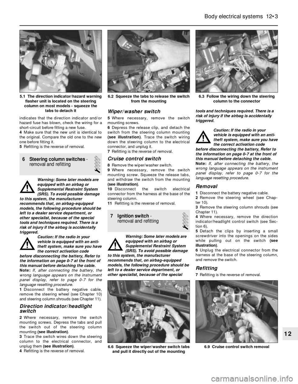
mounting screws. Depress the tabs and pull
the switch out of the steering column
mounting (see illustration).
3Trace the switch wires down the steering
column to the electrical connector, and
unplug them (see illustration).
4Refitting is the reverse of removal.
Wiper/washer switch
5Where necessary, remove the switch
mounting screws.
6Depress the release clip, and detach the
switch from the steering column mounting
(see illustration). Trace the switch wiring
down the steering column to the electrical
connector, and unplug it.
7Refitting is the reverse of removal.
Cruise control switch
8Remove the wiper/washer switch.
9Where necessary, remove the switch
mounting screw. Squeeze the release tabs,
and withdraw the switch from the mounting
(see illustration).
10Disconnect the switch electrical
connector from the harness at the base of the
steering column.
11Refitting is the reverse of removal.
7 Ignition switch-
removal and refitting
1
Warning: Some later models are
equipped with an airbag or
Supplemental Restraint System
(SRS). To avoid possible damage
to this system, the manufacturer
recommends that, on airbag-equipped
models, the following procedure should be
left to a dealer service department, or
other specialist, because of the specialtools and techniques required. There is a
risk of injury if the airbag is accidentally
triggered.
Caution: If the radio in your
vehicle is equipped with an anti-
theft system, make sure you have
the correct activation code
before disconnecting the battery, Refer to
the information on page 0-7 at the front of
this manual before detaching the cable.
Note: If, after connecting the battery, the
wrong language appears on the instrument
panel display, refer to page 0-7 for the
language resetting procedure.
Removal
1Disconnect the battery negative cable.
2Remove the steering wheel (see Chap-
ter 10).
3Remove the steering column shrouds (see
Chapter 11).
4Where necessary, remove the direction
indicator/headlight control switch (see Sec-
tion 6).
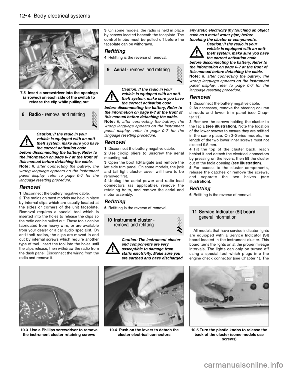
5Detach the clips by inserting a small
screwdriver into the openings on the sides
while pulling out on the switch (see
illustration).
6Unplug the electrical connector from the
harness at the base of the steering column,
and remove the switch.
Refitting
7Refitting is the reverse of removal.
Body electrical systems 12•3
6.3 Follow the wiring down the steering
column to the connector6.2 Squeeze the tabs to release the switch
from the mounting
6.9 Cruise control switch removal6.6 Squeeze the wiper/washer switch tabs
and pull it directly out of the mounting
12
5.1 The direction indicator/hazard warning
flasher unit is located on the steering
column on most models - squeeze the
tabs to detach it
Page 172 of 228
8 Radio- removal and refitting
1
Caution: If the radio in your
vehicle is equipped with an anti-
theft system, make sure you have
the correct activation code
before disconnecting the battery, Refer to
the information on page 0-7 at the front of
this manual before detaching the cable.
Note: If, after connecting the battery, the
wrong language appears on the instrument
panel display, refer to page 0-7 for the
language resetting procedure.
Removal
1Disconnect the battery negative cable.
2The radios on most models are held in place
by internal clips which are usually located at
the sides or corners of the unit faceplate.
Removal requires a special tool which is
inserted into the holes to release the clips so
the radio can be pulled out. These tools can be
fabricated from heavy wire, or are available
from your dealer or a car audio specialist. On
anti-theft radios, the clips are moved in and
out by internal screws which require another
type of tool. Insert the tool into the holes until
the clips release, then withdraw the radio from
the dash panel. Disconnect the wiring from the
radio and remove it.3On some models, the radio is held in place
by screws located beneath the faceplate. The
control knobs must be pulled off before the
faceplate can be withdrawn.
Refitting
4Refitting is the reverse of removal.
9 Aerial- removal and refitting
1
Caution: If the radio in your
vehicle is equipped with an anti-
theft system, make sure you have
the correct activation code
before disconnecting the battery, Refer to
the information on page 0-7 at the front of
this manual before detaching the cable.
Note: If, after connecting the battery, the
wrong language appears on the instrument
panel display, refer to page 0-7 for the
language resetting procedure.
Removal
1Disconnect the battery negative cable.
2Use circlip pliers to unscrew the aerial
mounting nut.
3Open the boot lid/tailgate and remove the
left side trim panel. On some models, the jack
and tail light cluster cover will have to be
removed first.
4Unplug the aerial power and radio lead
connectors (as applicable), remove the
retaining bolts, and remove the aerial and
motor assembly.
Refitting
5Refitting is the reverse of removal.
10 Instrument cluster-
removal and refitting
2
Caution: The instrument cluster
and components are very
susceptible to damage from
static electricity. Make sure you
are earthed and have dischargedany static electricity (by touching an object
such as a metal water pipe) before
touching the cluster or components.
Caution: If the radio in your
vehicle is equipped with an anti-
theft system, make sure you have
the correct activation code
before disconnecting the battery, Refer to
the information on page 0-7 at the front of
this manual before detaching the cable.
Note: If, after connecting the battery, the
wrong language appears on the instrument
panel display, refer to page 0-7 for the
language resetting procedure.
Removal
1Disconnect the battery negative cable.
2As necessary, remove the steering column
shrouds and lower trim panel (see Chap-
ter 11).
3Remove the screws holding the cluster to
the facia (see illustration). Note the location
of the lower screws to ensure they are refitted
in the same place. On 3-Series models, the
length of the two lower inner screws must not
exceed 9.5 mm.
4Tilt the top of the cluster back, reach
behind it and detach the electrical connectors
by pressing on the levers, then lift the cluster
out of the facia opening (see illustration).
5For access to the cluster components,
release the catches or remove the screws,
and separate the two halves (see
illustration).
Refitting
6Refitting is the reverse of removal.
11 Service Indicator (SI) board-
general information
All models that have service indicator lights
are equipped with a Service Indicator (SI)
board located in the instrument cluster. This
board turns the lights on at the proper mileage
intervals. The lights can only be turned off
using a special tool which plugs into the
engine check connector (see Chapter 1). The
12•4 Body electrical systems
10.5 Turn the plastic knobs to release the
back of the cluster (some models use
screws)10.4 Push on the levers to detach the
cluster electrical connectors10.3 Use a Phillips screwdriver to remove
the instrument cluster retaining screws
7.5 Insert a screwdriver into the openings
(arrowed) on each side of the switch to
release the clip while pulling out
Page 173 of 228
SI board is a self-contained computer which
includes a chip and batteries.
The rechargeable SI board nickel cadmium
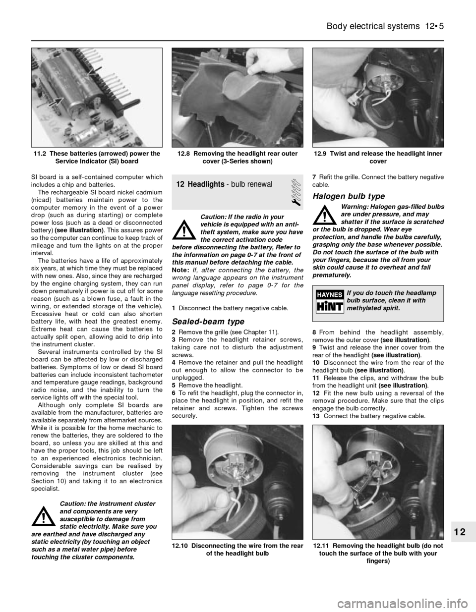
(nicad) batteries maintain power to the
computer memory in the event of a power
drop (such as during starting) or complete
power loss (such as a dead or disconnected
battery) (see illustration). This assures power
so the computer can continue to keep track of
mileage and turn the lights on at the proper
interval.
The batteries have a life of approximately
six years, at which time they must be replaced
with new ones. Also, since they are recharged
by the engine charging system, they can run
down prematurely if power is cut off for some
reason (such as a blown fuse, a fault in the
wiring, or extended storage of the vehicle).
Excessive heat or cold can also shorten
battery life, with heat the greatest enemy.
Extreme heat can cause the batteries to
actually split open, allowing acid to drip into
the instrument cluster.
Several instruments controlled by the SI
board can be affected by low or discharged
batteries. Symptoms of low or dead SI board
batteries can include inconsistent tachometer
and temperature gauge readings, background
radio noise, and the inability to turn the
service lights off with the special tool.
Although only complete SI boards are
available from the manufacturer, batteries are
available separately from aftermarket sources.
While it is possible for the home mechanic to
renew the batteries, they are soldered to the
board, so unless you are skilled at this and
have the proper tools, this job should be left
to an experienced electronics technician.
Considerable savings can be realised by
removing the instrument cluster (see
Section 10) and taking it to an electronics
specialist.
Caution: the instrument cluster
and components are very
susceptible to damage from
static electricity. Make sure you
are earthed and have discharged any
static electricity (by touching an object
such as a metal water pipe) before
touching the cluster components.12 Headlights- bulb renewal
1
Caution: If the radio in your
vehicle is equipped with an anti-
theft system, make sure you have
the correct activation code
before disconnecting the battery, Refer to
the information on page 0-7 at the front of
this manual before detaching the cable.
Note: If, after connecting the battery, the
wrong language appears on the instrument
panel display, refer to page 0-7 for the
language resetting procedure.
1Disconnect the battery negative cable.
Sealed-beam type
2Remove the grille (see Chapter 11).
3Remove the headlight retainer screws,
taking care not to disturb the adjustment
screws.
4Remove the retainer and pull the headlight
out enough to allow the connector to be
unplugged.
5Remove the headlight.
6To refit the headlight, plug the connector in,
place the headlight in position, and refit the
retainer and screws. Tighten the screws
securely.7Refit the grille. Connect the battery negative
cable.
Halogen bulb type
Warning: Halogen gas-filled bulbs
are under pressure, and may
shatter if the surface is scratched
or the bulb is dropped. Wear eye
protection, and handle the bulbs carefully,
grasping only the base whenever possible.
Do not touch the surface of the bulb with
your fingers, because the oil from your
skin could cause it to overheat and fail
prematurely.
8From behind the headlight assembly,
remove the outer cover (see illustration).
9Twist and release the inner cover from the
rear of the headlight (see illustration).
10Disconnect the wire from the rear of the
headlight bulb (see illustration).
11Release the clips, and withdraw the bulb
from the headlight unit (see illustration).
12Fit the new bulb using a reversal of the
removal procedure. Make sure that the clips
engage the bulb correctly.
13Connect the battery negative cable.
Body electrical systems 12•5
12.9 Twist and release the headlight inner
cover12.8 Removing the headlight rear outer
cover (3-Series shown)11.2 These batteries (arrowed) power the
Service Indicator (SI) board
12.11 Removing the headlight bulb (do not
touch the surface of the bulb with your
fingers)12.10 Disconnecting the wire from the rear
of the headlight bulb
12
If you do touch the headlamp
bulb surface, clean it with
methylated spirit.
Page 174 of 228
13 Headlights- adjustment
2
Note:The headlights must be aimed correctly.
If adjusted incorrectly, they could momentarily
blind the driver of an oncoming vehicle and
cause a serious accident, or seriously reduce
your ability to see the road. The headlights
should be checked for proper aim every
12 months (as is done during the MOT test),
and any time a new headlight is fitted or front-
end body work is performed. It should be
emphasised that the following procedure will
only provide a temporary setting until the
headlights can be adjusted by a properly-
equipped garage.
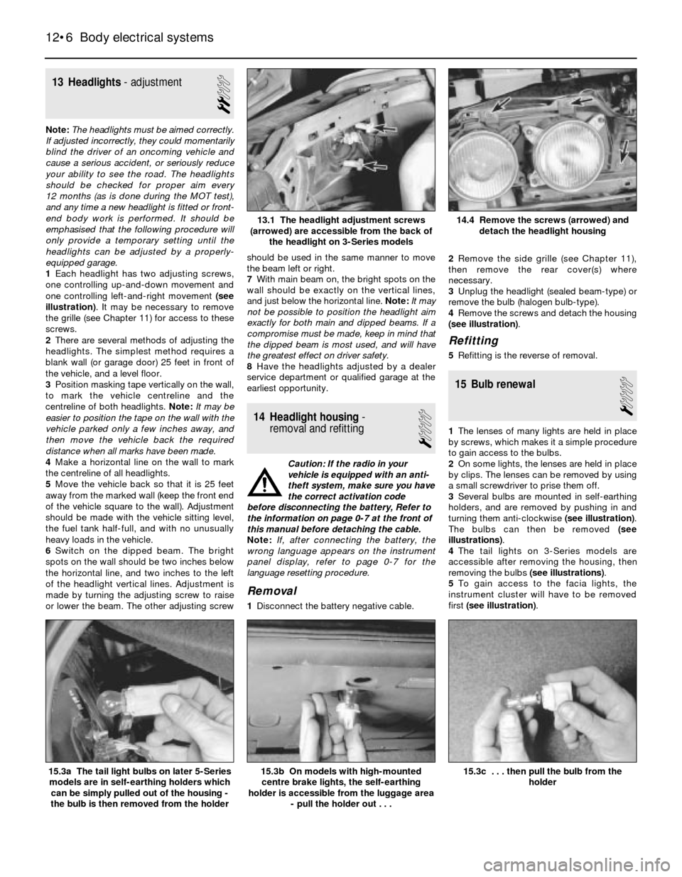
1Each headlight has two adjusting screws,
one controlling up-and-down movement and
one controlling left-and-right movement (see
illustration). It may be necessary to remove
the grille (see Chapter 11) for access to these
screws.
2There are several methods of adjusting the
headlights. The simplest method requires a
blank wall (or garage door) 25 feet in front of
the vehicle, and a level floor.
3Position masking tape vertically on the wall,
to mark the vehicle centreline and the
centreline of both headlights. Note:It may be
easier to position the tape on the wall with the
vehicle parked only a few inches away, and
then move the vehicle back the required
distance when all marks have been made.
4Make a horizontal line on the wall to mark
the centreline of all headlights.
5Move the vehicle back so that it is 25 feet
away from the marked wall (keep the front end
of the vehicle square to the wall). Adjustment
should be made with the vehicle sitting level,
the fuel tank half-full, and with no unusually
heavy loads in the vehicle.
6Switch on the dipped beam. The bright
spots on the wall should be two inches below
the horizontal line, and two inches to the left
of the headlight vertical lines. Adjustment is
made by turning the adjusting screw to raise
or lower the beam. The other adjusting screwshould be used in the same manner to move
the beam left or right.
7With main beam on, the bright spots on the
wall should be exactly on the vertical lines,
and just below the horizontal line. Note:It may
not be possible to position the headlight aim
exactly for both main and dipped beams. If a
compromise must be made, keep in mind that
the dipped beam is most used, and will have
the greatest effect on driver safety.
8Have the headlights adjusted by a dealer
service department or qualified garage at the
earliest opportunity.
14 Headlight housing-
removal and refitting
1
Caution: If the radio in your
vehicle is equipped with an anti-
theft system, make sure you have
the correct activation code
before disconnecting the battery, Refer to
the information on page 0-7 at the front of
this manual before detaching the cable.
Note: If, after connecting the battery, the
wrong language appears on the instrument
panel display, refer to page 0-7 for the
language resetting procedure.
Removal
1Disconnect the battery negative cable.2Remove the side grille (see Chapter 11),
then remove the rear cover(s) where
necessary.
3Unplug the headlight (sealed beam-type) or
remove the bulb (halogen bulb-type).
4Remove the screws and detach the housing
(see illustration).
Refitting
5Refitting is the reverse of removal.
15 Bulb renewal
1
1The lenses of many lights are held in place
by screws, which makes it a simple procedure
to gain access to the bulbs.
2On some lights, the lenses are held in place
by clips. The lenses can be removed by using
a small screwdriver to prise them off.
3Several bulbs are mounted in self-earthing
holders, and are removed by pushing in and
turning them anti-clockwise (see illustration).
The bulbs can then be removed (see
illustrations).
4The tail lights on 3-Series models are
accessible after removing the housing, then
removing the bulbs (see illustrations).
5To gain access to the facia lights, the
instrument cluster will have to be removed
first (see illustration).
12•6 Body electrical systems
15.3c . . . then pull the bulb from the
holder15.3b On models with high-mounted
centre brake lights, the self-earthing
holder is accessible from the luggage area
- pull the holder out . . .15.3a The tail light bulbs on later 5-Series
models are in self-earthing holders which
can be simply pulled out of the housing -
the bulb is then removed from the holder
14.4 Remove the screws (arrowed) and
detach the headlight housing13.1 The headlight adjustment screws
(arrowed) are accessible from the back of
the headlight on 3-Series models
Page 175 of 228
16 Windscreen/tailgate wiper
motor- removal and refitting
2
Caution: If the radio in your
vehicle is equipped with an anti-
theft system, make sure you have
the correct activation code
before disconnecting the battery, Refer to
the information on page 0-7 at the front of
this manual before detaching the cable.
Note: If, after connecting the battery, the
wrong language appears on the instrument
panel display, refer to page 0-7 for the
language resetting procedure.
1Disconnect the battery negative cable.
Windscreen wiper motor
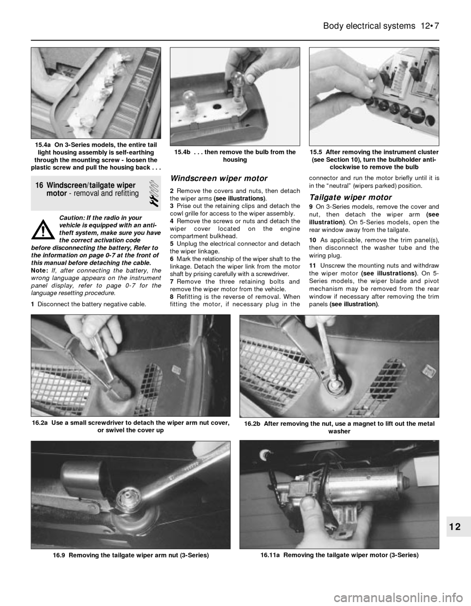
2Remove the covers and nuts, then detach
the wiper arms (see illustrations).
3Prise out the retaining clips and detach the
cowl grille for access to the wiper assembly.
4Remove the screws or nuts and detach the
wiper cover located on the engine
compartment bulkhead.
5Unplug the electrical connector and detach
the wiper linkage.
6Mark the relationship of the wiper shaft to the
linkage. Detach the wiper link from the motor
shaft by prising carefully with a screwdriver.
7Remove the three retaining bolts and
remove the wiper motor from the vehicle.
8Refitting is the reverse of removal. When
fitting the motor, if necessary plug in theconnector and run the motor briefly until it is
in the “neutral” (wipers parked) position.Tailgate wiper motor
9On 3-Series models, remove the cover and
nut, then detach the wiper arm (see
illustration). On 5-Series models, open the
rear window away from the tailgate.
10As applicable, remove the trim panel(s),
then disconnect the washer tube and the
wiring plug.
11Unscrew the mounting nuts and withdraw
the wiper motor (see illustrations). On 5-
Series models, the wiper blade and pivot
mechanism may be removed from the rear
window if necessary after removing the trim
panels (see illustration).
Body electrical systems 12•7
15.5 After removing the instrument cluster
(see Section 10), turn the bulbholder anti-
clockwise to remove the bulb15.4b . . . then remove the bulb from the
housing15.4a On 3-Series models, the entire tail
light housing assembly is self-earthing
through the mounting screw - loosen the
plastic screw and pull the housing back . . .
16.11a Removing the tailgate wiper motor (3-Series)
16.2b After removing the nut, use a magnet to lift out the metal
washer16.2a Use a small screwdriver to detach the wiper arm nut cover,
or swivel the cover up
16.9 Removing the tailgate wiper arm nut (3-Series)
12
Page 222 of 228
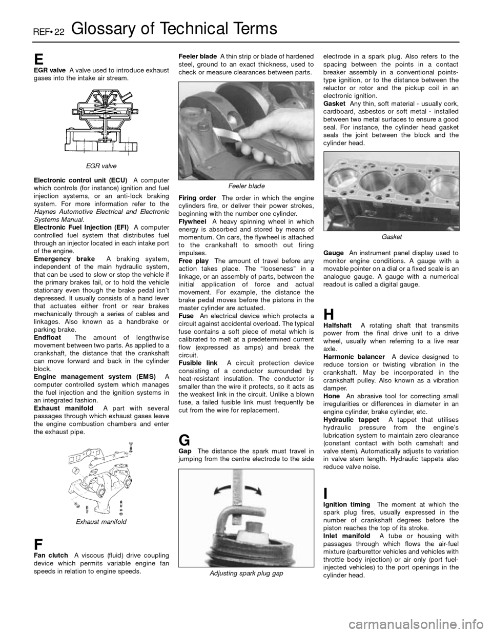
REF•22Glossary of Technical Terms
EEGR valveA valve used to introduce exhaust
gases into the intake air stream.
Electronic control unit (ECU)A computer
which controls (for instance) ignition and fuel
injection systems, or an anti-lock braking
system. For more information refer to the
Haynes Automotive Electrical and Electronic
Systems Manual.
Electronic Fuel Injection (EFI)A computer
controlled fuel system that distributes fuel
through an injector located in each intake port
of the engine.
Emergency brakeA braking system,
independent of the main hydraulic system,
that can be used to slow or stop the vehicle if
the primary brakes fail, or to hold the vehicle
stationary even though the brake pedal isn’t
depressed. It usually consists of a hand lever
that actuates either front or rear brakes
mechanically through a series of cables and
linkages. Also known as a handbrake or
parking brake.
EndfloatThe amount of lengthwise
movement between two parts. As applied to a
crankshaft, the distance that the crankshaft
can move forward and back in the cylinder
block.
Engine management system (EMS)A
computer controlled system which manages
the fuel injection and the ignition systems in
an integrated fashion.
Exhaust manifoldA part with several
passages through which exhaust gases leave
the engine combustion chambers and enter
the exhaust pipe.
FFan clutchA viscous (fluid) drive coupling
device which permits variable engine fan
speeds in relation to engine speeds.Feeler bladeA thin strip or blade of hardened
steel, ground to an exact thickness, used to
check or measure clearances between parts.
Firing orderThe order in which the engine
cylinders fire, or deliver their power strokes,
beginning with the number one cylinder.
Flywheel A heavy spinning wheel in which
energy is absorbed and stored by means of
momentum. On cars, the flywheel is attached
to the crankshaft to smooth out firing
impulses.
Free playThe amount of travel before any
action takes place. The “looseness” in a
linkage, or an assembly of parts, between the
initial application of force and actual
movement. For example, the distance the
brake pedal moves before the pistons in the
master cylinder are actuated.
FuseAn electrical device which protects a
circuit against accidental overload. The typical
fuse contains a soft piece of metal which is
calibrated to melt at a predetermined current
flow (expressed as amps) and break the
circuit.
Fusible linkA circuit protection device
consisting of a conductor surrounded by
heat-resistant insulation. The conductor is
smaller than the wire it protects, so it acts as
the weakest link in the circuit. Unlike a blown
fuse, a failed fusible link must frequently be
cut from the wire for replacement.
GGapThe distance the spark must travel in
jumping from the centre electrode to the sideelectrode in a spark plug. Also refers to the
spacing between the points in a contact
breaker assembly in a conventional points-
type ignition, or to the distance between the
reluctor or rotor and the pickup coil in an
electronic ignition.
GasketAny thin, soft material - usually cork,
cardboard, asbestos or soft metal - installed
between two metal surfaces to ensure a good
seal. For instance, the cylinder head gasket
seals the joint between the block and the
cylinder head.
GaugeAn instrument panel display used to
monitor engine conditions. A gauge with a
movable pointer on a dial or a fixed scale is an
analogue gauge. A gauge with a numerical
readout is called a digital gauge.
HHalfshaftA rotating shaft that transmits
power from the final drive unit to a drive
wheel, usually when referring to a live rear
axle.
Harmonic balancerA device designed to
reduce torsion or twisting vibration in the
crankshaft. May be incorporated in the
crankshaft pulley. Also known as a vibration
damper.
HoneAn abrasive tool for correcting small
irregularities or differences in diameter in an
engine cylinder, brake cylinder, etc.
Hydraulic tappetA tappet that utilises
hydraulic pressure from the engine’s
lubrication system to maintain zero clearance
(constant contact with both camshaft and
valve stem). Automatically adjusts to variation
in valve stem length. Hydraulic tappets also
reduce valve noise.
IIgnition timingThe moment at which the
spark plug fires, usually expressed in the
number of crankshaft degrees before the
piston reaches the top of its stroke.
Inlet manifoldA tube or housing with
passages through which flows the air-fuel
mixture (carburettor vehicles and vehicles with
throttle body injection) or air only (port fuel-
injected vehicles) to the port openings in the
cylinder head.
Exhaust manifold
Feeler blade
Adjusting spark plug gap
Gasket
EGR valve
Page 226 of 228

REF•26Index
E
Earth check - 12•2
Electric fan - 3•4
Electric shock - 0•5
Electric windows - 12•9
Electrical equipment - REF•2
Electrical system fault finding - 12•1
Electronic control system - 4•3, 4•14
Electronic control unit (ECU) - 6•1
Engine fault finding - REF•10
Engine tune-up - 1•7
Engine electrical systems- 5•1et seq
Engine electrical systems fault finding -
REF•11
Engine management and emission control
systems- 6•1et seq
Engine oil - 1•3, 1•7, 1•11
Environmental considerations - REF•8
Evaporative emissions control (EVAP)
system - 1•26, 6•5
Evaporator - 3•10
Exhaust emission checks - REF•4
Exhaust manifold - 2A•6
Exhaust system - 1•21, 4•20, REF•3
F
Fan - 3•4, 3•5
Fault finding- REF•9et seq
Fault finding - automatic transmission -
7B•2, REF•13
Fault finding - braking system - REF•14
Fault finding - clutch - REF•12
Fault finding - cooling system - REF•12
Fault finding - electrical system - 12•1,
REF•11
Fault finding - engine - REF•10
Fault finding - fuel system - 4•21, REF•12
Fault finding - manual transmission -
REF•13
Fault finding - suspension and steering -
REF•15
Filling - 11•3
Final drive - 8•2, 8•10, 8•11
Final drive oil - 1•3, 1•19, 1•26
Fire - 0•5
Flexible coupling - 8•7
Fluid level checks - 1•7
Fluid seals - 7B•5
Flywheel - 2A•18
Fuel and exhaust systems- 1•20, 4•1et
seq,REF•4
Fuel system fault finding - REF•12
Fuel filter - 1•25
Fuel hoses - 1•14
Fuel injection system - 4•3, 4•14
Fuel injection system - fault finding - 4•21
Fuel injectors - 4•18
Fuel level sender unit - 4•5, 4•6
Fuel lines and fittings - 4•7
Fuel pressure - 4•3
Fuel pressure regulator - 4•16
Fuel pump - 4•3, 4•4, 4•5
Fuel tank - 4•7, 4•8
Fume or gas intoxication - 0•5
Fuses - 12•2
G
Gaiters - 1•22, 8•9, 10•13
Gashes in bodywork - 11•2
Gaskets - REF•8
Gear lever - 7A•1
Gearbox - SeeManual transmission
Gearbox oil - 1•3, 1•19, 1•25
General engine overhaul procedures-
2B•1et seq
Glass - 11•4, 11•8
Glossary of technical terms - REF•20
Grille - 11•4
H
Handbrake - 1•23, 9•2, 9•12, REF•1
Handbrake fault - REF•14
Handles - 11•8
Hazard warning flasher - 12•2
HC emissions - REF•4
Headlights - 12•3, 12•5, 12•6
Heated rear window - 12•8
Heater - 3•2, 3•7, 3•8
Hinges - 11•4
HT leads - 1•18
Hubs - 10•8, 10•11, REF•3
Hydraulic servo - 9•11
Hydraulic tappets - 2B•11
Hydrofluoric acid - 0•5
I
Idle air stabiliser valve - 4•18
Idle speed adjustment - 1•15
Ignition coil - 5•5
Ignition control unit - 5•6, 5•7
Ignition sensors - 5•8
Ignition switch - 12•3
Ignition system - 5•3
Ignition timing - 5•4
Ignition timing sensors - 6•4
Impulse generator - 5•6, 5•7
In-car engine repair procedures- 2A•1et
seq
Indicators - 12•2, 12•3
Information sensors - 6•2
Injectors - 4•18
Input shaft - 7A•2
Instrument cluster - 12•4
Instrument panel language display - 0•7
Intake manifold - 2A•4
Intermediate shaft - 2A•12, 2B•14, 2B•19
Introduction to the BMW 3- and 5-Series -
0•4
J
Jacking - 0•8
Joint mating faces - REF•8
Jump starting - 0•9
K
Kickdown cable - 7B•3
L
L-Jetronic fuel injection system - 4•14,
4•19
Language display - 0•7
Latch - 11•8
Leaks - 0•10, 7B•3, REF•12, REF•13
Locknuts, locktabs and washers - REF•8
Locks - 11•4, 11•8
Lubricants - REF•18
M
Main bearings - 2B•17, 2B•19
Manifolds - 2A•4, 2A•6
Manual transmission- 7A•1et seq
Manual transmission fault finding - REF•13
Manual transmission oil - 1•3, 1•19, 1•25
Master cylinder - 8•3, 9•9
Mechanical fan - 3•4, 3•5
Mirrors - 11•8, REF•1
Misfire - REF•11
Mixture - REF•4
MOT test checks- REF•1 et seq
Motronic engine management system -
6•1
Motronic fuel injection system - 4•14, 4•19
Mountings - 2A•19, 7A•3
O
Oil - differential - 1•19, 1•26
Oil - engine - 1•3, 1•7, 1•11
Oil - final drive - 1•3
Oil - manual transmission - 1•3, 1•19, 1•25
Oil filter - 1•11, 1•12
Oil pump - 2A•16
Oil seals - 2A•12, 2A•13, 2A•19, 2B•20,
7A•2, 7B•5, 8•10, 8•12, REF•8
Open-circuit - 12•2
Output shaft - 7A•2, 7B•5
Overcooling - REF•12
Overheating - REF•12
Oxygen sensor - 6•2
P
Pads - 9•2, 9•3
Pedals - 8•3, 9•13
Pinion oil - 8•12
Pinking - REF•11
Piston rings - 2B•18
Pistons - 2B•12, 2B•16, 2B•21
Plastic components - 11•3
Poisonous or irritant substances - 0•5
Position sensors - 5•8
Positive crankcase ventilation (PCV)
system - 6•4
Power steering - 1•14, 10•15, 10•16
Power steering fluid - 1•12
Propeller shaft - 8•2, 8•6, 8•8
Pulse sensor - 5•8
Purge valve - 6•5