service BMW 3 SERIES 1983 E30 Repair Manual
[x] Cancel search | Manufacturer: BMW, Model Year: 1983, Model line: 3 SERIES, Model: BMW 3 SERIES 1983 E30Pages: 228, PDF Size: 7.04 MB
Page 172 of 228
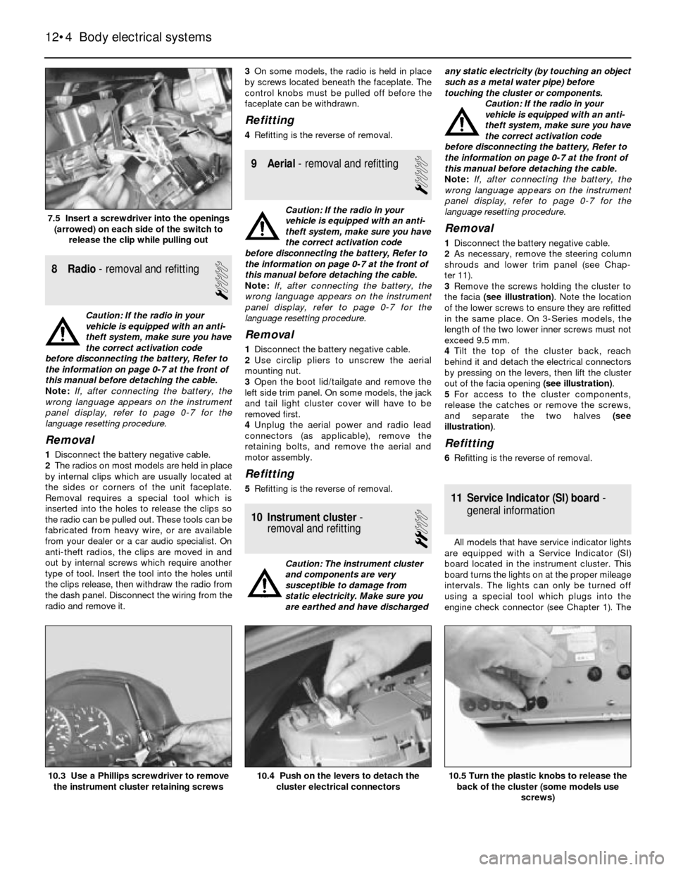
8 Radio- removal and refitting
1
Caution: If the radio in your
vehicle is equipped with an anti-
theft system, make sure you have
the correct activation code
before disconnecting the battery, Refer to
the information on page 0-7 at the front of
this manual before detaching the cable.
Note: If, after connecting the battery, the
wrong language appears on the instrument
panel display, refer to page 0-7 for the
language resetting procedure.
Removal
1Disconnect the battery negative cable.
2The radios on most models are held in place
by internal clips which are usually located at
the sides or corners of the unit faceplate.
Removal requires a special tool which is
inserted into the holes to release the clips so
the radio can be pulled out. These tools can be
fabricated from heavy wire, or are available
from your dealer or a car audio specialist. On
anti-theft radios, the clips are moved in and
out by internal screws which require another
type of tool. Insert the tool into the holes until
the clips release, then withdraw the radio from
the dash panel. Disconnect the wiring from the
radio and remove it.3On some models, the radio is held in place
by screws located beneath the faceplate. The
control knobs must be pulled off before the
faceplate can be withdrawn.
Refitting
4Refitting is the reverse of removal.
9 Aerial- removal and refitting
1
Caution: If the radio in your
vehicle is equipped with an anti-
theft system, make sure you have
the correct activation code
before disconnecting the battery, Refer to
the information on page 0-7 at the front of
this manual before detaching the cable.
Note: If, after connecting the battery, the
wrong language appears on the instrument
panel display, refer to page 0-7 for the
language resetting procedure.
Removal
1Disconnect the battery negative cable.
2Use circlip pliers to unscrew the aerial
mounting nut.
3Open the boot lid/tailgate and remove the
left side trim panel. On some models, the jack
and tail light cluster cover will have to be
removed first.
4Unplug the aerial power and radio lead
connectors (as applicable), remove the
retaining bolts, and remove the aerial and
motor assembly.
Refitting
5Refitting is the reverse of removal.
10 Instrument cluster-
removal and refitting
2
Caution: The instrument cluster
and components are very
susceptible to damage from
static electricity. Make sure you
are earthed and have dischargedany static electricity (by touching an object
such as a metal water pipe) before
touching the cluster or components.
Caution: If the radio in your
vehicle is equipped with an anti-
theft system, make sure you have
the correct activation code
before disconnecting the battery, Refer to
the information on page 0-7 at the front of
this manual before detaching the cable.
Note: If, after connecting the battery, the
wrong language appears on the instrument
panel display, refer to page 0-7 for the
language resetting procedure.
Removal
1Disconnect the battery negative cable.
2As necessary, remove the steering column
shrouds and lower trim panel (see Chap-
ter 11).
3Remove the screws holding the cluster to
the facia (see illustration). Note the location
of the lower screws to ensure they are refitted
in the same place. On 3-Series models, the
length of the two lower inner screws must not
exceed 9.5 mm.
4Tilt the top of the cluster back, reach
behind it and detach the electrical connectors
by pressing on the levers, then lift the cluster
out of the facia opening (see illustration).
5For access to the cluster components,
release the catches or remove the screws,
and separate the two halves (see
illustration).
Refitting
6Refitting is the reverse of removal.
11 Service Indicator (SI) board-
general information
All models that have service indicator lights
are equipped with a Service Indicator (SI)
board located in the instrument cluster. This
board turns the lights on at the proper mileage
intervals. The lights can only be turned off
using a special tool which plugs into the
engine check connector (see Chapter 1). The
12•4 Body electrical systems
10.5 Turn the plastic knobs to release the
back of the cluster (some models use
screws)10.4 Push on the levers to detach the
cluster electrical connectors10.3 Use a Phillips screwdriver to remove
the instrument cluster retaining screws
7.5 Insert a screwdriver into the openings
(arrowed) on each side of the switch to
release the clip while pulling out
Page 173 of 228
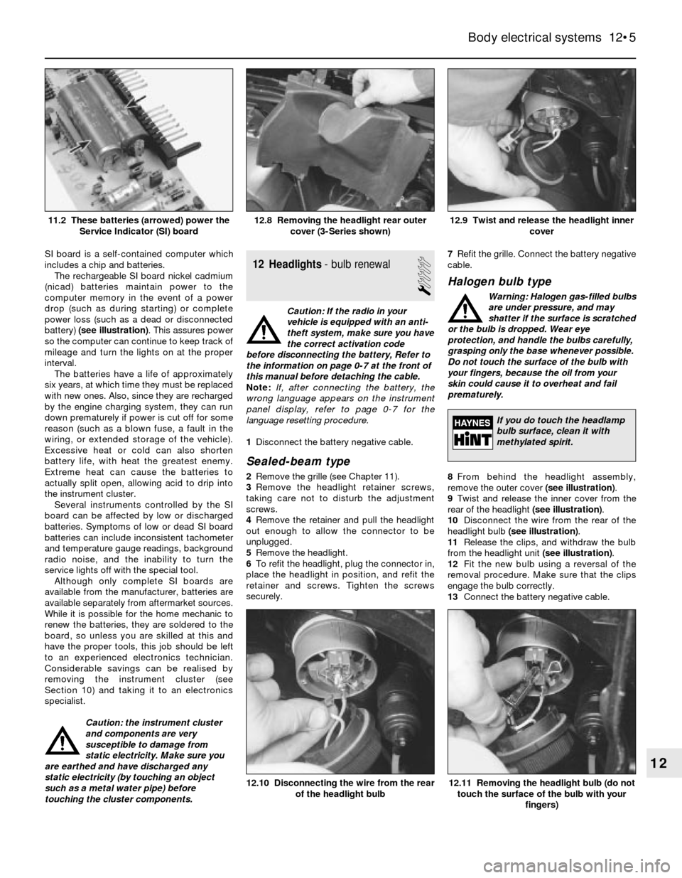
SI board is a self-contained computer which
includes a chip and batteries.
The rechargeable SI board nickel cadmium
(nicad) batteries maintain power to the
computer memory in the event of a power
drop (such as during starting) or complete
power loss (such as a dead or disconnected
battery) (see illustration). This assures power
so the computer can continue to keep track of
mileage and turn the lights on at the proper
interval.
The batteries have a life of approximately
six years, at which time they must be replaced
with new ones. Also, since they are recharged
by the engine charging system, they can run
down prematurely if power is cut off for some
reason (such as a blown fuse, a fault in the
wiring, or extended storage of the vehicle).
Excessive heat or cold can also shorten
battery life, with heat the greatest enemy.
Extreme heat can cause the batteries to
actually split open, allowing acid to drip into
the instrument cluster.
Several instruments controlled by the SI
board can be affected by low or discharged
batteries. Symptoms of low or dead SI board
batteries can include inconsistent tachometer
and temperature gauge readings, background
radio noise, and the inability to turn the
service lights off with the special tool.
Although only complete SI boards are
available from the manufacturer, batteries are
available separately from aftermarket sources.
While it is possible for the home mechanic to
renew the batteries, they are soldered to the
board, so unless you are skilled at this and
have the proper tools, this job should be left
to an experienced electronics technician.
Considerable savings can be realised by
removing the instrument cluster (see
Section 10) and taking it to an electronics
specialist.
Caution: the instrument cluster
and components are very
susceptible to damage from
static electricity. Make sure you
are earthed and have discharged any
static electricity (by touching an object
such as a metal water pipe) before
touching the cluster components.12 Headlights- bulb renewal
1
Caution: If the radio in your
vehicle is equipped with an anti-
theft system, make sure you have
the correct activation code
before disconnecting the battery, Refer to
the information on page 0-7 at the front of
this manual before detaching the cable.
Note: If, after connecting the battery, the
wrong language appears on the instrument
panel display, refer to page 0-7 for the
language resetting procedure.
1Disconnect the battery negative cable.
Sealed-beam type
2Remove the grille (see Chapter 11).
3Remove the headlight retainer screws,
taking care not to disturb the adjustment
screws.
4Remove the retainer and pull the headlight
out enough to allow the connector to be
unplugged.
5Remove the headlight.
6To refit the headlight, plug the connector in,
place the headlight in position, and refit the
retainer and screws. Tighten the screws
securely.7Refit the grille. Connect the battery negative
cable.
Halogen bulb type
Warning: Halogen gas-filled bulbs
are under pressure, and may
shatter if the surface is scratched
or the bulb is dropped. Wear eye
protection, and handle the bulbs carefully,
grasping only the base whenever possible.
Do not touch the surface of the bulb with
your fingers, because the oil from your
skin could cause it to overheat and fail
prematurely.
8From behind the headlight assembly,
remove the outer cover (see illustration).
9Twist and release the inner cover from the
rear of the headlight (see illustration).
10Disconnect the wire from the rear of the
headlight bulb (see illustration).
11Release the clips, and withdraw the bulb
from the headlight unit (see illustration).
12Fit the new bulb using a reversal of the
removal procedure. Make sure that the clips
engage the bulb correctly.
13Connect the battery negative cable.
Body electrical systems 12•5
12.9 Twist and release the headlight inner
cover12.8 Removing the headlight rear outer
cover (3-Series shown)11.2 These batteries (arrowed) power the
Service Indicator (SI) board
12.11 Removing the headlight bulb (do not
touch the surface of the bulb with your
fingers)12.10 Disconnecting the wire from the rear
of the headlight bulb
12
If you do touch the headlamp
bulb surface, clean it with
methylated spirit.
Page 174 of 228
13 Headlights- adjustment
2
Note:The headlights must be aimed correctly.
If adjusted incorrectly, they could momentarily
blind the driver of an oncoming vehicle and
cause a serious accident, or seriously reduce
your ability to see the road. The headlights
should be checked for proper aim every
12 months (as is done during the MOT test),
and any time a new headlight is fitted or front-
end body work is performed. It should be
emphasised that the following procedure will
only provide a temporary setting until the
headlights can be adjusted by a properly-
equipped garage.
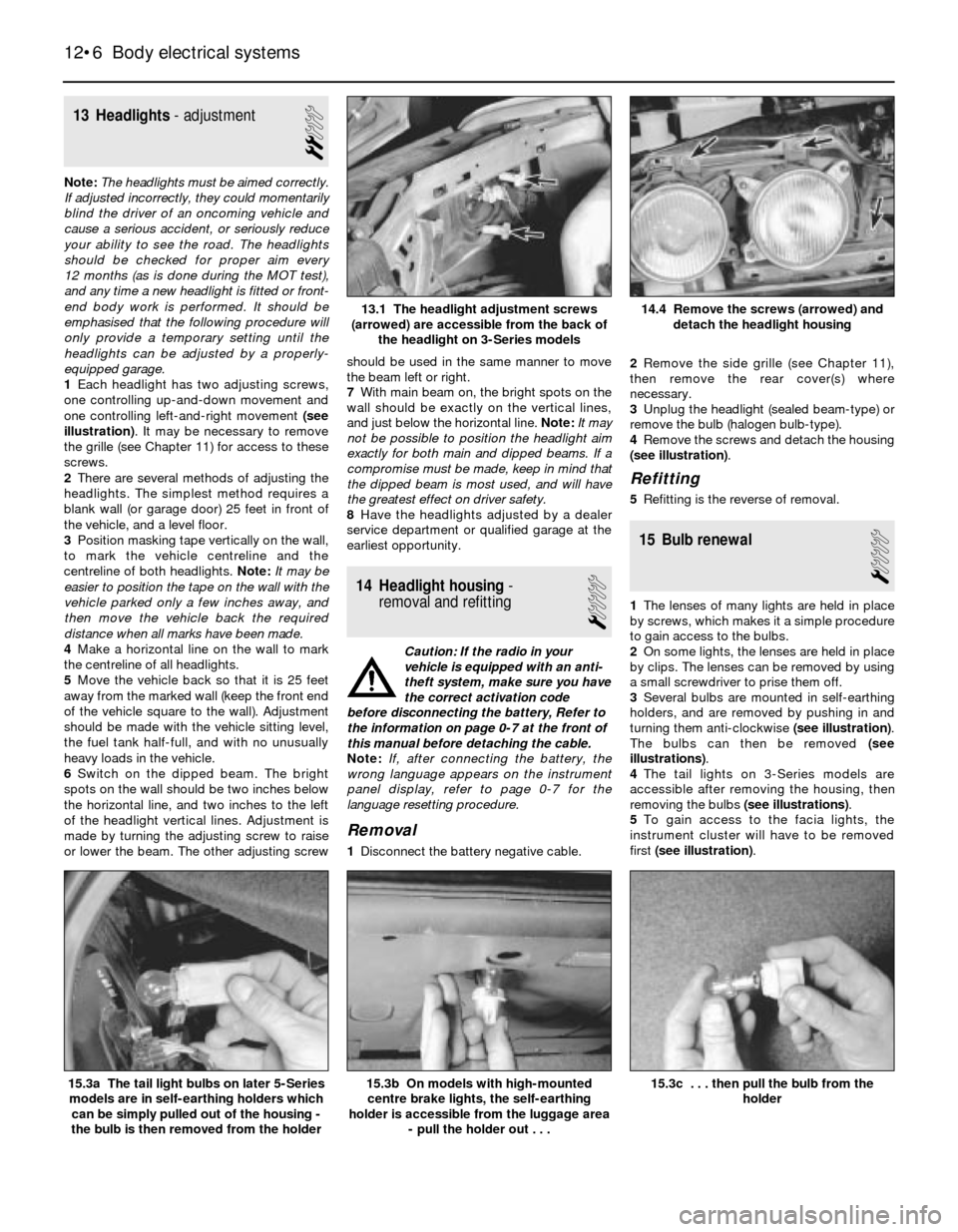
1Each headlight has two adjusting screws,
one controlling up-and-down movement and
one controlling left-and-right movement (see
illustration). It may be necessary to remove
the grille (see Chapter 11) for access to these
screws.
2There are several methods of adjusting the
headlights. The simplest method requires a
blank wall (or garage door) 25 feet in front of
the vehicle, and a level floor.
3Position masking tape vertically on the wall,
to mark the vehicle centreline and the
centreline of both headlights. Note:It may be
easier to position the tape on the wall with the
vehicle parked only a few inches away, and
then move the vehicle back the required
distance when all marks have been made.
4Make a horizontal line on the wall to mark
the centreline of all headlights.
5Move the vehicle back so that it is 25 feet
away from the marked wall (keep the front end
of the vehicle square to the wall). Adjustment
should be made with the vehicle sitting level,
the fuel tank half-full, and with no unusually
heavy loads in the vehicle.
6Switch on the dipped beam. The bright
spots on the wall should be two inches below
the horizontal line, and two inches to the left
of the headlight vertical lines. Adjustment is
made by turning the adjusting screw to raise
or lower the beam. The other adjusting screwshould be used in the same manner to move
the beam left or right.
7With main beam on, the bright spots on the
wall should be exactly on the vertical lines,
and just below the horizontal line. Note:It may
not be possible to position the headlight aim
exactly for both main and dipped beams. If a
compromise must be made, keep in mind that
the dipped beam is most used, and will have
the greatest effect on driver safety.
8Have the headlights adjusted by a dealer
service department or qualified garage at the
earliest opportunity.
14 Headlight housing-
removal and refitting
1
Caution: If the radio in your
vehicle is equipped with an anti-
theft system, make sure you have
the correct activation code
before disconnecting the battery, Refer to
the information on page 0-7 at the front of
this manual before detaching the cable.
Note: If, after connecting the battery, the
wrong language appears on the instrument
panel display, refer to page 0-7 for the
language resetting procedure.
Removal
1Disconnect the battery negative cable.2Remove the side grille (see Chapter 11),
then remove the rear cover(s) where
necessary.
3Unplug the headlight (sealed beam-type) or
remove the bulb (halogen bulb-type).
4Remove the screws and detach the housing
(see illustration).
Refitting
5Refitting is the reverse of removal.
15 Bulb renewal
1
1The lenses of many lights are held in place
by screws, which makes it a simple procedure
to gain access to the bulbs.
2On some lights, the lenses are held in place
by clips. The lenses can be removed by using
a small screwdriver to prise them off.
3Several bulbs are mounted in self-earthing
holders, and are removed by pushing in and
turning them anti-clockwise (see illustration).
The bulbs can then be removed (see
illustrations).
4The tail lights on 3-Series models are
accessible after removing the housing, then
removing the bulbs (see illustrations).
5To gain access to the facia lights, the
instrument cluster will have to be removed
first (see illustration).
12•6 Body electrical systems
15.3c . . . then pull the bulb from the
holder15.3b On models with high-mounted
centre brake lights, the self-earthing
holder is accessible from the luggage area
- pull the holder out . . .15.3a The tail light bulbs on later 5-Series
models are in self-earthing holders which
can be simply pulled out of the housing -
the bulb is then removed from the holder
14.4 Remove the screws (arrowed) and
detach the headlight housing13.1 The headlight adjustment screws
(arrowed) are accessible from the back of
the headlight on 3-Series models
Page 176 of 228
12Refitting is a reversal of removal. When
fitting the motor, if necessary plug in the
connector and run the motor briefly until it is
in the “neutral” (wiper parked) position.
17 Heated rear window-
check and repair
2
1The heated rear window consists of a
number of horizontal elements on the glass
surface.
2Small breaks in the element can be repaired
without removing the rear window.
Check
3Switch on the ignition and the heated rear
window.
4Place the positive lead of a voltmeter to the
heater element nearest to the incoming power
source.
5Wrap a piece of aluminium foil around the
negative lead of the voltmeter on the positive
side of the suspected broken element, and
slide it slowly towards the negative side.
Watch the voltmeter needle - when it moves
from zero, you have located the break.
Repair
6Repair the break in the line using a repair kit
recommended specifically for this purpose,
such as BMW repair kit No. 81 22 9 (or
equivalent). Included in this kit is plastic
conductive epoxy. The following paragraphs
give general instructions for this type of repair;
follow the instructions supplied with the repair
kit if they are different.
7Prior to repairing a break, switch off the
circuit and allow it to cool down for a few
minutes.
8Lightly buff the element area with fine steel
wool, then clean it thoroughly.
9Use masking tape to mask off the area of
repair, leaving a slit to which the epoxy can be
applied.
10Mix the epoxy thoroughly, according to
the instructions on the package.
11Apply the epoxy material to the slit in the
masking tape, overlapping the undamaged
area about 20 mm on each end.12Allow the repair to cure for 24 hours
before removing the tape and using the
heated rear window.
18 Supplemental Restraint
System (SRS)- general
information
Later models are equipped with a
Supplemental Restraint System (SRS),
incorporating an airbag. This system is
designed to protect the driver from serious
injury in the event of a head-on or frontal
collision. It consists of an airbag module in the
centre of the steering wheel, two crash
sensors mounted on the front inner wing
panels, and a crash safety switch located
inside the passenger compartment.
The airbag module contains a housing
incorporating the airbag and the inflator units.
The inflator assembly is mounted on the back
of the housing over a hole through which gas
is expelled, inflating the bag almost instanta-
neously when an electrical signal is sent from
the system. This signal is carried by a wire
which is specially wound with several turns,
so the signal will be transmitted regardless of
the steering wheel position.
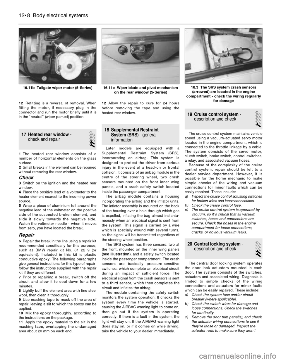
The SRS system has three sensors: two at
the front, mounted on the inner wing panels
(see illustration), and a safety switch located
inside the passenger compartment. The crash
sensors are basically pressure-sensitive
switches, which complete an electrical circuit
during an impact of sufficient force. The
electrical signal from the crash sensors is sent
to a third sensor, which then completes the
circuit and inflates the airbag.
The module containing the safety switch
monitors the system operation. It checks the
system every time the vehicle is started,
causing the AIRBAG warning light to come on,
then go out if the system is operating
correctly. If there is a fault in the system, the
light will stay on. If the AIRBAG warning light
does stay on, or if it comes on while driving,
take the vehicle to your dealer immediately.
19 Cruise control system-
description and check
1
The cruise control system maintains vehicle
speed using a vacuum-actuated servo motor
located in the engine compartment, which is
connected to the throttle linkage by a cable.
The system consists of the servo motor,
clutch switch, brake switch, control switches,
a relay, and associated vacuum hoses.
Because of the complexity of the cruise
control system, repair should be left to a
dealer service department. However, it is
possible for the home mechanic to make
simple checks of the wiring and vacuum
connections for minor faults which can be
easily repaired. These include:
a) Inspect the cruise control actuating switches
for broken wires and loose connections.
b) Check the cruise control fuse.
c) The cruise control system is operated by
vacuum, so it’s critical that all vacuum
switches, hoses and connections are
secure. Check the hoses in the engine
compartment for loose connections,
cracks, or obvious vacuum leaks.
20 Central locking system-
description and check
2
The central door locking system operates
the door lock actuators mounted in each
door. The system consists of the switches,
actuators and associated wiring. Diagnosis is
limited to simple checks of the wiring
connections and actuators for minor faults
which can be easily repaired. These include:
a) Check the system fuse and/or circuit
breaker (where applicable).
b) Check the switch wires for damage and
loose connections. Check the switches
for continuity.
c) Remove the door trim panel(s), and check
the actuator wiring connections to see if
they’re loose or damaged. Inspect the
actuator rods to make sure they aren’t
12•8 Body electrical systems
18.3 The SRS system crash sensors
(arrowed) are located in the engine
compartment - check the wiring regularly
for damage16.11b Tailgate wiper motor (5-Series)16.11c Wiper blade and pivot mechanism
on the rear window (5-Series)
Page 208 of 228
REF•7
REF
Tools and Working Facilities
MImpact screwdriver
MMicrometer and/or vernier calipers (see
illustrations)
MDial gauge (see illustration)
MUniversal electrical multi-meter
MCylinder compression gauge
(see illustration)
MClutch plate alignment set (see illustration)
MBrake shoe steady spring cup removal tool
(see illustration)
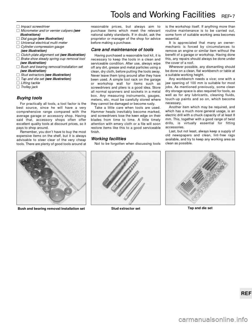
MBush and bearing removal/installation set
(see illustration)
MStud extractors (see illustration)
MTap and die set (see illustration)
MLifting tackle
MTrolley jack
Buying tools
For practically all tools, a tool factor is the
best source, since he will have a very
comprehensive range compared with the
average garage or accessory shop. Having
said that, accessory shops often offer
excellent quality tools at discount prices, so it
pays to shop around.
Remember, you don’t have to buy the most
expensive items on the shelf, but it is always
advisable to steer clear of the very cheap
tools. There are plenty of good tools around atreasonable prices, but always aim to
purchase items which meet the relevant
national safety standards. If in doubt, ask the
proprietor or manager of the shop for advice
before making a purchase.
Care and maintenance of tools
Having purchased a reasonable tool kit, it is
necessary to keep the tools in a clean and
serviceable condition. After use, always wipe
off any dirt, grease and metal particles using a
clean, dry cloth, before putting the tools away.
Never leave them lying around after they have
been used. A simple tool rack on the garage
or workshop wall for items such as
screwdrivers and pliers is a good idea. Store
all normal spanners and sockets in a metal
box. Any measuring instruments, gauges,
meters, etc, must be carefully stored where
they cannot be damaged or become rusty.
Take a little care when tools are used.
Hammer heads inevitably become marked,
and screwdrivers lose the keen edge on their
blades from time to time. A little timely
attention with emery cloth or a file will soon
restore items like this to a good serviceable
finish.
Working facilities
Not to be forgotten when discussing toolsis the workshop itself. If anything more than
routine maintenance is to be carried out,
some form of suitable working area becomes
essential.
It is appreciated that many an owner-
mechanic is forced by circumstances to
remove an engine or similar item without the
benefit of a garage or workshop. Having done
this, any repairs should always be done under
the cover of a roof.
Wherever possible, any dismantling should
be done on a clean, flat workbench or table at
a suitable working height.
Any workbench needs a vice; one with a
jaw opening of 100 mm is suitable for most
jobs. As mentioned previously, some clean
dry storage space is also required for tools, as
well as for any lubricants, cleaning fluids,
touch-up paints and so on, which become
necessary.
Another item which may be required, and
which has a much more general usage, is an
electric drill with a chuck capacity of at least 8
mm. This, together with a good range of twist
drills, is virtually essential for fitting
accessories.
Last, but not least, always keep a supply of
old newspapers and clean, lint-free rags
available, and try to keep any working area as
clean as possible.
Bush and bearing removal/installation setStud extractor setTap and die set
Page 214 of 228
REF•13
REF
Fault Finding
Automatic transmission
Note:Due to the complexity of the automatic transmission, it is
difficult for the home mechanic to properly diagnose and service this
unit. For problems other than the following, the vehicle should be
taken to a dealer or transmission specialist.
Fluid leakage
m mAutomatic transmission fluid is a deep red colour. Fluid leaks
should not be confused with engine oil, which can easily be blown
by airflow onto the transmission.
m mTo pinpoint a leak, first remove all built-up dirt and grime from the
transmission housing with degreasing agents and/or by steam-
cleaning. Then drive the vehicle at low speed, so airflow will not
blow the leak far from its source. Raise the vehicle and determine
where the leak is coming from. Common areas of leakage are:
a) Transmission sump (Chapters 1 and 7B)
b) Filler pipe (Chapter 7B)
c) Transmission fluid cooler lines (Chapter 7B)
d) Speedometer sensor (Chapter 7B)
Transmission fluid brown, or has a burned smell
m mTransmission fluid burned; fluid should be changed. May indicate
transmission internal fault (Chapters 1 and 7B).
Transmission will not kickdown with accelerator
pedal pressed to the floor
m mKickdown cable out of adjustment (Chapter 7B).
General shift mechanism problems
m
mChapter 7B deals with checking and adjusting the shift linkage on
automatic transmissions. Common problems which may be
attributed to poorly-adjusted linkage are:
a) Engine starting in gears other than Park or Neutral.
b) Indicator on selector lever pointing to a gear other than the one
actually being used.
c) Vehicle moves when in Park.
m mRefer to Chapter 7B for the shift linkage adjustment procedure.
Engine will start in gears other than Park or Neutral
m
mInhibitor switch malfunctioning (Chapter 7B).
Transmission slips, shifts roughly, is noisy, or has
no drive in forward or reverse gears
m mThere are many probable causes for the above problems, but the
home mechanic should be concerned with only one possibility -
fluid level. Before taking the vehicle to an automatic transmission
specialist, check the level and condition of the fluid as described in
Chapter 1. Correct the fluid level as necessary, or change the fluid
if needed. If the problem persists, have a professional diagnose the
probable cause.
Manual transmission
Vibration
m mDamaged propeller shaft (Chapter 8).
m mOut-of-round tyres (Chapter 1).
m mTyre out-of-balance (Chapters 1 and 10).
m mWorn propeller shaft universal joint (Chapter 8).
Noisy in neutral with engine running
m
mWorn clutch release bearing (Chapter 8).
m mWorn transmission input shaft bearing (Chapter 7A).
Noisy in one particular gear
m
mDamaged or worn constant-mesh gears.
m mDamaged or worn synchronisers.
Noisy in all gears
m
mInsufficient lubricant (Chapter 1).
m mDamaged or worn bearings.
m mWorn or damaged input gear shaft and/or output gear shaft.
Slips out of gear
m
mWorn or incorrectly-adjusted linkage (Chapter 7A).
m mTransmission-to-engine mounting bolts loose (Chapter 7A).
m mShift linkage binding (Chapter 7A).
m mWorn shift fork (Chapter 7A).
Leaks lubricant
m
mExcessive amount of lubricant in transmission (Chapters 1 and 7A).
m mLoose or broken input shaft bearing retainer (Chapter 7A).
m mInput shaft bearing retainer O-ring and/or lip seal damaged
(Chapter 7A).
Page 224 of 228

REF•24Glossary of Technical Terms
automatic transmission, a switch that
prevents starting if the vehicle is not in Neutral
or Park.
StrutSee MacPherson strut.
TTappetA cylindrical component which
transmits motion from the cam to the valve
stem, either directly or via a pushrod and
rocker arm. Also called a cam follower.
ThermostatA heat-controlled valve that
regulates the flow of coolant between the
cylinder block and the radiator, so maintaining
optimum engine operating temperature. A
thermostat is also used in some air cleaners in
which the temperature is regulated.
Thrust bearingThe bearing in the clutch
assembly that is moved in to the release levers
by clutch pedal action to disengage the
clutch. Also referred to as a release bearing.
Timing beltA toothed belt which drives the
camshaft. Serious engine damage may result
if it breaks in service.
Timing chainA chain which drives the
camshaft.
Toe-inThe amount the front wheels are
closer together at the front than at the rear. On
rear wheel drive vehicles, a slight amount of
toe-in is usually specified to keep the front
wheels running parallel on the road by
offsetting other forces that tend to spread the
wheels apart.
Toe-outThe amount the front wheels are
closer together at the rear than at the front. Onfront wheel drive vehicles, a slight amount of
toe-out is usually specified.
ToolsFor full information on choosing and
using tools, refer to the Haynes Automotive
Tools Manual.
TracerA stripe of a second colour applied to
a wire insulator to distinguish that wire from
another one with the same colour insulator.
Tune-upA process of accurate and careful
adjustments and parts replacement to obtain
the best possible engine performance.
TurbochargerA centrifugal device, driven by
exhaust gases, that pressurises the intake air.
Normally used to increase the power output
from a given engine displacement, but can
also be used primarily to reduce exhaust
emissions (as on VW’s “Umwelt” Diesel
engine).
UUniversal joint or U-jointA double-pivoted
connection for transmitting power from a
driving to a driven shaft through an angle. A U-
joint consists of two Y-shaped yokes and a
cross-shaped member called the spider.
VValveA device through which the flow of
liquid, gas, vacuum, or loose material in bulk
may be started, stopped, or regulated by a
movable part that opens, shuts, or partiallyobstructs one or more ports or passageways.
A valve is also the movable part of such a
device.
Valve clearanceThe clearance between the
valve tip (the end of the valve stem) and the
rocker arm or tappet. The valve clearance is
measured when the valve is closed.
Vernier caliperA precision measuring
instrument that measures inside and outside
dimensions. Not quite as accurate as a
micrometer, but more convenient.
ViscosityThe thickness of a liquid or its
resistance to flow.
VoltA unit for expressing electrical “pressure”
in a circuit. One volt that will produce a current
of one ampere through a resistance of one
ohm.
WWeldingVarious processes used to join metal
items by heating the areas to be joined to a
molten state and fusing them together. For
more information refer to the Haynes
Automotive Welding Manual.
Wiring diagramA drawing portraying the
components and wires in a vehicle’s electrical
system, using standardised symbols. For
more information refer to the Haynes
Automotive Electrical and Electronic Systems
Manual.
Page 227 of 228

REF•27
REF
Index
R
Radiator - 3•3, 11•4
Radio - 12•4
Receiver-drier - 3•9
Regulator (voltage) - 5•10
Regulator (window) - 11•8
Relays - 12•2
Repair procedures - REF•8
Respraying - 11•3
Reversing light switch - 7B•4
Rocker arms - 2B•11
Rotor - 1•18
Routine maintenance and servicing- 1•1
et seq
Routine maintenance - air conditioning
system - 3•8
Routine maintenance - bodywork and
underframe - 11•1
Routine maintenance - hinges and locks -
11•4
Routine maintenance - interior trim - 11•2
Routine maintenance - upholstery and
carpets - 11•2
Rust holes in bodywork - 11•2
S
Safety first! - 0•5
Scalding - 0•5
Scratches in bodywork - 11•2
Screw threads and fastenings - REF•8
Seat belt - 11•9, REF•2
Seats - 11•9, REF•2
Selector lever - 7B•3, 7B•5
Selector shaft - 7A•2
Service Indicator (SI) board - 12•4
Service indicator light - 1•26
Servo - 9•2, 9•10, 9•11
Shock absorber - 1•21, 10•7, 10•8, 10•9,
REF•2, REF•3
Shoes - 9•7
Short-circuit - 12•2Silencer - 4•20
Slave cylinder - 8•3
Spares - REF•19
Spark plug - 1•17, 1•18
Speed sensors - 5•8
Springs - 10•7, 10•9, REF•3
Starter inhibitor - 7B•4
Starter motor - 5•12
Starter motor fault - REF•10
Starting system - 5•11
Steering box - 10•15
Steering column - 11•9, 12•3, REF•1
Steering gear - 10•12, 10•13, REF•3
Steering linkage - 10•14
Steering wheel - 10•16, REF•1
Stop-light switch - 9•13
Struts - 1•21, 10•6, 10•7
Sump - 2A•15
Supplemental Restraint System (SRS) -
12•8
Suspension and steering systems- 1•21,
1•22, 10•1et seq, REF•2, REF•3
Suspension and steering fault finding -
REF•15
Switches - 7B•4, 9•13, 12•3
T
Tailgate - 11•6
Tappets - 2B•11
Thermostat - 3•2
Thermotime switch - 4•17, 4•18
Throttle body - 4•16
Throttle linkage - 1•20
Throttle Position Sensor (TPS) - 6•3
Throttle positioner - 4•13, 4•14
Thrust arm - 10•5
Timing - 5•4
Timing belt - 1•26, 2A•8, 2A•9
Timing chain - 2A•6, 2A•8
Timing sensors - 6•4
Tools - REF•5, REF•7, REF•8
Top Dead Centre (TDC) for No 1 piston -
2A•3Torque converter - 7B•5
Towing - 0•8
Track rod ends - 10•13
Trailing arms - 10•10
Transmission - SeeManual transmission or
Automatic transmission
Trim - 11•2, 11•6
Tyres - 1•9, 1•14, 10•16, REF•4, REF•15
U
Underframe - 11•1
Universal joints - 8•8
Upholstery - 11•2
V
Vacuum hoses - 1•14
Vacuum servo - 9•10
Valve clearances - 1•19
Valve cover - 2A•4
Valves - 2B•10, 2B•11
Vehicle identification - REF•2, REF•19
Voltage checks - 12•1
Voltage regulator - 5•10
W
Washer fluid - 1•9
Water pump - 3•5
Weekly checks- 1•7et seq
Wheel alignment - 10•17
Wheel bearings - 10•8, 10•11, REF•3
Wheel changing - 0•8
Wheels - 10•16, REF•4
Windows - 11•8, 12•9
Windscreen - REF•1
Wiper blades - 1•23
Wiper motor - 12•7
Wiring diagrams- 12•9et seq
Working faclities - REF•7