change language BMW 3 SERIES 1983 E30 Workshop Manual
[x] Cancel search | Manufacturer: BMW, Model Year: 1983, Model line: 3 SERIES, Model: BMW 3 SERIES 1983 E30Pages: 228, PDF Size: 7.04 MB
Page 27 of 228
terminals and cable clamps after they are
assembled.
9Make sure that the battery carrier is in good
condition, and that the hold-down clamp bolt
is tight. If the battery is removed (see Chap-
ter 5 for the removal and refitting procedure),
make sure that no parts remain in the bottom
of the carrier when it’s refitted. When refitting
the hold-down clamp, don’t overtighten the
bolt.
10Corrosion on the carrier, battery case and
surrounding areas can be removed with a
solution of water and baking soda. Apply the
mixture with a small brush, let it work, then
rinse it off with plenty of clean water.
11Any metal parts of the vehicle damaged
by corrosion should be coated with a zinc-
based primer, then painted.
12Additional information on the battery and
jump starting can be found in Chapter 5 and
the front of this manual.
Charging
Note: The manufacturer recommends the
battery be removed from the vehicle for
charging, because the gas which escapes
during this procedure can damage the paint or
interior, depending on the location of the
battery. Fast charging with the battery cables
connected can result in damage to the
electrical system.
13Remove all of the cell caps (if applicable),
and cover the holes with a clean cloth to
prevent spattering electrolyte. Disconnect thebattery negative cable, and connect the
battery charger leads to the battery posts
(positive to positive, negative to negative),
then plug in the charger. Make sure it is set at
12 volts if it has a selector switch.
Caution: If the radio in your
vehicle is equipped with an anti-
theft system, make sure you have
the correct activation code
before disconnecting the battery. Note: If,
after connecting the battery, the wrong
language appears on the instrument panel
display, refer to page 0-7 for the language
resetting procedure.
14If you’re using a charger with a rate higher
than two amps, check the battery regularly
during charging to make sure it doesn’t
overheat. If you’re using a trickle charger, you
can safely let the battery charge overnight
after you’ve checked it regularly for the first
couple of hours. Where a maintenance-free
battery is fitted, special precautions may be
necessary when charging it (for example, the
charge rate is normally very low). There may
be a warning label on the battery, but if not,
consult a BMW dealer or auto-electrician.
15If the battery has removable cell caps,
measure the specific gravity with a
hydrometer every hour during the last few
hours of the charging cycle. Hydrometers are
available inexpensively from car accessory
shops - follow the instructions that come with
the hydrometer. Consider the battery charged
when there’s no change in the specific gravity
reading for two hours, and the electrolyte in
the cells is gassing (bubbling) freely. The
specific gravity reading from each cell should
be very close to the others. If not, the battery
probably has a bad cell(s), and a new one
should be fitted.
16Some maintenance-free (sealed) batteries
have built-in hydrometers on the top,
indicating the state of charge by the colour
displayed in the hydrometer window.
Normally, a bright-coloured hydrometer
indicates a full charge, and a dark hydrometer
indicates the battery still needs charging.
Check the battery manufacturer’s instructions
to be sure you know what the colours mean.17If the battery is sealed and has no built-in
hydrometer, you can connect a digital
voltmeter across the battery terminals to
check the charge. A fully-charged battery
should read 12.6 volts or higher.
18Further information on the battery and
jump starting can be found in Chapter 5 and
at the front of this manual.
14 Spark plug check and
renewal
1
1Before beginning, obtain the necessary
tools, which will include a spark plug socket
and a set of feeler blades. Special spark plug
gap gauges can be obtained from certain
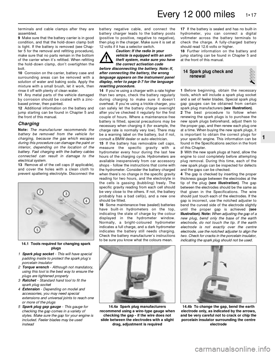
spark plug manufacturers (see illustration).
2The best procedure to follow when
renewing the spark plugs is to purchase the
new spark plugs beforehand, adjust them to
the proper gap, and then renew each plug one
at a time. When buying the new spark plugs, it
is important to obtain the correct plugs for
your specific engine. This information can be
found in the Specifications section in the front
of this Chapter.
3With the new spark plugs at hand, allow the
engine to cool completely before attempting
plug removal. During this time, each of the
new spark plugs can be inspected for defects
and the gaps can be checked.
4The gap is checked by inserting the proper
thickness gauge between the electrodes at the
tip of the plug (see illustration). The gap
between the electrodes should be the same as
that given in the Specifications. The wire
should just touch each of the electrodes. If the
gap is incorrect, use the notched adjuster to
bend the curved side of the electrode slightly
until the proper gap is achieved (see
illustration). Note: When adjusting the gap of a
new plug, bend only the base of the earth
electrode, do not touch the tip. If the earth
electrode is not exactly over the centre
electrode, use the notched adjuster to align the
two. Check for cracks in the porcelain insulator,
indicating the spark plug should not be used.
1•17
14.4b To change the gap, bend the earth
electrode only, as indicated by the arrows,
and be very careful not to crack or chip the
porcelain insulator surrounding the centre
electrode14.4a Spark plug manufacturers
recommend using a wire-type gauge when
checking the gap - if the wire does not
slide between the electrodes with a slight
drag, adjustment is required
14.1 Tools required for changing spark
plugs
1 Spark plug socket- This will have special
padding inside to protect the spark plug’s
porcelain insulator
2 Torque wrench - Although not mandatory,
using this tool is the best way to ensure the
plugs are tightened properly
3 Ratchet - Standard hand tool to fit the
spark plug socket
4 Extension - Depending on model and
accessories, you may need special
extensions and universal joints to reach one
or more of the plugs
5 Spark plug gap gauge- This gauge for
checking the gap comes in a variety of
styles. Make sure the gap for your engine is
included. Feeler blades may be used
instead
1
Every 12 000 miles
Page 35 of 228
Flushing
7Once the system is completely drained,
flush the radiator with fresh water from a
garden hose until the water runs clear at the
drain or bottom hose. If the radiator is
severely corroded, damaged or leaking, it
should be removed (see Chapter 3) and taken
to a radiator repair specialist.
8Flushing in this way will remove sediments
from the radiator, but will not remove rust and
scale from the engine and cooling tube
surfaces. These deposits can be removed by
using a chemical cleaner. Follow the
procedure outlined in the cleaner
manufacturer’s instructions. Remove the
cylinder block drain plug before flushing the
engine.
9On models so equipped, remove the
overflow hose from the coolant recovery
reservoir. Drain the reservoir and flush it with
clean water, then reconnect the hose.
Refilling
10Tighten the radiator drain plug, or
reconnect the radiator bottom hose. Refit and
tighten the cylinder block drain plug.
Four-cylinder engines
11Slowly add new coolant (a 40%/60%
mixture of antifreeze to water) to the radiator
until it is full. Add coolant to the reservoir up
to the lower mark.
12Leave the radiator cap off, and run the
engine in a well-ventilated area until the
thermostat opens (coolant will begin flowing
through the radiator, and the upper radiator
hose will become hot).
13Turn the engine off, and let it cool. Add
more coolant mixture to bring the coolant
level back up to the lip on the radiator filler
neck. On the M40 engine, unscrew the bleed
screw from the top of the radiator, and add
coolant until it comes out of the bleed screw
hole. Refit and tighten the bleed screw.
14Squeeze the upper radiator hose to expel
air, then add more coolant mixture if
necessary. Refit the radiator cap.
15Start the engine, allow it to reach normal
operating temperature, and check for leaks.
Six-cylinder engines
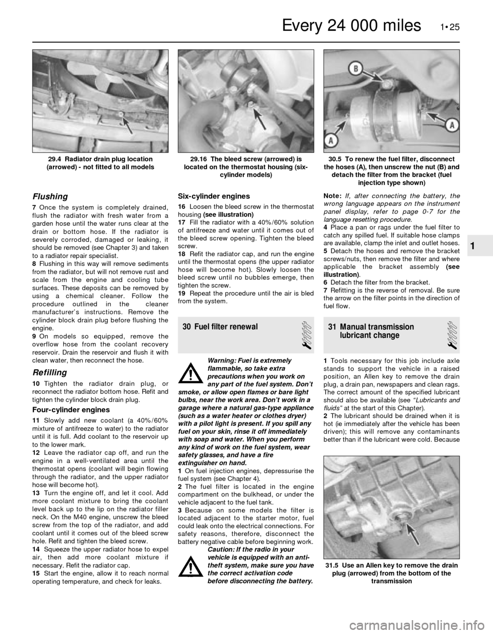
16Loosen the bleed screw in the thermostat
housing (see illustration)
17Fill the radiator with a 40%/60% solution
of antifreeze and water until it comes out of
the bleed screw opening. Tighten the bleed
screw.
18Refit the radiator cap, and run the engine
until the thermostat opens (the upper radiator
hose will become hot). Slowly loosen the
bleed screw until no bubbles emerge, then
tighten the screw.
19Repeat the procedure until the air is bled
from the system.
30 Fuel filter renewal
1
Warning: Fuel is extremely
flammable, so take extra
precautions when you work on
any part of the fuel system. Don’t
smoke, or allow open flames or bare light
bulbs, near the work area. Don’t work in a
garage where a natural gas-type appliance
(such as a water heater or clothes dryer)
with a pilot light is present. If you spill any
fuel on your skin, rinse it off immediately
with soap and water. When you perform
any kind of work on the fuel system, wear
safety glasses, and have a fire
extinguisher on hand.
1On fuel injection engines, depressurise the
fuel system (see Chapter 4).
2The fuel filter is located in the engine
compartment on the bulkhead, or under the
vehicle adjacent to the fuel tank.
3Because on some models the filter is
located adjacent to the starter motor, fuel
could leak onto the electrical connections. For
safety reasons, therefore, disconnect the
battery negative cable before beginning work.
Caution: If the radio in your
vehicle is equipped with an anti-
theft system, make sure you have
the correct activation code
before disconnecting the battery.Note: If, after connecting the battery, the
wrong language appears on the instrument
panel display, refer to page 0-7 for the
language resetting procedure.
4Place a pan or rags under the fuel filter to
catch any spilled fuel. If suitable hose clamps
are available, clamp the inlet and outlet hoses.
5 Detach the hoses and remove the bracket
screws/nuts, then remove the filter and where
applicable the bracket assembly (see
illustration).
6Detach the filter from the bracket.
7Refitting is the reverse of removal. Be sure
the arrow on the filter points in the direction of
fuel flow.
31 Manual transmission
lubricant change
1
1Tools necessary for this job include axle
stands to support the vehicle in a raised
position, an Allen key to remove the drain
plug, a drain pan, newspapers and clean rags.
The correct amount of the specified lubricant
should also be available (see “Lubricants and
fluids”at the start of this Chapter).
2The lubricant should be drained when it is
hot (ie immediately after the vehicle has been
driven); this will remove any contaminants
better than if the lubricant were cold. Because
1•25
30.5 To renew the fuel filter, disconnect
the hoses (A), then unscrew the nut (B) and
detach the filter from the bracket (fuel
injection type shown)29.16 The bleed screw (arrowed) is
located on the thermostat housing (six-
cylinder models)29.4 Radiator drain plug location
(arrowed) - not fitted to all models
31.5 Use an Allen key to remove the drain
plug (arrowed) from the bottom of the
transmission
1
Every 24 000 miles
Page 123 of 228
6
Chapter 6
Engine management and emission control systems
Catalytic converter . . . . . . . . . . . . . . . . . . . . . . . . . . . . . . . . . . . . . . 7
Electronic Control Unit (ECU) - removal and refitting . . . . . . . . . . . . 3
Evaporative emissions control (EVAP) system . . . . . . . . . . . . . . . . . 6
Evaporative emissions control system inspection . . . See Chapter 1
General information . . . . . . . . . . . . . . . . . . . . . . . . . . . . . . . . . . . . . . 1Information sensors . . . . . . . . . . . . . . . . . . . . . . . . . . . . . . . . . . . . . . 4
Motronic engine management system self-diagnosis -
general information . . . . . . . . . . . . . . . . . . . . . . . . . . . . . . . . . . . . 2
Positive crankcase ventilation (PCV) system . . . . . . . . . . . . . . . . . . 5
6•1
Easy,suitable for
novice with little
experienceFairly easy,suitable
for beginner with
some experienceFairly difficult,
suitable for competent
DIY mechanic
Difficult,suitable for
experienced DIY
mechanicVery difficult,
suitable for expert
DIY or professional
Degrees of difficulty Contents
1 General information
To prevent pollution of the atmosphere
from incomplete combustion or evaporation
of the fuel, and to maintain good driveability
and fuel economy, a number of emission
control systems are used on these vehicles.
Not all of these systems are fitted to all
models, but they include the following:
Catalytic converter
Evaporative emission control (EVAP) system
Positive crankcase ventilation (PCV) system
Electronic engine management
The Sections in this Chapter include
general descriptions and checking
procedures within the scope of the home
mechanic, as well as component renewal
procedures (when possible) for each of the
systems listed above.
Before assuming that an emissions control
system is malfunctioning, check the fuel and
ignition systems carefully. The diagnosis of
some emission control devices requires
specialised tools, equipment and training. If
checking and servicing become too difficult,
or if a procedure is beyond your ability,
consult a dealer service department or other
specialist.This doesn’t mean, however, that emission
control systems are particularly difficult to
maintain and repair. You can quickly and
easily perform many checks, and do most of
the regular maintenance at home with
common tune-up and hand tools.
Pay close attention to any special
precautions outlined in this Chapter. It should
be noted that the illustrations of the various
systems may not exactly match the system
fitted on your vehicle because of
changes made by the manufacturer during
production.
2 Motronic engine management
system self-diagnosis-
general information
The Motronic engine management system
control unit (computer) has a built-in self-
diagnosis system, which detects malfunctions
in the system sensors and stores them as
fault codes in its memory. It is not possible
without dedicated test equipment to extract
these fault codes from the control unit.
However, the procedures given in Chapters 4
and 5 may be used to check individual
components and sensors of the Motronic
system. If this fails to pinpoint a fault, then the
vehicle should be taken to a BMW dealer, who
will have the necessary diagnostic
equipment to call up the fault codes from the
control unit. You will then have the
option to repair the fault yourself, or
alternatively have the fault repaired by the
BMW dealer.
3 Electronic control unit (ECU)
- removal and refitting
2
Removal
1The Electronic Control Unit (ECU) is located
either inside the passenger compartment
under the right-hand side of the facia panel on
3-Series models, or in the engine
compartment on the right-hand side on 5-
Series models (see Chapter 4).
2Disconnect the battery negative cable.
Caution: If the radio in your
vehicle is equipped with an anti-
theft system, make sure you
have the correct activation code
before disconnecting the battery. Refer to
the information on page 0-7 at the front of
this manual before detaching the cable.
Note: If, after connecting the battery, the
wrong language appears on the instrument
panel display, refer to page 0-7 for the
language resetting procedure.
3First remove the access cover on models
with the ECU on the right-hand side of the
engine compartment (see Chapter 4).
4If the ECU is located inside the vehicle,
remove the access cover on the right-hand side.
5Unplug the electrical connectors from the
ECU.
6Remove the retaining bolts from the ECU
bracket.
7Carefully remove the ECU. Note: Avoid static
electricity damage to the ECU by wearing rubber
gloves, and do not touch the connector pins.
Refitting
8Refitting is a reversal of removal.
The most frequent cause of
emission system problems is
simply a leaking vacuum hose
or loose wire, so always
check the hose and wiring connections
first.
Page 166 of 228
5Refitting is the reverse of removal. Align the
lid-to-hinge bolts with the marks made during
removal.
6After refitting, close the lid and make sure
it’s in proper alignment with the surrounding
panels. Fore-and-aft and side-to-side
adjustments are controlled by the position of
the hinge bolts in the slots. To make an
adjustment, loosen the hinge bolts, reposition
the lid, and retighten the bolts.
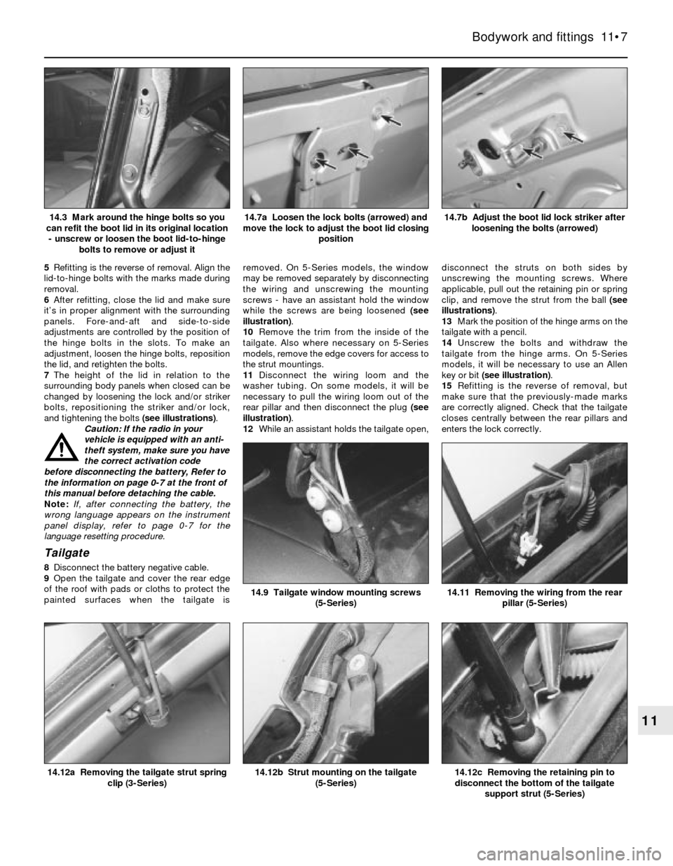
7The height of the lid in relation to the
surrounding body panels when closed can be
changed by loosening the lock and/or striker
bolts, repositioning the striker and/or lock,
and tightening the bolts (see illustrations).
Caution: If the radio in your
vehicle is equipped with an anti-
theft system, make sure you have
the correct activation code
before disconnecting the battery, Refer to
the information on page 0-7 at the front of
this manual before detaching the cable.
Note: If, after connecting the battery, the
wrong language appears on the instrument
panel display, refer to page 0-7 for the
language resetting procedure.
Tailgate
8Disconnect the battery negative cable.
9Open the tailgate and cover the rear edge
of the roof with pads or cloths to protect the
painted surfaces when the tailgate isremoved. On 5-Series models, the window
may be removed separately by disconnecting
the wiring and unscrewing the mounting
screws - have an assistant hold the window
while the screws are being loosened (see
illustration).
10Remove the trim from the inside of the
tailgate. Also where necessary on 5-Series
models, remove the edge covers for access to
the strut mountings.
11Disconnect the wiring loom and the
washer tubing. On some models, it will be
necessary to pull the wiring loom out of the
rear pillar and then disconnect the plug (see
illustration).
12While an assistant holds the tailgate open,disconnect the struts on both sides by
unscrewing the mounting screws. Where
applicable, pull out the retaining pin or spring
clip, and remove the strut from the ball (see
illustrations).
13Mark the position of the hinge arms on the
tailgate with a pencil.
14Unscrew the bolts and withdraw the
tailgate from the hinge arms. On 5-Series
models, it will be necessary to use an Allen
key or bit (see illustration).
15Refitting is the reverse of removal, but
make sure that the previously-made marks
are correctly aligned. Check that the tailgate
closes centrally between the rear pillars and
enters the lock correctly.
Bodywork and fittings 11•7
14.7b Adjust the boot lid lock striker after
loosening the bolts (arrowed)14.7a Loosen the lock bolts (arrowed) and
move the lock to adjust the boot lid closing
position14.3 Mark around the hinge bolts so you
can refit the boot lid in its original location
- unscrew or loosen the boot lid-to-hinge
bolts to remove or adjust it
14.12c Removing the retaining pin to
disconnect the bottom of the tailgate
support strut (5-Series)14.12b Strut mounting on the tailgate
(5-Series)14.12a Removing the tailgate strut spring
clip (3-Series)
14.11 Removing the wiring from the rear
pillar (5-Series)14.9 Tailgate window mounting screws
(5-Series)
11
Page 170 of 228
Finding a short-circuit
One method of finding a short-circuit is to
remove the fuse and connect a test light or
voltmeter in its place. There should be no
voltage present in the circuit. Move the
electrical connectors from side-to-side while
watching the test light. If the bulb goes on,
there is a short to earth somewhere in that
area, probably where the insulation has been
rubbed through. The same test can be
performed on each component in a circuit,
even a switch.
Earth check
Perform a earth check to see whether a
component is properly earthed (passing
current back via the vehicle body). Disconnect
the battery, and connect one lead of a self-
powered test light (often known as a
continuity tester) to a known good earth.
Connect the other lead to the wire or earth
connection being tested. The bulb should
light, indicating a good earth connection. If
not, dismantle the connection, and clean all
relevant parts thoroughly. When re-making
the connection, use serrated (shakeproof)
washers if possible, and tighten all bolts, etc,
securely.
Caution: If the radio in your
vehicle is equipped with an anti-
theft system, make sure you have
the correct activation code
before disconnecting the battery, Refer to
the information on page 0-7 at the front of
this manual before detaching the cable.
Note: If, after connecting the battery, the
wrong language appears on the instrument
panel display, refer to page 0-7 for the
language resetting procedure.
Continuity check
A continuity check determines if there are
any breaks in a circuit - if it is conducting
electricity properly. With the circuit off (no
power in the circuit), a self-powered continuity
tester can be used to check the circuit.
Connect the test leads to both ends of the
circuit, and if the test light comes on, the
circuit is passing current properly. If the light
doesn’t come on, there is a break somewhere
in the circuit. The same procedure can be
used to test a switch, by connecting the
continuity tester to the power-in and power-
out sides of the switch. With the switch turned
on, the test light should come on.
Finding an open-circuit
When diagnosing for possible open-
circuits, it is often difficult to locate them by
sight, because oxidation or terminal
misalignment are hidden by the connectors.
Intermittent problems are often caused by
oxidised or loose connections. Merely
wiggling an electrical connector may correct
the open-circuit condition, albeit temporarily.
Dismantle the connector, and spray with a
water-dispersant aerosol. On simpler
connectors, it may be possible to carefullybend the connector pins inside, to improve
the metal-to-metal contact - don’t damage
the connector in the process, however.
3 Fuses- general information
1
The electrical circuits of the vehicle are
protected by a combination of fuses and
circuit breakers. The fusebox is located in the
left corner of the engine compartment (see
illustration). On some later models, it is
located under the rear seat cushion.
Each of the fuses is designed to protect a
specific circuit, and on some models, the
various circuits are identified on the fuse
panel itself.
Miniaturised fuses are employed in the
fuseboxes. These compact fuses, with blade
terminal design, allow fingertip removal and
renewal. If an electrical component fails,
always check the fuse first. A blown fuse is
easily identified through the clear plastic
body. Visually inspect the element for
evidence of damage. If a continuity check is
called for, the blade terminal tips are exposed
in the fuse body.
Be sure to renew blown fuses with the
correct type. Fuses of different ratings are
physically interchangeable, but only fuses of
the proper rating should be used. Replacing a
fuse with one of a higher or lower value than
specified is not recommended. Each electrical
circuit needs a specific amount of protection.
The amperage value of each fuse is moulded
into the fuse body.
If the new fuse immediately fails, don’t
renew it again until the cause of the problem
is isolated and corrected. In most cases, the
cause will be a short-circuit in the wiring
caused by a broken or deteriorated wire.
4 Relays- general information
1
Several electrical accessories in the vehicle
use relays to transmit the electrical signal to
the component. If the relay is defective, thatcomponent will not operate properly. Relays
are electrically-operated switches, which are
often used in circuits drawing high levels of
current, or where more complex switching
arrangements are required.
The various relays are grouped together for
convenience in several locations under the
dash and in the engine compartment (see
accompanying illustration and illus-
tration 3.1).
If a faulty relay is suspected, it can be
removed and tested by a dealer or qualified
automotive electrician. No overhaul is
possible. Like fuses, defective relays must be
replaced with the correct type; some relays
look identical, but perform very different
functions.
5 Direction indicator/hazard
warning flasher unit- check
and renewal
2
Warning: Some later models are
equipped with an airbag or
Supplemental Restraint System
(SRS). To avoid possible damage
to this system, the manufacturer
recommends that, on airbag-equipped
models, the following procedure should be
left to a dealer service department, or
other specialist, because of the special
tools and techniques required. There is a
risk of injury if the airbag is accidentally
triggered.
1The direction indicator/hazard flasher unit is
a small canister- or box-shaped unit located
in the wiring harness on or near the steering
column. Access is gained by removing the
steering column shrouds (see illustration).
2When the flasher unit is functioning
properly, a regular clicking noise can be heard
from it when the indicators or hazard flashers
are switched on. If the direction indicators fail
on one side or the other, and the flasher unit
does not make its characteristic clicking
sound, a faulty direction indicator bulb is
indicated.
3If both direction indicators fail to blink, the
problem may be due to a blown fuse, a faulty
flasher unit, a broken switch or a loose or open
connection. If a quick check of the fusebox
12•2 Body electrical systems
4.2 Engine compartment relays3.1 The fusebox is located in the engine
compartment under a cover - the box also
includes several relays