height BMW 3 SERIES 1983 E30 Workshop Manual
[x] Cancel search | Manufacturer: BMW, Model Year: 1983, Model line: 3 SERIES, Model: BMW 3 SERIES 1983 E30Pages: 228, PDF Size: 7.04 MB
Page 67 of 228
that they’re suitable for use in a rebuilt engine
(take the springs to a machine shop for this
check).
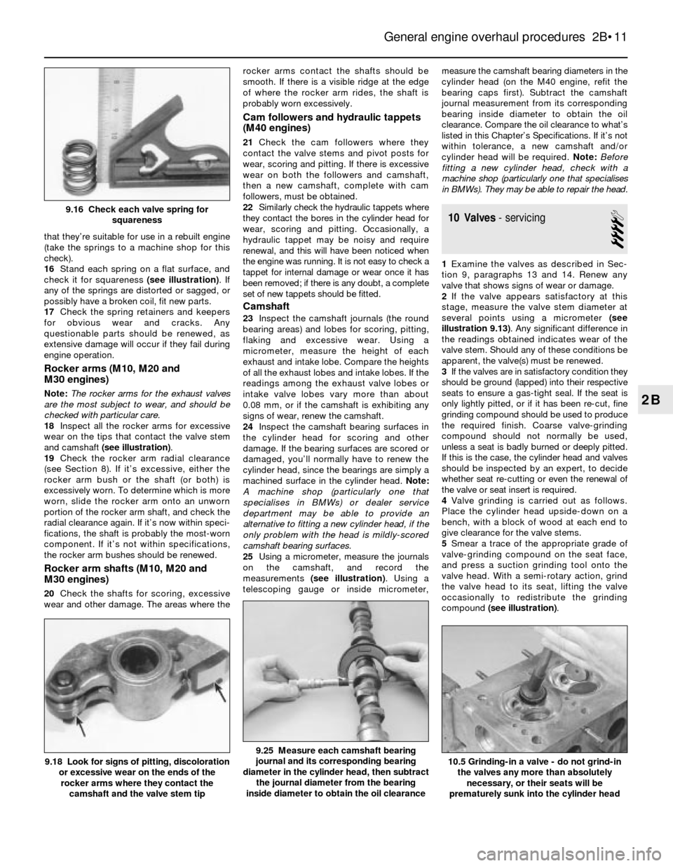
16Stand each spring on a flat surface, and
check it for squareness (see illustration). If
any of the springs are distorted or sagged, or
possibly have a broken coil, fit new parts.
17Check the spring retainers and keepers
for obvious wear and cracks. Any
questionable parts should be renewed, as
extensive damage will occur if they fail during
engine operation.
Rocker arms (M10, M20 and
M30 engines)
Note:The rocker arms for the exhaust valves
are the most subject to wear, and should be
checked with particular care.
18Inspect all the rocker arms for excessive
wear on the tips that contact the valve stem
and camshaft (see illustration).
19Check the rocker arm radial clearance
(see Section 8). If it’s excessive, either the
rocker arm bush or the shaft (or both) is
excessively worn. To determine which is more
worn, slide the rocker arm onto an unworn
portion of the rocker arm shaft, and check the
radial clearance again. If it’s now within speci-
fications, the shaft is probably the most-worn
component. If it’s not within specifications,
the rocker arm bushes should be renewed.
Rocker arm shafts (M10, M20 and
M30 engines)
20Check the shafts for scoring, excessive
wear and other damage. The areas where therocker arms contact the shafts should be
smooth. If there is a visible ridge at the edge
of where the rocker arm rides, the shaft is
probably worn excessively.
Cam followers and hydraulic tappets
(M40 engines)
21Check the cam followers where they
contact the valve stems and pivot posts for
wear, scoring and pitting. If there is excessive
wear on both the followers and camshaft,
then a new camshaft, complete with cam
followers, must be obtained.
22Similarly check the hydraulic tappets where
they contact the bores in the cylinder head for
wear, scoring and pitting. Occasionally, a
hydraulic tappet may be noisy and require
renewal, and this will have been noticed when
the engine was running. It is not easy to check a
tappet for internal damage or wear once it has
been removed; if there is any doubt, a complete
set of new tappets should be fitted.
Camshaft
23Inspect the camshaft journals (the round
bearing areas) and lobes for scoring, pitting,
flaking and excessive wear. Using a
micrometer, measure the height of each
exhaust and intake lobe. Compare the heights
of all the exhaust lobes and intake lobes. If the
readings among the exhaust valve lobes or
intake valve lobes vary more than about
0.08 mm, or if the camshaft is exhibiting any
signs of wear, renew the camshaft.
24Inspect the camshaft bearing surfaces in
the cylinder head for scoring and other
damage. If the bearing surfaces are scored or
damaged, you’ll normally have to renew the
cylinder head, since the bearings are simply a
machined surface in the cylinder head. Note:
A machine shop (particularly one that
specialises in BMWs) or dealer service
department may be able to provide an
alternative to fitting a new cylinder head, if the
only problem with the head is mildly-scored
camshaft bearing surfaces.
25Using a micrometer, measure the journals
on the camshaft, and record the
measurements (see illustration). Using a
telescoping gauge or inside micrometer,measure the camshaft bearing diameters in the
cylinder head (on the M40 engine, refit the
bearing caps first). Subtract the camshaft
journal measurement from its corresponding
bearing inside diameter to obtain the oil
clearance. Compare the oil clearance to what’s
listed in this Chapter’s Specifications. If it’s not
within tolerance, a new camshaft and/or
cylinder head will be required. Note:Before
fitting a new cylinder head, check with a
machine shop (particularly one that specialises
in BMWs). They may be able to repair the head.
10 Valves- servicing
4
1Examine the valves as described in Sec-
tion 9, paragraphs 13 and 14. Renew any
valve that shows signs of wear or damage.
2If the valve appears satisfactory at this
stage, measure the valve stem diameter at
several points using a micrometer (see
illustration 9.13). Any significant difference in
the readings obtained indicates wear of the
valve stem. Should any of these conditions be
apparent, the valve(s) must be renewed.
3If the valves are in satisfactory condition they
should be ground (lapped) into their respective
seats to ensure a gas-tight seal. If the seat is
only lightly pitted, or if it has been re-cut, fine
grinding compound should be used to produce
the required finish. Coarse valve-grinding
compound should not normally be used,
unless a seat is badly burned or deeply pitted.
If this is the case, the cylinder head and valves
should be inspected by an expert, to decide
whether seat re-cutting or even the renewal of
the valve or seat insert is required.
4Valve grinding is carried out as follows.
Place the cylinder head upside-down on a
bench, with a block of wood at each end to
give clearance for the valve stems.
5Smear a trace of the appropriate grade of
valve-grinding compound on the seat face,
and press a suction grinding tool onto the
valve head. With a semi-rotary action, grind
the valve head to its seat, lifting the valve
occasionally to redistribute the grinding
compound (see illustration).
General engine overhaul procedures 2B•11
9.25 Measure each camshaft bearing
journal and its corresponding bearing
diameter in the cylinder head, then subtract
the journal diameter from the bearing
inside diameter to obtain the oil clearance9.18 Look for signs of pitting, discoloration
or excessive wear on the ends of the
rocker arms where they contact the
camshaft and the valve stem tip10.5 Grinding-in a valve - do not grind-in
the valves any more than absolutely
necessary, or their seats will be
prematurely sunk into the cylinder head
2B
9.16 Check each valve spring for
squareness
Page 72 of 228
7Wipe the oil out of the cylinder, and repeat
the procedure for the remaining cylinders.
8After the honing job is complete, chamfer
the top edges of the cylinder bores with a
small file, so the rings won’t catch when the
pistons are refitted. Be very careful not to nick
the cylinder walls with the end of the file.
9The entire engine block must be washed
again very thoroughly with warm, soapy
water, to remove all traces of the abrasive grit
produced during the honing operation. Note:
The bores can be considered clean when a
lint-free white cloth - dampened with clean
engine oil - used to wipe them out doesn’t
pick up any more honing residue, which will
show up as grey areas on the cloth.Be sure to
run a brush through all oil holes and galleries,
and flush them with running water.
10After rinsing, dry the block, and apply a
coat of light rust-preventive oil to all machined
surfaces. Wrap the block in a plastic bag to
keep it clean, and set it aside until
reassembly.
18 Pistons/connecting rods-
inspection
3
1Before the inspection process can be
carried out, the piston/connecting rod
assemblies must be cleaned and the original
piston rings removed from the pistons.Note:
Always use new piston rings when the engine
is reassembled.
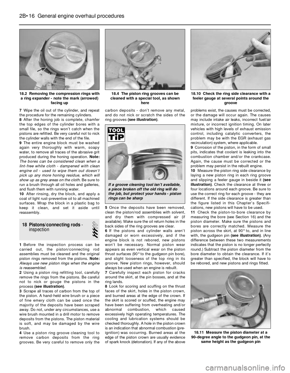
2Using a piston ring refitting tool, carefully
remove the rings from the pistons. Be careful
not to nick or gouge the pistons in the
process (see illustration).
3Scrape all traces of carbon from the top of
the piston. A hand-held wire brush or a piece
of fine emery cloth can be used once the
majority of the deposits have been scraped
away. Do not, under any circumstances, use a
wire brush mounted in a drill motor to remove
deposits from the pistons. The piston material
is soft, and may be damaged by the wire
brush.
4Use a piston ring groove cleaning tool to
remove carbon deposits from the ring
grooves. Be very careful to remove only thecarbon deposits - don’t remove any metal,
and do not nick or scratch the sides of the
ring grooves (see illustration).
5Once the deposits have been removed,
clean the piston/rod assemblies with solvent,
and dry them with compressed air (if
available). Make sure the oil return holes in the
back sides of the ring grooves are clear.
6If the pistons and cylinder walls aren’t
damaged or worn excessively, and if the
engine block is not rebored, new pistons
won’t be necessary. Normal piston wear
appears as even vertical wear on the piston
thrust surfaces (90° to the gudgeon pin bore),
and slight looseness of the top ring in its
groove. New piston rings, however, should
always be used when an engine is rebuilt.
7Carefully inspect each piston for cracks
around the skirt, at the pin bosses, and at the
ring lands.
8Look for scoring and scuffing on the thrust
faces of the skirt, holes in the piston crown,
and burned areas at the edge of the crown. If
the skirt is scored or scuffed, the engine may
have been suffering from overheating and/or
abnormal combustion, which caused
excessively high operating temperatures. The
cooling and lubrication systems should be
checked thoroughly. A hole in the piston crown
is an indication that abnormal combustion (pre-
ignition) was occurring. Burned areas at the
edge of the piston crown are usually evidence
of spark knock (detonation). If any of the aboveproblems exist, the causes must be corrected,
or the damage will occur again. The causes
may include intake air leaks, incorrect fuel/air
mixture, or incorrect ignition timing. On later
vehicles with high levels of exhaust emission
control, including catalytic converters, the
problem may be with the EGR (exhaust gas
recirculation) system, where applicable.
9Corrosion of the piston, in the form of small
pits, indicates that coolant is leaking into the
combustion chamber and/or the crankcase.
Again, the cause must be corrected or the
problem may persist in the rebuilt engine.
10Measure the piston ring side clearance by
laying a new piston ring in each ring groove
and slipping a feeler gauge in beside it(see
illustration). Check the clearance at three or
four locations around each groove. Be sure to
use the correct ring for each groove - they are
different. If the side clearance is greater than
the figure listed in this Chapter’s Specifi-
cations, new pistons will have to be used.
11Check the piston-to-bore clearance by
measuring the bore (see Section 16) and the
piston diameter. Make sure the pistons and
bores are correctly matched. Measure the
piston across the skirt, at 90° to, and in line
with, the gudgeon pin (see illustration). (Any
difference between these two measurements
indicates that the piston is no longer perfectly
round.) Subtract the piston diameter from the
bore diameter to obtain the clearance. If it’s
greater than specified, the block will have to
be rebored, and new pistons and rings fitted.
2B•16 General engine overhaul procedures
18.11 Measure the piston diameter at a
90-degree angle to the gudgeon pin, at the
same height as the gudgeon pin
18.10 Check the ring side clearance with a
feeler gauge at several points around the
groove18.4 The piston ring grooves can be
cleaned with a special tool, as shown
here18.2 Removing the compression rings with
a ring expander - note the mark (arrowed)
facing up
If a groove cleaning tool isn’t available,
a piece broken off the old ring will do
the job, but protect your hands - piston
rings can be sharp
Page 129 of 228

9
General
Brake fluid type . . . . . . . . . . . . . . . . . . . . . . . . . . . . . . . . . . . . . . . . . . . . See Chapter 1
Disc brakes
Minimum brake pad thickness . . . . . . . . . . . . . . . . . . . . . . . . . . . . . . . . See Chapter 1
Brake disc minimum permissible thickness (wear limit)*
Front
3-Series
Solid discs . . . . . . . . . . . . . . . . . . . . . . . . . . . . . . . . . . . . . . . . . . 10.7 mm
Ventilated discs . . . . . . . . . . . . . . . . . . . . . . . . . . . . . . . . . . . . . . 20.0 mm
5-Series
Solid discs . . . . . . . . . . . . . . . . . . . . . . . . . . . . . . . . . . . . . . . . . . 10.0 mm
Ventilated discs . . . . . . . . . . . . . . . . . . . . . . . . . . . . . . . . . . . . . . 20.0 mm
Rear . . . . . . . . . . . . . . . . . . . . . . . . . . . . . . . . . . . . . . . . . . . . . . . . . . 8.0 mm
Brake disc minimum thickness after machining
Front
3-Series
Solid discs . . . . . . . . . . . . . . . . . . . . . . . . . . . . . . . . . . . . . . . . . . 11.1 mm
Ventilated discs . . . . . . . . . . . . . . . . . . . . . . . . . . . . . . . . . . . . . . 20.4 mm
5-Series
Solid discs . . . . . . . . . . . . . . . . . . . . . . . . . . . . . . . . . . . . . . . . . . 10.4 mm
Ventilated discs . . . . . . . . . . . . . . . . . . . . . . . . . . . . . . . . . . . . . . 20.4 mm
Rear . . . . . . . . . . . . . . . . . . . . . . . . . . . . . . . . . . . . . . . . . . . . . . . . . . 8.4 mm
Parallelism (difference between any two measurements) . . . . . . . . . . . 0.02 mm
Maximum disc run-out . . . . . . . . . . . . . . . . . . . . . . . . . . . . . . . . . . . . . . 0.2 mm
*Refer to marks cast into the disc (they supersede information printed here)
Brake pedal adjustments
Brake pedal/servo pushrod adjustment (A) (3-Series) . . . . . . . . . . . . . . 125 mm
Brake pedal height (pedal-to-bulkhead distance)
3-Series
Left-hand-drive . . . . . . . . . . . . . . . . . . . . . . . . . . . . . . . . . . . . . . . . 235 mm
Right-hand-drive . . . . . . . . . . . . . . . . . . . . . . . . . . . . . . . . . . . . . . . 273 mm
5-Series . . . . . . . . . . . . . . . . . . . . . . . . . . . . . . . . . . . . . . . . . . . . . . . . 245 mm
Stop-light switch adjustment (dimension A - see text) . . . . . . . . . . . . . . 5.0 mm to 6.0 mm
Handbrake
Handbrake shoe lining minimum thickness . . . . . . . . . . . . . . . . . . . . . . 1.5 mm
Handbrake lever travel . . . . . . . . . . . . . . . . . . . . . . . . . . . . . . . . . . . . . . 5 to 8 clicks
Chapter 9 Braking system
Anti-lock brake system (ABS) - general information . . . . . . . . . . . . . 2
Brake check . . . . . . . . . . . . . . . . . . . . . . . . . . . . . . . . See Chapter 1
Brake disc - inspection, removal and refitting . . . . . . . . . . . . . . . . . 5
Brake fluid level check . . . . . . . . . . . . . . . . . . . . . . . . See Chapter 1
Brake hoses and lines - inspection and renewal . . . . . . . . . . . . . . . . 15
Brake hydraulic system - bleeding . . . . . . . . . . . . . . . . . . . . . . . . . . 16
Brake pedal - adjustment . . . . . . . . . . . . . . . . . . . . . . . . . . . . . . . . . 13
Brake vacuum servo - check, removal and refitting . . . . . . . . . . . . . 8
Disc brake caliper - removal, overhaul and refitting . . . . . . . . . . . . . 4Disc brake pads - renewal . . . . . . . . . . . . . . . . . . . . . . . . . . . . . . . . 3
Drum brake shoes - renewal . . . . . . . . . . . . . . . . . . . . . . . . . . . . . . . 6
General information . . . . . . . . . . . . . . . . . . . . . . . . . . . . . . . . . . . . . . 1
Handbrake assembly - check, removal and refitting . . . . . . . . . . . . 12
Handbrake - adjustment . . . . . . . . . . . . . . . . . . . . . . . . . . . . . . . . . . 11
Handbrake cable(s) - renewal . . . . . . . . . . . . . . . . . . . . . . . . . . . . . . 10
Hydraulic brake servo - description, removal and refitting . . . . . . . . 9
Master cylinder - removal and refitting . . . . . . . . . . . . . . . . . . . . . . . 7
Stop-light switch - check and adjustment . . . . . . . . . . . . . . . . . . . . 14
9•1
Easy,suitable for
novice with little
experienceFairly easy,suitable
for beginner with
some experienceFairly difficult,
suitable for competent
DIY mechanic
Difficult,suitable for
experienced DIY
mechanicVery difficult,
suitable for expert
DIY or professional
Degrees of difficulty
Specifications Contents
Page 132 of 228
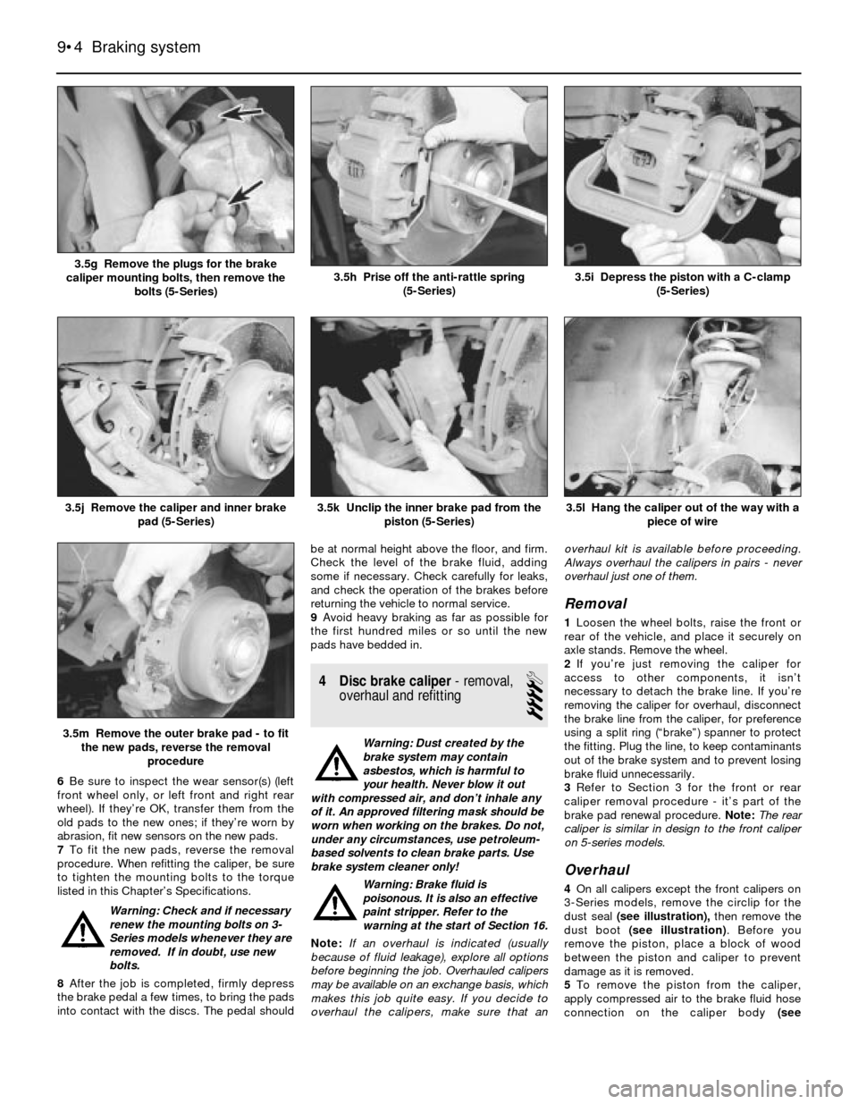
6Be sure to inspect the wear sensor(s) (left
front wheel only, or left front and right rear
wheel). If they’re OK, transfer them from the
old pads to the new ones; if they’re worn by
abrasion, fit new sensors on the new pads.
7To fit the new pads, reverse the removal
procedure. When refitting the caliper, be sure
to tighten the mounting bolts to the torque
listed in this Chapter’s Specifications.
Warning: Check and if necessary
renew the mounting bolts on 3-
Series models whenever they are
removed. If in doubt, use new
bolts.
8After the job is completed, firmly depress
the brake pedal a few times, to bring the pads
into contact with the discs. The pedal shouldbe at normal height above the floor, and firm.
Check the level of the brake fluid, adding
some if necessary. Check carefully for leaks,
and check the operation of the brakes before
returning the vehicle to normal service.
9Avoid heavy braking as far as possible for
the first hundred miles or so until the new
pads have bedded in.
4 Disc brake caliper- removal,
overhaul and refitting
4
Warning: Dust created by the
brake system may contain
asbestos, which is harmful to
your health. Never blow it out
with compressed air, and don’t inhale any
of it. An approved filtering mask should be
worn when working on the brakes. Do not,
under any circumstances, use petroleum-
based solvents to clean brake parts. Use
brake system cleaner only!
Warning: Brake fluid is
poisonous. It is also an effective
paint stripper. Refer to the
warning at the start of Section 16.
Note:If an overhaul is indicated (usually
because of fluid leakage), explore all options
before beginning the job. Overhauled calipers
may be available on an exchange basis, which
makes this job quite easy. If you decide to
overhaul the calipers, make sure that anoverhaul kit is available before proceeding.
Always overhaul the calipers in pairs - never
overhaul just one of them.
Removal
1Loosen the wheel bolts, raise the front or
rear of the vehicle, and place it securely on
axle stands. Remove the wheel.
2If you’re just removing the caliper for
access to other components, it isn’t
necessary to detach the brake line. If you’re
removing the caliper for overhaul, disconnect
the brake line from the caliper, for preference
using a split ring (“brake”) spanner to protect
the fitting. Plug the line, to keep contaminants
out of the brake system and to prevent losing
brake fluid unnecessarily.
3Refer to Section 3 for the front or rear
caliper removal procedure - it’s part of the
brake pad renewal procedure. Note:The rear
caliper is similar in design to the front caliper
on 5-series models.
Overhaul
4On all calipers except the front calipers on
3-Series models, remove the circlip for the
dust seal (see illustration),then remove the
dust boot (see illustration). Before you
remove the piston, place a block of wood
between the piston and caliper to prevent
damage as it is removed.
5To remove the piston from the caliper,
apply compressed air to the brake fluid hose
connection on the caliper body (see
9•4 Braking system
3.5l Hang the caliper out of the way with a
piece of wire
3.5m Remove the outer brake pad - to fit
the new pads, reverse the removal
procedure
3.5k Unclip the inner brake pad from the
piston (5-Series)3.5j Remove the caliper and inner brake
pad (5-Series)
3.5i Depress the piston with a C-clamp
(5-Series)3.5h Prise off the anti-rattle spring
(5-Series)3.5g Remove the plugs for the brake
caliper mounting bolts, then remove the
bolts (5-Series)
Page 138 of 228
expel the air from the master cylinder. A large
Phillips screwdriver can be used to push on
the piston assembly.
11To prevent air from being drawn back into
the master cylinder, the plug must be refitted
and tightened down before releasing the
pressure on the piston assembly.
12Repeat the procedure until brake fluid free
of air bubbles is expelled from the brake line
outlet hole. Repeat the procedure with the
other outlet hole and plug. Be sure to keep the
master cylinder reservoir filled with brake
fluid, to prevent the introduction of air into the
system.
13High pressure is not involved in the bench
bleeding procedure, so the plugs described
above need not be refitted each time the
piston is released, if wished. Instead, before
releasing the piston, simply put your finger
tightly over the hole to keep air from being
drawn back into the master cylinder. Wait
several seconds for brake fluid to be drawn
from the reservoir into the piston bore, then
depress the piston again, removing your
finger as brake fluid is expelled. Be sure to put
your finger back over the hole each time
before releasing the piston, and when the
bleeding procedure is complete for that outlet,
refit the plug and tighten it up before going on
to the other port.
Refitting
14Refit the master cylinder (together with a
new O-ring) over the studs on the brake servo,
and tighten the mounting nuts only finger-tight
at this time.
15Thread the brake line fittings into the
master cylinder. Since the master cylinder is
still a bit loose, it can be moved slightly in
order for the fittings to thread in easily. Do not
strip the threads as the fittings are tightened.
16Tighten the brake fittings securely, and
the mounting nuts to the torque listed in this
Chapter’s Specifications.
17Fill the master cylinder reservoir with fluid,
then bleed the master cylinder (only if the
cylinder has not already been bled) and the
brake system as described in Section 16.
18To bleed the cylinder on the vehicle, have
an assistant pump the brake pedal severaltimes and then hold the pedal to the floor.
Loosen the fitting nut to allow air and fluid to
escape, then tighten the nut. Repeat this
procedure on both fittings until the fluid is
clear of air bubbles. Test the operation of the
brake system carefully before returning the
vehicle to normal service.
8 Brake vacuum servo-
check, removal and refitting
3
Operating check
1Depress the brake pedal several times with
the engine off, until there is no change in the
pedal travel.
2Depress and hold the pedal, then start the
engine. If the pedal goes down slightly,
operation is normal.
Airtightness check
3Start the engine, and turn it off after one or
two minutes. Depress the brake pedal several
times slowly. If the pedal goes down further
the first time but gradually rises after the
second or third depression, the servo is
airtight.
4Depress the brake pedal while the engine is
running, then stop the engine with the pedal
depressed. If there is no change in the pedal
travel after holding the pedal for 30 seconds,
the servo is airtight.
Removal and refitting
5Dismantling the vacuum servo requires
special tools, and cannot be performed by the
home mechanic. If a problem develops, it is
recommended that a new unit be fitted.
6Remove the master cylinder as described in
Section 7.
7Disconnect the vacuum hose from the
brake servo.
8Working in the passenger compartment,
remove the glovebox and lower left-hand trim
panels.
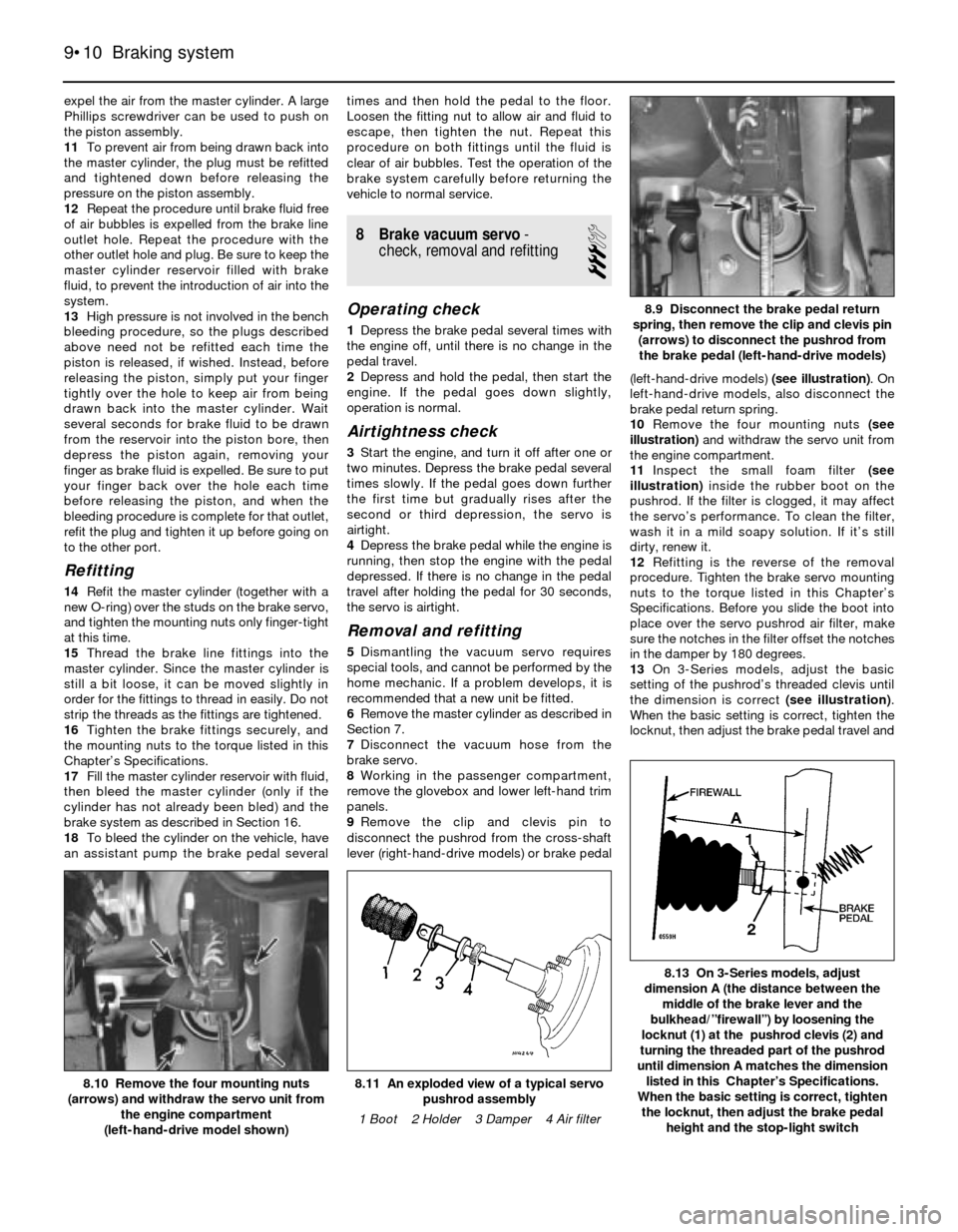
9Remove the clip and clevis pin to
disconnect the pushrod from the cross-shaft
lever (right-hand-drive models) or brake pedal(left-hand-drive models) (see illustration). On
left-hand-drive models, also disconnect the
brake pedal return spring.
10Remove the four mounting nuts (see
illustration)and withdraw the servo unit from
the engine compartment.
11Inspect the small foam filter (see
illustration)inside the rubber boot on the
pushrod. If the filter is clogged, it may affect
the servo’s performance. To clean the filter,
wash it in a mild soapy solution. If it’s still
dirty, renew it.
12Refitting is the reverse of the removal
procedure. Tighten the brake servo mounting
nuts to the torque listed in this Chapter’s
Specifications. Before you slide the boot into
place over the servo pushrod air filter, make
sure the notches in the filter offset the notches
in the damper by 180 degrees.
13On 3-Series models, adjust the basic
setting of the pushrod’s threaded clevis until
the dimension is correct (see illustration).
When the basic setting is correct, tighten the
locknut, then adjust the brake pedal travel and
9•10 Braking system
8.13 On 3-Series models, adjust
dimension A (the distance between the
middle of the brake lever and the
bulkhead/”firewall”) by loosening the
locknut (1) at the pushrod clevis (2) and
turning the threaded part of the pushrod
until dimension A matches the dimension
listed in this Chapter’s Specifications.
When the basic setting is correct, tighten
the locknut, then adjust the brake pedal
height and the stop-light switch
8.11 An exploded view of a typical servo
pushrod assembly
1 Boot 2 Holder 3 Damper 4 Air filter8.10 Remove the four mounting nuts
(arrows) and withdraw the servo unit from
the engine compartment
(left-hand-drive model shown)
8.9 Disconnect the brake pedal return
spring, then remove the clip and clevis pin
(arrows) to disconnect the pushrod from
the brake pedal (left-hand-drive models)
Page 139 of 228
the stop-light switch (see Section 13). Note:
On right-hand-drive models, the brake pedal
in on the right-hand side of the vehicle, and is
connected to the left-hand side by a cross-
shaft. The adjustment is carried out on the
pushrod at the left-hand side, but the
dimension is measured at the pedal on the
right-hand side.
14On 5-Series models, adjust the brake
pedal height and the stop-light switch (see
Section 13).
15Refit the master cylinder (see Section 7)
and attach the vacuum hose.
16Carefully test the operation of the brakes
before returning the vehicle to normal use
9 Hydraulic brake servo-
description, removal and
refitting
3
Warning: Brake fluid is
poisonous. It is also an effective
paint stripper. Refer to the
warning at the start of Section 16.
Description
1On 5-Series E28 (“old-shape”) models, a
hydraulic brake servo system is fitted. The
servo unit, located between the brake pedal
(left-hand-drive) or cross-shaft lever (right-
hand-drive) and the master cylinder, is
operated by hydraulic pressure generated by
the power steering pump. When the engine is
running, the power steering pump supplies
hydraulic pressure to a power flow regulator/
accumulator. The regulator/accumulator
stores and regulates the pressure to the
hydraulic brake servo. When you press the
brake pedal, the pressure in the servo helps
actuate the master cylinder, reducing pedal
effort.
2The hydraulic brake servo cannot be
overhauled; if it fails, a new one must be fitted.
Testing the system requires special tools, so
even fault diagnosis is beyond the scope of
the home mechanic. If the system fails, take it
to a dealer service department or other
qualified garage for repairs.
Removal and refitting
3With the engine off, discharge the hydraulic
accumulator by depressing the brake pedal
20 times or more.
4Remove the master cylinder (see Section 7).
5Clean the area around the return and
supply line fittings, then disconnect them.
Plug the lines, to prevent dirt from entering the
system, and to prevent further fluid loss.
Caution: Even a particle of dirt
can damage the servo, so be
extremely careful to prevent dirt
from entering the system while
the lines are disconnected.
6Working from inside the passenger
compartment, remove the lower left trim
panels above the brake pedal (left-hand-drive
models) or glovebox and trim (right-hand-drive models). On left-hand-drive models, also
disconnect the pedal return spring.
7Prise off the retaining clip, and disconnect
the pushrod from the brake pedal (see
illustration 8.9) or cross-shaft lever.
8Remove the four mounting nuts and
remove the brake servo (see illus-
tration 8.10).
9Refitting is the reverse of removal. Tighten
the hydraulic lines to the torque listed in this
Chapter’s Specifications. Note:Don’t try to
tighten these fittings without a torque wrench.
If they’re loose, they can leak, which can affect
system operation; if they’re tight, they can be
damaged, and they’ll also leak. You’ll need a
crowfoot-type split ring (“brake”) attachment
for your torque wrench to tighten the fittings
properly.
10When you’re done, bleed the brake
hydraulic system (Section 16) and adjust the
brake pedal travel and the stop-light switch
(see Section 13).
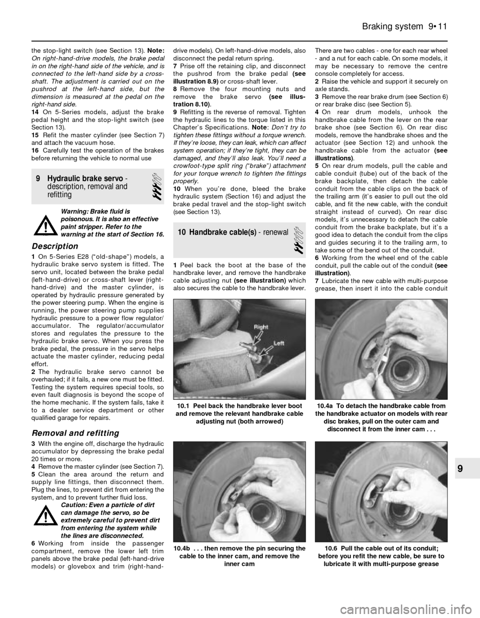
10 Handbrake cable(s)- renewal
2
1Peel back the boot at the base of the
handbrake lever, and remove the handbrake
cable adjusting nut (see illustration)which
also secures the cable to the handbrake lever.There are two cables - one for each rear wheel
- and a nut for each cable. On some models, it
may be necessary to remove the centre
console completely for access.
2Raise the vehicle and support it securely on
axle stands.
3Remove the rear brake drum (see Section 6)
or rear brake disc (see Section 5).
4On rear drum models, unhook the
handbrake cable from the lever on the rear
brake shoe (see Section 6). On rear disc
models, remove the handbrake shoes and the
actuator (see Section 12) and unhook the
handbrake cable from the actuator (see
illustrations).
5On rear drum models, pull the cable and
cable conduit (tube) out of the back of the
brake backplate, then detach the cable
conduit from the cable clips on the back of
the trailing arm (it’s easier to pull out the old
cable, and fit the new cable, with the conduit
straight instead of curved). On rear disc
models, it’s unnecessary to detach the cable
conduit from the brake backplate, but it’s a
good idea to detach the conduit from the clips
and guides securing it to the trailing arm, to
take some of the bend out of the conduit.
6Working from the wheel end of the cable
conduit, pull the cable out of the conduit (see
illustration).
7Lubricate the new cable with multi-purpose
grease, then insert it into the cable conduit
Braking system 9•11
10.1 Peel back the handbrake lever boot
and remove the relevant handbrake cable
adjusting nut (both arrowed)
10.6 Pull the cable out of its conduit;
before you refit the new cable, be sure to
lubricate it with multi-purpose grease10.4b . . . then remove the pin securing the
cable to the inner cam, and remove the
inner cam
10.4a To detach the handbrake cable from
the handbrake actuator on models with rear
disc brakes, pull on the outer cam and
disconnect it from the inner cam . . .
9
Page 141 of 228
then back off the adjuster until the shoes
don’t drag (see Section 11). Refit the wheel
bolts, and tighten them to the torque given in
Chapter 1 Specifications.
13 Brake pedal- adjustment
1
Note:You should always adjust brake pedal
height after the master cylinder or brake servo
has been removed or renewed. You should
also adjust the stop-light switch (see Sec-
tion 14).
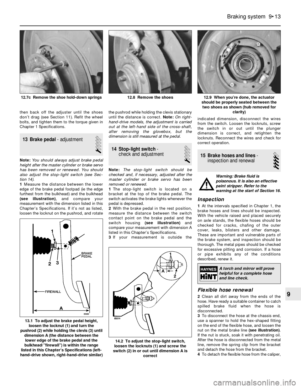
1Measure the distance between the lower
edge of the brake pedal footpad (ie the edge
furthest from the bulkhead) and the bulkhead
(see illustration), and compare your
measurement with the dimension listed in this
Chapter’s Specifications. If it’s not as listed,
loosen the locknut on the pushrod, and rotatethe pushrod while holding the clevis stationary
until the distance is correct. Note:On right-
hand-drive models, the adjustment is carried
out at the left-hand side of the cross-shaft,
after removing the glovebox, but the
dimension is still measured at the pedal.
14 Stop-light switch-
check and adjustment
1
Note:The stop-light switch should be
checked and, if necessary, adjusted after the
master cylinder or brake servo has been
removed or renewed.
1The stop-light switch is located on a
bracket at the top of the brake pedal. The
switch activates the brake lights whenever the
pedal is depressed.
2With the brake pedal in the rest position,
measure the distance between the switch
contact point on the brake pedal and the
switch housing (see illustration)and
compare your measurement with dimension A
listed in this Chapter’s Specifications.
3If your measurement is outside theindicated dimension, disconnect the wires
from the switch. Loosen the locknuts, screw
the switch in or out until the plunger
dimension is correct, and retighten the
locknuts. Reconnect the wires and check for
correct operation.
15 Brake hoses and lines-
inspection and renewal
4
Warning: Brake fluid is
poisonous. It is also an effective
paint stripper. Refer to the
warning at the start of Section 16.
Inspection
1At the intervals specified in Chapter 1, the
brake hoses and lines should be inspected.
With the vehicle raised and placed securely
on axle stands, the flexible hoses should be
checked for cracks, chafing of the outer
cover, leaks, blisters and other damage.
These are important and vulnerable parts of
the brake system, and inspection should be
thorough. The metal pipes should be checked
for excessive pitting and corrosion. If a hose
or pipe exhibits any of the conditions
described, renew it.
Flexible hose renewal
2Clean all dirt away from the ends of the
hose. Have ready a suitable container to catch
spilled brake fluid when the hose is
disconnected.
3To disconnect the hose at the chassis end,
use a spanner to hold the hex-shaped fitting
on the end of the flexible hose, and loosen the
nut on the metal brake line (see illustration).
If the nut is stuck, soak it with penetrating oil.
After the hose is disconnected from the metal
line, remove the spring clip from the bracket
and detach the hose from the bracket.
4To detach the flexible hose from the caliper,
Braking system 9•13
12.9 When you’re done, the actuator
should be properly seated between the
two shoes as shown (hub removed for
clarity)12.8 Remove the shoes12.7c Remove the shoe hold-down springs
14.2 To adjust the stop-light switch,
loosen the locknuts (1) and screw the
switch (2) in or out until dimension A is
correct
13.1 To adjust the brake pedal height,
loosen the locknut (1) and turn the
pushrod (2) while holding the clevis (3) until
dimension A (the distance between the
lower edge of the brake pedal and the
bulkhead/”firewall”) is within the range
listed in this Chapter’s Specifications (left-
hand-drive shown, right-hand-drive similar)
9
A torch and mirror will prove
helpful for a complete hose
and line check.
Page 148 of 228
Bush inspection and renewal
8If the bush is cracked, torn or otherwise
deteriorated, take the arm to a BMW dealer
service department or an engineering works,
and have it pressed out and a new bush
pressed in. Bushes should always be renewed
in pairs (a new bush should be fitted in each
arm, and both bushes should have the same
manufacturer markings). If you’re fitting a new
thrust arm bush, make sure it’s correctly
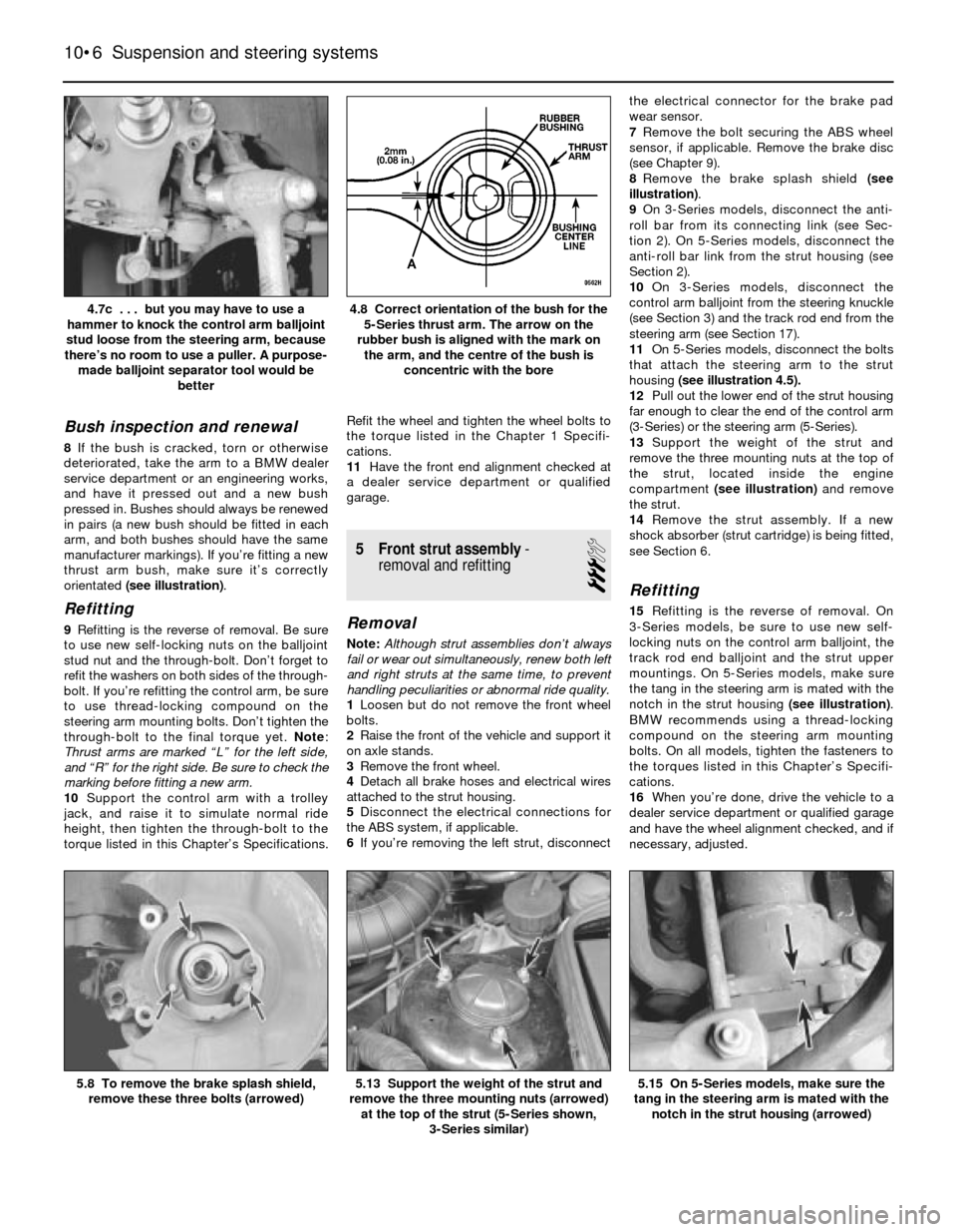
orientated (see illustration).
Refitting
9Refitting is the reverse of removal. Be sure
to use new self-locking nuts on the balljoint
stud nut and the through-bolt. Don’t forget to
refit the washers on both sides of the through-
bolt. If you’re refitting the control arm, be sure
to use thread-locking compound on the
steering arm mounting bolts. Don’t tighten the
through-bolt to the final torque yet. Note:
Thrust arms are marked “L” for the left side,
and “R” for the right side. Be sure to check the
marking before fitting a new arm.
10Support the control arm with a trolley
jack, and raise it to simulate normal ride
height, then tighten the through-bolt to the
torque listed in this Chapter’s Specifications.Refit the wheel and tighten the wheel bolts to
the torque listed in the Chapter 1 Specifi-
cations.
11Have the front end alignment checked at
a dealer service department or qualified
garage.
5 Front strut assembly-
removal and refitting
3
Removal
Note:Although strut assemblies don’t always
fail or wear out simultaneously, renew both left
and right struts at the same time, to prevent
handling peculiarities or abnormal ride quality.
1Loosen but do not remove the front wheel
bolts.
2Raise the front of the vehicle and support it
on axle stands.
3Remove the front wheel.
4Detach all brake hoses and electrical wires
attached to the strut housing.
5Disconnect the electrical connections for
the ABS system, if applicable.
6If you’re removing the left strut, disconnectthe electrical connector for the brake pad
wear sensor.
7Remove the bolt securing the ABS wheel
sensor, if applicable. Remove the brake disc
(see Chapter 9).
8Remove the brake splash shield (see
illustration).
9On 3-Series models, disconnect the anti-
roll bar from its connecting link (see Sec-
tion 2). On 5-Series models, disconnect the
anti-roll bar link from the strut housing (see
Section 2).
10On 3-Series models, disconnect the
control arm balljoint from the steering knuckle
(see Section 3) and the track rod end from the
steering arm (see Section 17).
11On 5-Series models, disconnect the bolts
that attach the steering arm to the strut
housing (see illustration 4.5).
12Pull out the lower end of the strut housing
far enough to clear the end of the control arm
(3-Series) or the steering arm (5-Series).
13Support the weight of the strut and
remove the three mounting nuts at the top of
the strut, located inside the engine
compartment (see illustration)and remove
the strut.
14Remove the strut assembly. If a new
shock absorber (strut cartridge) is being fitted,
see Section 6.
Refitting
15Refitting is the reverse of removal. On
3-Series models, be sure to use new self-
locking nuts on the control arm balljoint, the
track rod end balljoint and the strut upper
mountings. On 5-Series models, make sure
the tang in the steering arm is mated with the
notch in the strut housing (see illustration).
BMW recommends using a thread-locking
compound on the steering arm mounting
bolts. On all models, tighten the fasteners to
the torques listed in this Chapter’s Specifi-
cations.
16When you’re done, drive the vehicle to a
dealer service department or qualified garage
and have the wheel alignment checked, and if
necessary, adjusted.
10•6 Suspension and steering systems
5.15 On 5-Series models, make sure the
tang in the steering arm is mated with the
notch in the strut housing (arrowed)5.13 Support the weight of the strut and
remove the three mounting nuts (arrowed)
at the top of the strut (5-Series shown,
3-Series similar)5.8 To remove the brake splash shield,
remove these three bolts (arrowed)
4.8 Correct orientation of the bush for the
5-Series thrust arm. The arrow on the
rubber bush is aligned with the mark on
the arm, and the centre of the bush is
concentric with the bore4.7c . . . but you may have to use a
hammer to knock the control arm balljoint
stud loose from the steering arm, because
there’s no room to use a puller. A purpose-
made balljoint separator tool would be
better
Page 151 of 228
4On some models, working inside the boot,
you can remove the trim to access the upper
mounting nuts; on later models, you’ll have to
remove the rear seat back to get at the upper
mounting nuts. On Touring (Estate) models,
remove the side backrest and rear seat belt
reels, and unscrew the centring shell on the
wheel arch. On Convertibles, simply remove
the top from the recessed well behind the
passenger compartment, and remove the
small rubber access cover. As you remove the
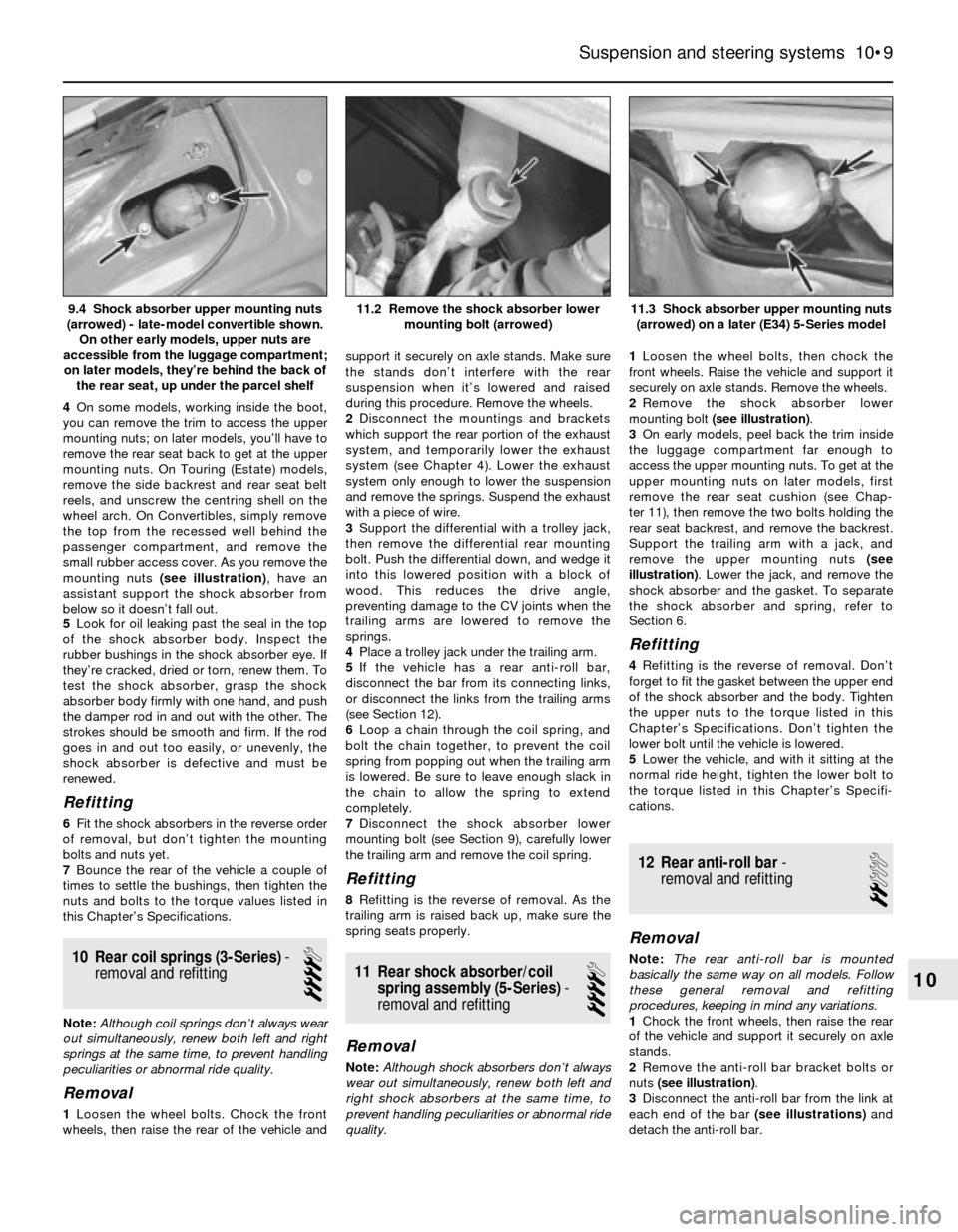
mounting nuts (see illustration), have an
assistant support the shock absorber from
below so it doesn’t fall out.
5Look for oil leaking past the seal in the top
of the shock absorber body. Inspect the
rubber bushings in the shock absorber eye. If
they’re cracked, dried or torn, renew them. To
test the shock absorber, grasp the shock
absorber body firmly with one hand, and push
the damper rod in and out with the other. The
strokes should be smooth and firm. If the rod
goes in and out too easily, or unevenly, the
shock absorber is defective and must be
renewed.
Refitting
6Fit the shock absorbers in the reverse order
of removal, but don’t tighten the mounting
bolts and nuts yet.
7Bounce the rear of the vehicle a couple of
times to settle the bushings, then tighten the
nuts and bolts to the torque values listed in
this Chapter’s Specifications.
10 Rear coil springs (3-Series)-
removal and refitting
4
Note: Although coil springs don’t always wear
out simultaneously, renew both left and right
springs at the same time, to prevent handling
peculiarities or abnormal ride quality.
Removal
1Loosen the wheel bolts. Chock the front
wheels, then raise the rear of the vehicle andsupport it securely on axle stands. Make sure
the stands don’t interfere with the rear
suspension when it’s lowered and raised
during this procedure. Remove the wheels.
2Disconnect the mountings and brackets
which support the rear portion of the exhaust
system, and temporarily lower the exhaust
system (see Chapter 4). Lower the exhaust
system only enough to lower the suspension
and remove the springs. Suspend the exhaust
with a piece of wire.
3Support the differential with a trolley jack,
then remove the differential rear mounting
bolt. Push the differential down, and wedge it
into this lowered position with a block of
wood. This reduces the drive angle,
preventing damage to the CV joints when the
trailing arms are lowered to remove the
springs.
4Place a trolley jack under the trailing arm.
5If the vehicle has a rear anti-roll bar,
disconnect the bar from its connecting links,
or disconnect the links from the trailing arms
(see Section 12).
6Loop a chain through the coil spring, and
bolt the chain together, to prevent the coil
spring from popping out when the trailing arm
is lowered. Be sure to leave enough slack in
the chain to allow the spring to extend
completely.
7Disconnect the shock absorber lower
mounting bolt (see Section 9), carefully lower
the trailing arm and remove the coil spring.
Refitting
8Refitting is the reverse of removal. As the
trailing arm is raised back up, make sure the
spring seats properly.
11 Rear shock absorber/coil
spring assembly (5-Series)-
removal and refitting
4
Removal
Note:Although shock absorbers don’t always
wear out simultaneously, renew both left and
right shock absorbers at the same time, to
prevent handling peculiarities or abnormal ride
quality.1Loosen the wheel bolts, then chock the
front wheels. Raise the vehicle and support it
securely on axle stands. Remove the wheels.
2Remove the shock absorber lower
mounting bolt (see illustration).
3On early models, peel back the trim inside
the luggage compartment far enough to
access the upper mounting nuts. To get at the
upper mounting nuts on later models, first
remove the rear seat cushion (see Chap-
ter 11), then remove the two bolts holding the
rear seat backrest, and remove the backrest.
Support the trailing arm with a jack, and
remove the upper mounting nuts (see
illustration). Lower the jack, and remove the
shock absorber and the gasket. To separate
the shock absorber and spring, refer to
Section 6.
Refitting
4Refitting is the reverse of removal. Don’t
forget to fit the gasket between the upper end
of the shock absorber and the body. Tighten
the upper nuts to the torque listed in this
Chapter’s Specifications. Don’t tighten the
lower bolt until the vehicle is lowered.
5Lower the vehicle, and with it sitting at the
normal ride height, tighten the lower bolt to
the torque listed in this Chapter’s Specifi-
cations.
12 Rear anti-roll bar-
removal and refitting
2
Removal
Note:The rear anti-roll bar is mounted
basically the same way on all models. Follow
these general removal and refitting
procedures, keeping in mind any variations.
1Chock the front wheels, then raise the rear
of the vehicle and support it securely on axle
stands.
2Remove the anti-roll bar bracket bolts or
nuts (see illustration).
3Disconnect the anti-roll bar from the link at
each end of the bar (see illustrations)and
detach the anti-roll bar.
Suspension and steering systems 10•9
11.3 Shock absorber upper mounting nuts
(arrowed) on a later (E34) 5-Series model11.2 Remove the shock absorber lower
mounting bolt (arrowed)9.4 Shock absorber upper mounting nuts
(arrowed) - late-model convertible shown.
On other early models, upper nuts are
accessible from the luggage compartment;
on later models, they’re behind the back of
the rear seat, up under the parcel shelf
10
Page 152 of 228
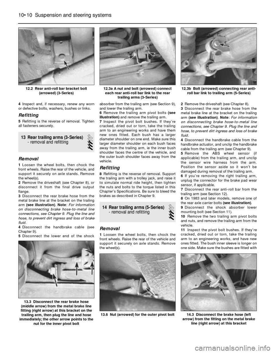
4Inspect and, if necessary, renew any worn
or defective bolts, washers, bushes or links.
Refitting
5Refitting is the reverse of removal. Tighten
all fasteners securely.
13 Rear trailing arms (3-Series)
- removal and refitting
3
Removal
1Loosen the wheel bolts, then chock the
front wheels. Raise the rear of the vehicle, and
support it securely on axle stands. Remove
the wheel(s).
2Remove the driveshaft (see Chapter 8), or
disconnect it from the final drive output
flange.
3Disconnect the rear brake hose from the
metal brake line at the bracket on the trailing
arm (see illustration). Note: For information
on disconnecting brake hose-to-metal line
connections, see Chapter 9. Plug the line and
hose, to prevent dirt ingress and loss of brake
fluid.
4Disconnect the handbrake cable (see
Chapter 9).
5Disconnect the lower end of the shockabsorber from the trailing arm (see Section 9),
and lower the trailing arm.
6Remove the trailing arm pivot bolts (see
illustration)and remove the trailing arm.
7Inspect the pivot bolt bushes. If they’re
cracked, dried out or torn, take the trailing
arm to an engineering works and have them
new ones fitted. Each bush has a larger
diameter shoulder on one end. Make sure this
larger diameter shoulder on each bush faces
away from the trailing arm, ie the inner bush
shoulder faces the centre of the vehicle, and
the outer bush shoulder faces away from the
vehicle.Refitting
8Refitting is the reverse of removal. Support
the trailing arm with a trolley jack, and raise it
to simulate normal ride height, then tighten
the nuts and bolts to the torque listed in this
Chapter’s Specifications. Be sure to bleed the
brakes as described in Chapter 9.
14 Rear trailing arms (5-Series)
- removal and refitting
3
Removal
1Loosen the wheel bolts, then chock the
front wheels. Raise the rear of the vehicle and
support it securely on axle stands. Remove
the wheel(s).2Remove the driveshaft (see Chapter 8).
3Disconnect the rear brake hose from the
metal brake line at the bracket on the trailing
arm (see illustration). Note: For information
on disconnecting brake hose-to-metal line
connections, see Chapter 9. Plug the line and
hose, to prevent dirt ingress and loss of brake
fluid.
4Disconnect the handbrake cable from the
handbrake actuator, and unclip the handbrake
cable from the trailing arm (see Chapter 9).
5Remove the ABS wheel sensor (if
applicable) from the trailing arm, and unclip
the sensor wire harness from the arm.
Position the sensor aside so it won’t be
damaged during removal of the trailing arm.
6If you’re removing the right trailing arm,
unplug the connector for the brake pad wear
sensor, if applicable.
7Disconnect the rear anti-roll bar from the
trailing arm (see Section 12).
8On 1983 and later models, remove one of
the rear axle carrier bolts (see illustration).
9Disconnect the shock absorber lower
mounting bolt (see Section 11).
10Remove the two trailing arm pivot bolts
and nuts, and remove the trailing arm from the
vehicle.
11Inspect the pivot bolt bushes. If they’re
cracked, dried out or torn, take the trailing
arm to an engineering works, and have new
ones fitted. The bush inner sleeve is longer on
one side. Make sure the bushes are fitted with
10•10 Suspension and steering systems
14.3 Disconnect the brake hose (left
arrow) from the fitting on the metal brake
line (right arrow) at this bracket13.6 Nut (arrowed) for the outer pivot bolt
13.3 Disconnect the rear brake hose
(middle arrow) from the metal brake line
fitting (right arrow) at this bracket on the
trailing arm, then plug the line and hose
immediately; the other arrow points to the
nut for the inner pivot bolt
12.3b Bolt (arrowed) connecting rear anti-
roll bar link to trailing arm (5-Series)12.3a A nut and bolt (arrowed) connect
each rear anti-roll bar link to the rear
trailing arms (3-Series)12.2 Rear anti-roll bar bracket bolt
(arrowed) (3-Series)