low beam BMW 3 SERIES 1983 E30 Workshop Manual
[x] Cancel search | Manufacturer: BMW, Model Year: 1983, Model line: 3 SERIES, Model: BMW 3 SERIES 1983 E30Pages: 228, PDF Size: 7.04 MB
Page 114 of 228
7 Ignition timing (TCI system)-
check and adjustment
4
Warning: Keep hands, equipment
and wires well clear of the
viscous cooling fan during
adjustment of the ignition timing.
Note:This Section describes the procedure
for checking and adjusting the ignition timing
on engines fitted with the TCI system. On
engines fitted with the Motronic engine
management system, the ignition timing is
controlled by the electronic control unit, and
no adjustment is possible. The timing can be
checked using the following procedure, but no
ignition timing values were available at the
time of writing. If the timing is thought to be
incorrect, refer to a BMW dealer.
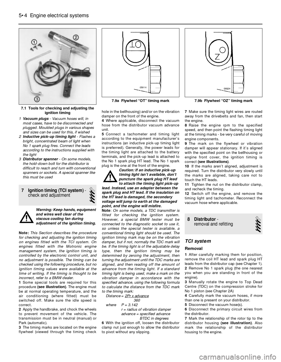
1Some special tools are required for this
procedure (see illustration). The engine must
be at normal operating temperature, and the
air conditioning (where fitted) must be
switched off. Make sure the idle speed is
correct.
2Apply the handbrake, and chock the wheels
to prevent movement of the vehicle. The
transmission must be in neutral (manual) or
Park (automatic).
3The timing marks are located on the engine
flywheel (viewed through the timing checkhole in the bellhousing) and/or on the vibration
damper on the front of the engine.
4Where applicable, disconnect the vacuum
hose from the distributor vacuum advance
unit.
5Connect a tachometer and timing light
according to the equipment manufacturer’s
instructions (an inductive pick-up timing light
is preferred). Generally, the power leads for
the timing light are attached to the battery
terminals, and the pick-up lead is attached to
the No 1 spark plug HT lead. The No 1 spark
plug is the one at the front of the engine.
Caution: If an inductive pick-up
timing light isn’t available, don’t
puncture the spark plug HT lead
to attach the timing light pick-up
lead. Instead, use an adapter between the
spark plug and HT lead. If the insulation on
the HT lead is damaged, the secondary
voltage will jump to earth at the damaged
point, and the engine will misfire.
Note:On some models, a TDC transmitter is
fitted for checking the ignition system.
However, a special BMW tester must be
connected to the diagnostic socket to use it,
so unless the special tester is available, a
conventional timing light should be used. The
ignition timing mark may be on the vibration
damper, but if not, normally the TDC mark will
be. If the timing light is of the adjustable delay
type, then the ignition timing may be
determined by zeroing the adjustment, then
turning the adjustment until the TDC marks are
aligned, and then reading off the amount of
advance from the timing light. If a standard
timing light is being used, make a mark on the
vibration damper in accordance with the
specified advance, using the following formula
to calculate the distance from the TDC mark
to the timing mark:
Distance = 2Pr x advance
360
where P = 3.142
r = radius of vibration damper
advance = specified advance
BTDC in degrees
6With the ignition off, loosen the distributor
clamp nut just enough to allow the distributor
to pivot without any slipping.7Make sure the timing light wires are routed
away from the drivebelts and fan, then start
the engine.
8Raise the engine rpm to the specified
speed, and then point the flashing timing light
at the timing marks - be very careful of moving
engine components.
9The mark on the flywheel or vibration
damper will appear stationary. If it’s aligned
with the specified point on the bellhousing or
engine front cover, the ignition timing is
correct (see illustrations).
10If the marks aren’t aligned, adjustment is
required. Turn the distributor very slowly until
the marks are aligned, taking care not to
touch the HT leads.
11Tighten the nut on the distributor clamp,
and recheck the timing.
12Switch off the engine, and remove the
timing light and tachometer. Reconnect the
vacuum hose where applicable.
8 Distributor-
removal and refitting
4
TCI system
Removal
1After carefully marking them for position,
remove the coil HT lead and spark plug HT
leads from the distributor cap (see Chapter 1).
2Remove No 1 spark plug (the one nearest
you when you are standing in front of the
engine).
3Manually rotate the engine to Top Dead
Centre (TDC) on the compression stroke for
No 1 piston (see Chapter 2A)
4Carefully mark the vacuum hoses, if more
than one is present on your distributor.
5Disconnect the vacuum hose(s).
6Disconnect the primary circuit wires from
the distributor.
7Mark the relationship of the rotor tip to the
distributor housing (see illustration). Also
mark the relationship of the distributor
housing to the engine.
5•4 Engine electrical systems
7.1 Tools for checking and adjusting the
ignition timing
1Vacuum plugs- Vacuum hoses will, in
most cases, have to be disconnected and
plugged. Moulded plugs in various shapes
and sizes can be used for this, if wished
2Inductive pick-up timing light- Flashes a
bright, concentrated beam of light when
No 1 spark plug fires. Connect the leads
according to the instructions supplied with
the light
3Distributor spanner - On some models,
the hold-down bolt for the distributor is
difficult to reach and turn with conventional
spanners or sockets. A special spanner like
this must be used
7.9a Flywheel “OT” timing mark 7.9b Flywheel “OZ” timing mark
Page 173 of 228
SI board is a self-contained computer which
includes a chip and batteries.
The rechargeable SI board nickel cadmium
(nicad) batteries maintain power to the
computer memory in the event of a power
drop (such as during starting) or complete
power loss (such as a dead or disconnected
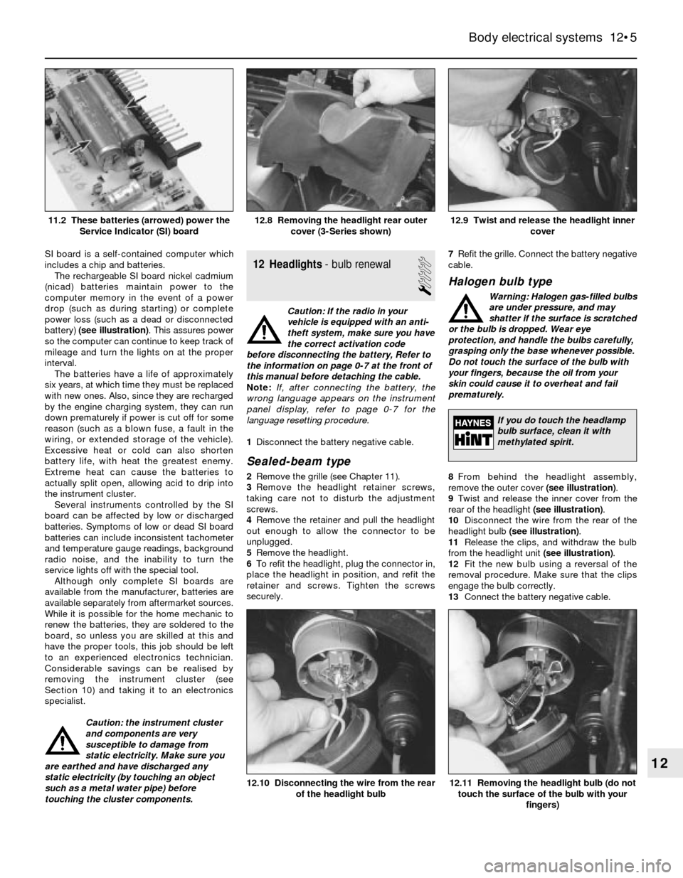
battery) (see illustration). This assures power
so the computer can continue to keep track of
mileage and turn the lights on at the proper
interval.
The batteries have a life of approximately
six years, at which time they must be replaced
with new ones. Also, since they are recharged
by the engine charging system, they can run
down prematurely if power is cut off for some
reason (such as a blown fuse, a fault in the
wiring, or extended storage of the vehicle).
Excessive heat or cold can also shorten
battery life, with heat the greatest enemy.
Extreme heat can cause the batteries to
actually split open, allowing acid to drip into
the instrument cluster.
Several instruments controlled by the SI
board can be affected by low or discharged
batteries. Symptoms of low or dead SI board
batteries can include inconsistent tachometer
and temperature gauge readings, background
radio noise, and the inability to turn the
service lights off with the special tool.
Although only complete SI boards are
available from the manufacturer, batteries are
available separately from aftermarket sources.
While it is possible for the home mechanic to
renew the batteries, they are soldered to the
board, so unless you are skilled at this and
have the proper tools, this job should be left
to an experienced electronics technician.
Considerable savings can be realised by
removing the instrument cluster (see
Section 10) and taking it to an electronics
specialist.
Caution: the instrument cluster
and components are very
susceptible to damage from
static electricity. Make sure you
are earthed and have discharged any
static electricity (by touching an object
such as a metal water pipe) before
touching the cluster components.12 Headlights- bulb renewal
1
Caution: If the radio in your
vehicle is equipped with an anti-
theft system, make sure you have
the correct activation code
before disconnecting the battery, Refer to
the information on page 0-7 at the front of
this manual before detaching the cable.
Note: If, after connecting the battery, the
wrong language appears on the instrument
panel display, refer to page 0-7 for the
language resetting procedure.
1Disconnect the battery negative cable.
Sealed-beam type
2Remove the grille (see Chapter 11).
3Remove the headlight retainer screws,
taking care not to disturb the adjustment
screws.
4Remove the retainer and pull the headlight
out enough to allow the connector to be
unplugged.
5Remove the headlight.
6To refit the headlight, plug the connector in,
place the headlight in position, and refit the
retainer and screws. Tighten the screws
securely.7Refit the grille. Connect the battery negative
cable.
Halogen bulb type
Warning: Halogen gas-filled bulbs
are under pressure, and may
shatter if the surface is scratched
or the bulb is dropped. Wear eye
protection, and handle the bulbs carefully,
grasping only the base whenever possible.
Do not touch the surface of the bulb with
your fingers, because the oil from your
skin could cause it to overheat and fail
prematurely.
8From behind the headlight assembly,
remove the outer cover (see illustration).
9Twist and release the inner cover from the
rear of the headlight (see illustration).
10Disconnect the wire from the rear of the
headlight bulb (see illustration).
11Release the clips, and withdraw the bulb
from the headlight unit (see illustration).
12Fit the new bulb using a reversal of the
removal procedure. Make sure that the clips
engage the bulb correctly.
13Connect the battery negative cable.
Body electrical systems 12•5
12.9 Twist and release the headlight inner
cover12.8 Removing the headlight rear outer
cover (3-Series shown)11.2 These batteries (arrowed) power the
Service Indicator (SI) board
12.11 Removing the headlight bulb (do not
touch the surface of the bulb with your
fingers)12.10 Disconnecting the wire from the rear
of the headlight bulb
12
If you do touch the headlamp
bulb surface, clean it with
methylated spirit.
Page 174 of 228
13 Headlights- adjustment
2
Note:The headlights must be aimed correctly.
If adjusted incorrectly, they could momentarily
blind the driver of an oncoming vehicle and
cause a serious accident, or seriously reduce
your ability to see the road. The headlights
should be checked for proper aim every
12 months (as is done during the MOT test),
and any time a new headlight is fitted or front-
end body work is performed. It should be
emphasised that the following procedure will
only provide a temporary setting until the
headlights can be adjusted by a properly-
equipped garage.
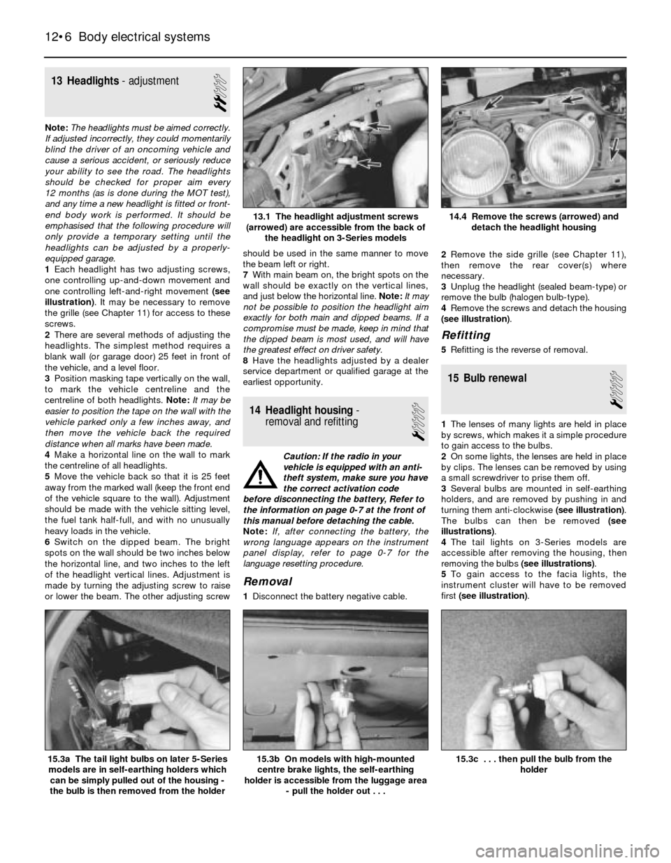
1Each headlight has two adjusting screws,
one controlling up-and-down movement and
one controlling left-and-right movement (see
illustration). It may be necessary to remove
the grille (see Chapter 11) for access to these
screws.
2There are several methods of adjusting the
headlights. The simplest method requires a
blank wall (or garage door) 25 feet in front of
the vehicle, and a level floor.
3Position masking tape vertically on the wall,
to mark the vehicle centreline and the
centreline of both headlights. Note:It may be
easier to position the tape on the wall with the
vehicle parked only a few inches away, and
then move the vehicle back the required
distance when all marks have been made.
4Make a horizontal line on the wall to mark
the centreline of all headlights.
5Move the vehicle back so that it is 25 feet
away from the marked wall (keep the front end
of the vehicle square to the wall). Adjustment
should be made with the vehicle sitting level,
the fuel tank half-full, and with no unusually
heavy loads in the vehicle.
6Switch on the dipped beam. The bright
spots on the wall should be two inches below
the horizontal line, and two inches to the left
of the headlight vertical lines. Adjustment is
made by turning the adjusting screw to raise
or lower the beam. The other adjusting screwshould be used in the same manner to move
the beam left or right.
7With main beam on, the bright spots on the
wall should be exactly on the vertical lines,
and just below the horizontal line. Note:It may
not be possible to position the headlight aim
exactly for both main and dipped beams. If a
compromise must be made, keep in mind that
the dipped beam is most used, and will have
the greatest effect on driver safety.
8Have the headlights adjusted by a dealer
service department or qualified garage at the
earliest opportunity.
14 Headlight housing-
removal and refitting
1
Caution: If the radio in your
vehicle is equipped with an anti-
theft system, make sure you have
the correct activation code
before disconnecting the battery, Refer to
the information on page 0-7 at the front of
this manual before detaching the cable.
Note: If, after connecting the battery, the
wrong language appears on the instrument
panel display, refer to page 0-7 for the
language resetting procedure.
Removal
1Disconnect the battery negative cable.2Remove the side grille (see Chapter 11),
then remove the rear cover(s) where
necessary.
3Unplug the headlight (sealed beam-type) or
remove the bulb (halogen bulb-type).
4Remove the screws and detach the housing
(see illustration).
Refitting
5Refitting is the reverse of removal.
15 Bulb renewal
1
1The lenses of many lights are held in place
by screws, which makes it a simple procedure
to gain access to the bulbs.
2On some lights, the lenses are held in place
by clips. The lenses can be removed by using
a small screwdriver to prise them off.
3Several bulbs are mounted in self-earthing
holders, and are removed by pushing in and
turning them anti-clockwise (see illustration).
The bulbs can then be removed (see
illustrations).
4The tail lights on 3-Series models are
accessible after removing the housing, then
removing the bulbs (see illustrations).
5To gain access to the facia lights, the
instrument cluster will have to be removed
first (see illustration).
12•6 Body electrical systems
15.3c . . . then pull the bulb from the
holder15.3b On models with high-mounted
centre brake lights, the self-earthing
holder is accessible from the luggage area
- pull the holder out . . .15.3a The tail light bulbs on later 5-Series
models are in self-earthing holders which
can be simply pulled out of the housing -
the bulb is then removed from the holder
14.4 Remove the screws (arrowed) and
detach the headlight housing13.1 The headlight adjustment screws
(arrowed) are accessible from the back of
the headlight on 3-Series models
Page 220 of 228
REF•20Glossary of Technical Terms
A
ABS (Anti-lock brake system)A system,
usually electronically controlled, that senses
incipient wheel lockup during braking and
relieves hydraulic pressure at wheels that are
about to skid.
Air bag An inflatable bag hidden in the
steering wheel (driver’s side) or the dash or
glovebox (passenger side). In a head-on
collision, the bags inflate, preventing the
driver and front passenger from being thrown
forward into the steering wheel or windscreen.
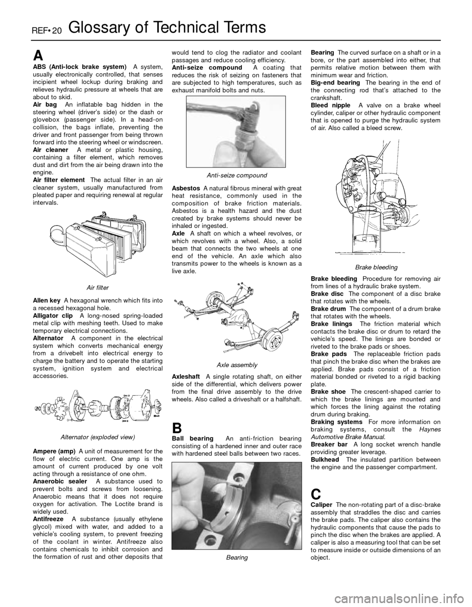
Air cleanerA metal or plastic housing,
containing a filter element, which removes
dust and dirt from the air being drawn into the
engine.
Air filter elementThe actual filter in an air
cleaner system, usually manufactured from
pleated paper and requiring renewal at regular
intervals.
Allen keyA hexagonal wrench which fits into
a recessed hexagonal hole.
Alligator clipA long-nosed spring-loaded
metal clip with meshing teeth. Used to make
temporary electrical connections.
AlternatorA component in the electrical
system which converts mechanical energy
from a drivebelt into electrical energy to
charge the battery and to operate the starting
system, ignition system and electrical
accessories.
Ampere (amp)A unit of measurement for the
flow of electric current. One amp is the
amount of current produced by one volt
acting through a resistance of one ohm.
Anaerobic sealerA substance used to
prevent bolts and screws from loosening.
Anaerobic means that it does not require
oxygen for activation. The Loctite brand is
widely used.
AntifreezeA substance (usually ethylene
glycol) mixed with water, and added to a
vehicle’s cooling system, to prevent freezing
of the coolant in winter. Antifreeze also
contains chemicals to inhibit corrosion and
the formation of rust and other deposits thatwould tend to clog the radiator and coolant
passages and reduce cooling efficiency.
Anti-seize compoundA coating that
reduces the risk of seizing on fasteners that
are subjected to high temperatures, such as
exhaust manifold bolts and nuts.
AsbestosA natural fibrous mineral with great
heat resistance, commonly used in the
composition of brake friction materials.
Asbestos is a health hazard and the dust
created by brake systems should never be
inhaled or ingested.
AxleA shaft on which a wheel revolves, or
which revolves with a wheel. Also, a solid
beam that connects the two wheels at one
end of the vehicle. An axle which also
transmits power to the wheels is known as a
live axle.
AxleshaftA single rotating shaft, on either
side of the differential, which delivers power
from the final drive assembly to the drive
wheels. Also called a driveshaft or a halfshaft.
BBall bearingAn anti-friction bearing
consisting of a hardened inner and outer race
with hardened steel balls between two races.BearingThe curved surface on a shaft or in a
bore, or the part assembled into either, that
permits relative motion between them with
minimum wear and friction.
Big-end bearingThe bearing in the end of
the connecting rod that’s attached to the
crankshaft.
Bleed nippleA valve on a brake wheel
cylinder, caliper or other hydraulic component
that is opened to purge the hydraulic system
of air. Also called a bleed screw.
Brake bleedingProcedure for removing air
from lines of a hydraulic brake system.
Brake discThe component of a disc brake
that rotates with the wheels.
Brake drumThe component of a drum brake
that rotates with the wheels.
Brake liningsThe friction material which
contacts the brake disc or drum to retard the
vehicle’s speed. The linings are bonded or
riveted to the brake pads or shoes.
Brake padsThe replaceable friction pads
that pinch the brake disc when the brakes are
applied. Brake pads consist of a friction
material bonded or riveted to a rigid backing
plate.
Brake shoeThe crescent-shaped carrier to
which the brake linings are mounted and
which forces the lining against the rotating
drum during braking.
Braking systemsFor more information on
braking systems, consult the Haynes
Automotive Brake Manual.
Breaker barA long socket wrench handle
providing greater leverage.
BulkheadThe insulated partition between
the engine and the passenger compartment.
CCaliperThe non-rotating part of a disc-brake
assembly that straddles the disc and carries
the brake pads. The caliper also contains the
hydraulic components that cause the pads to
pinch the disc when the brakes are applied. A
caliper is also a measuring tool that can be set
to measure inside or outside dimensions of an
object.
Brake bleeding
Bearing
Axle assembly
Anti-seize compound
Alternator (exploded view)
Air filter
Page 223 of 228
REF•23
REF
Glossary of Technical Terms
JJump startStarting the engine of a vehicle
with a discharged or weak battery by
attaching jump leads from the weak battery to
a charged or helper battery.
LLoad Sensing Proportioning Valve (LSPV)A
brake hydraulic system control valve that
works like a proportioning valve, but also
takes into consideration the amount of weight
carried by the rear axle.
LocknutA nut used to lock an adjustment
nut, or other threaded component, in place.
For example, a locknut is employed to keep
the adjusting nut on the rocker arm in
position.
LockwasherA form of washer designed to
prevent an attaching nut from working loose.
MMacPherson strutA type of front
suspension system devised by Earle
MacPherson at Ford of England. In its original
form, a simple lateral link with the anti-roll bar
creates the lower control arm. A long strut - an
integral coil spring and shock absorber - is
mounted between the body and the steering
knuckle. Many modern so-called MacPherson
strut systems use a conventional lower A-arm
and don’t rely on the anti-roll bar for location.
MultimeterAn electrical test instrument with
the capability to measure voltage, current and
resistance.
NNOxOxides of Nitrogen. A common toxic
pollutant emitted by petrol and diesel engines
at higher temperatures.
OOhmThe unit of electrical resistance. One
volt applied to a resistance of one ohm will
produce a current of one amp.
OhmmeterAn instrument for measuring
electrical resistance.
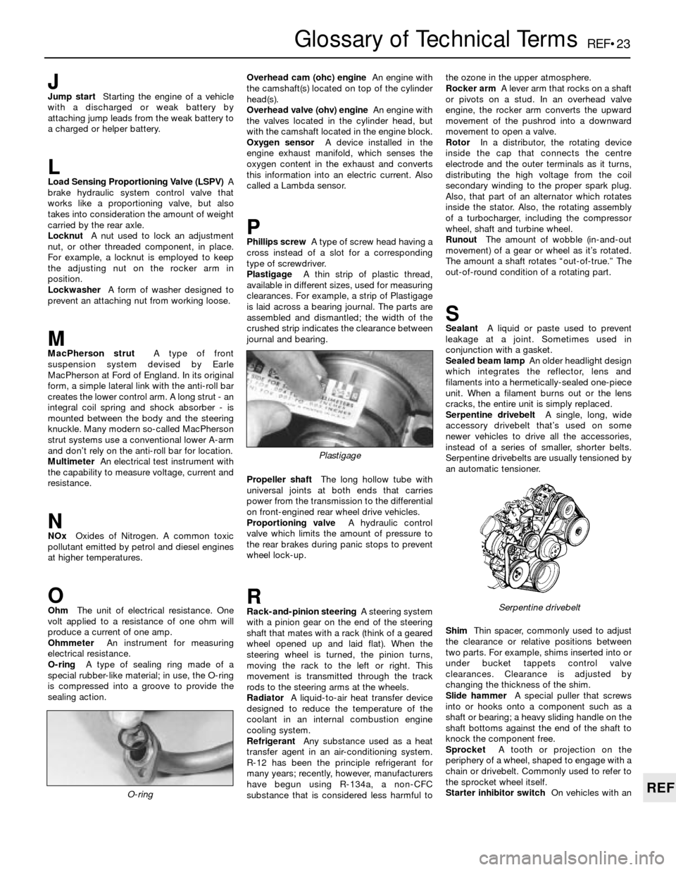
O-ringA type of sealing ring made of a
special rubber-like material; in use, the O-ring
is compressed into a groove to provide the
sealing action.Overhead cam (ohc) engineAn engine with
the camshaft(s) located on top of the cylinder
head(s).
Overhead valve (ohv) engineAn engine with
the valves located in the cylinder head, but
with the camshaft located in the engine block.
Oxygen sensorA device installed in the
engine exhaust manifold, which senses the
oxygen content in the exhaust and converts
this information into an electric current. Also
called a Lambda sensor.
PPhillips screwA type of screw head having a
cross instead of a slot for a corresponding
type of screwdriver.
PlastigageA thin strip of plastic thread,
available in different sizes, used for measuring
clearances. For example, a strip of Plastigage
is laid across a bearing journal. The parts are
assembled and dismantled; the width of the
crushed strip indicates the clearance between
journal and bearing.
Propeller shaftThe long hollow tube with
universal joints at both ends that carries
power from the transmission to the differential
on front-engined rear wheel drive vehicles.
Proportioning valveA hydraulic control
valve which limits the amount of pressure to
the rear brakes during panic stops to prevent
wheel lock-up.
RRack-and-pinion steeringA steering system
with a pinion gear on the end of the steering
shaft that mates with a rack (think of a geared
wheel opened up and laid flat). When the
steering wheel is turned, the pinion turns,
moving the rack to the left or right. This
movement is transmitted through the track
rods to the steering arms at the wheels.
RadiatorA liquid-to-air heat transfer device
designed to reduce the temperature of the
coolant in an internal combustion engine
cooling system.
RefrigerantAny substance used as a heat
transfer agent in an air-conditioning system.
R-12 has been the principle refrigerant for
many years; recently, however, manufacturers
have begun using R-134a, a non-CFC
substance that is considered less harmful tothe ozone in the upper atmosphere.
Rocker armA lever arm that rocks on a shaft
or pivots on a stud. In an overhead valve
engine, the rocker arm converts the upward
movement of the pushrod into a downward
movement to open a valve.
RotorIn a distributor, the rotating device
inside the cap that connects the centre
electrode and the outer terminals as it turns,
distributing the high voltage from the coil
secondary winding to the proper spark plug.
Also, that part of an alternator which rotates
inside the stator. Also, the rotating assembly
of a turbocharger, including the compressor
wheel, shaft and turbine wheel.
RunoutThe amount of wobble (in-and-out
movement) of a gear or wheel as it’s rotated.
The amount a shaft rotates “out-of-true.” The
out-of-round condition of a rotating part.
SSealantA liquid or paste used to prevent
leakage at a joint. Sometimes used in
conjunction with a gasket.
Sealed beam lampAn older headlight design
which integrates the reflector, lens and
filaments into a hermetically-sealed one-piece
unit. When a filament burns out or the lens
cracks, the entire unit is simply replaced.
Serpentine drivebeltA single, long, wide
accessory drivebelt that’s used on some
newer vehicles to drive all the accessories,
instead of a series of smaller, shorter belts.
Serpentine drivebelts are usually tensioned by
an automatic tensioner.
ShimThin spacer, commonly used to adjust
the clearance or relative positions between
two parts. For example, shims inserted into or
under bucket tappets control valve
clearances. Clearance is adjusted by
changing the thickness of the shim.
Slide hammerA special puller that screws
into or hooks onto a component such as a
shaft or bearing; a heavy sliding handle on the
shaft bottoms against the end of the shaft to
knock the component free.
SprocketA tooth or projection on the
periphery of a wheel, shaped to engage with a
chain or drivebelt. Commonly used to refer to
the sprocket wheel itself.
Starter inhibitor switchOn vehicles with an
O-ring
Serpentine drivebelt
Plastigage