Pulley BMW 3 SERIES 1984 E30 User Guide
[x] Cancel search | Manufacturer: BMW, Model Year: 1984, Model line: 3 SERIES, Model: BMW 3 SERIES 1984 E30Pages: 228, PDF Size: 7.04 MB
Page 48 of 228
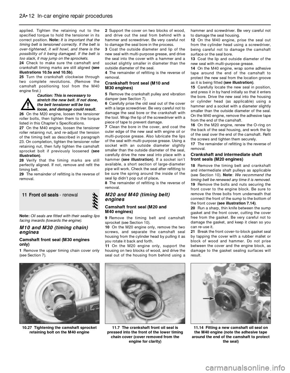
applied. Tighten the retaining nut to the
specified torque to hold the tensioner in its
correct position. Note:It is important that the
timing belt is tensioned correctly. If the belt is
over-tightened, it will howl, and there is the
possibility of it being damaged. If the belt is
too slack, it may jump on the sprockets.
24Check to make sure the camshaft and
crankshaft timing marks are still aligned(see
illustrations 10.5a and 10.5b).
25Turn the crankshaft clockwise through
two complete revolutions. (Remove the
camshaft positioning tool from the M40
engine first.)
Caution: This is necessary to
stretch the new belt. If not done,
the belt tensioner will be too
loose, and damage could result.
26On the M20 engine, loosen the tensioner
roller bolts, then tighten them to the torque
listed in this Chapter’s Specifications.
27On the M40 engine, loosen the tensioner
roller retaining nut, and re-adjust the tension
of the timing belt as described in paragraph
23. On completion, tighten the tensioner roller
retaining nut, then fully tighten the camshaft
sprocket bolt if previously loosened (see
illustration).
28Verify that the timing marks are still
perfectly aligned. If not, remove and refit the
timing belt.
29The remainder of refitting is the reverse of
removal.
11 Front oil seals- renewal
5
Note:Oil seals are fitted with their sealing lips
facing inwards (towards the engine).
M10 and M30 (timing chain)
engines
Camshaft front seal (M30 engines
only)
1Remove the upper timing chain cover only
(see Section 7).2Support the cover on two blocks of wood,
and drive out the seal from behind with a
hammer and screwdriver. Be very careful not
to damage the seal bore in the process.
3Coat the outside diameter and lip of the
new seal with multi-purpose grease, and drive
the seal into the cover with a hammer and a
socket slightly smaller in diameter than the
outside diameter of the seal.
4The remainder of refitting is the reverse of
removal.
Crankshaft front seal (M10 and
M30 engines)
5Remove the crankshaft pulley and vibration
damper (see Section 7).
6Carefully prise the old seal out of the cover
with a large screwdriver. Be very careful not to
damage the seal bore or the crankshaft with
the tool. Wrap the tip of the screwdriver with a
piece of tape to prevent damage.
7Clean the bore in the cover, and coat the
outer edge of the new seal with engine oil or
multi-purpose grease. Also lubricate the lips
of the seal with multi-purpose grease. Using a
socket with an outside diameter slightly
smaller than the outside diameter of the seal,
carefully drive the new seal into place with a
hammer (see illustration). If a socket isn’t
available, a short section of large-diameter
pipe will work. Check the seal after refitting to
be sure the spring around the inside of the
seal lip didn’t pop out of place.
8The remainder of refitting is the reverse of
removal.
M20 and M40 (timing belt)
engines
Camshaft front seal (M20 and
M40 engines)
9Remove the timing belt and camshaft
sprocket (see Section 10).
10On the M20 engine only, remove the two
screws, and separate the camshaft seal
housing from the cylinder head by pulling it as
you rotate it back and forth.
11On the M20 engine only, support the
housing on two blocks of wood, and drive the
seal out of the housing from behind using ahammer and screwdriver. Be very careful not
to damage the seal housing.
12On the M40 engine, prise the seal out
from the cylinder head using a screwdriver,
being careful not to damage the camshaft
surface or the seal bore.
13Coat the lip and outside diameter of the
new seal with multi-purpose grease.
14On the M40 engine, wrap some adhesive
tape around the end of the camshaft to
protect the new seal from the location groove
as it is being fitted (see illustration).
15Carefully locate the new seal in position,
and press it in by hand initially so that it enters
the bore. Drive the new seal into the housing
or cylinder head (as applicable) using a
hammer and a socket with a diameter slightly
smaller than the outside diameter of the seal.
On the M40 engine, remove the adhesive tape
from the end of the camshaft.
16On the M20 engine, renew the O-ring on
the back of the seal housing, and work the lip
of the seal over the end of the camshaft. Refit
the screws and tighten them securely.
17The remainder of refitting is the reverse of
removal.
Crankshaft and intermediate shaft
front seals (M20 engines)
18Remove the timing belt and crankshaft
and intermediate shaft pulleys as applicable
(see Section 10). Note:We recommend the
timing belt be renewed any time it is removed.
19Remove the bolts and nuts securing the
front cover to the engine block. Be sure to
remove the three bolts from underneath that
connect the front of the sump to the bottom of
the front cover (see illustration 7.14).
20Run a sharp, thin knife between the sump
gasket and the front cover, cutting the cover
free from the gasket. Be very careful not to
damage the gasket, and keep it clean so you
can re-use it.
21Break the front cover-to-block gasket seal
by tapping the cover with a rubber mallet or
block of wood and hammer. Do not prise
between the cover and the engine block, as
damage to the gasket sealing surfaces will
result.
2A•12 In-car engine repair procedures
11.14 Fitting a new camshaft oil seal on
the M40 engine (note the adhesive tape
around the end of the camshaft to protect
the seal)11.7 The crankshaft front oil seal is
pressed into the front of the lower timing
chain cover (cover removed from the
engine for clarity)10.27 Tightening the camshaft sprocket
retaining bolt on the M40 engine
Page 54 of 228
26Refit the cover plate and tighten the bolts
to the specified torque.
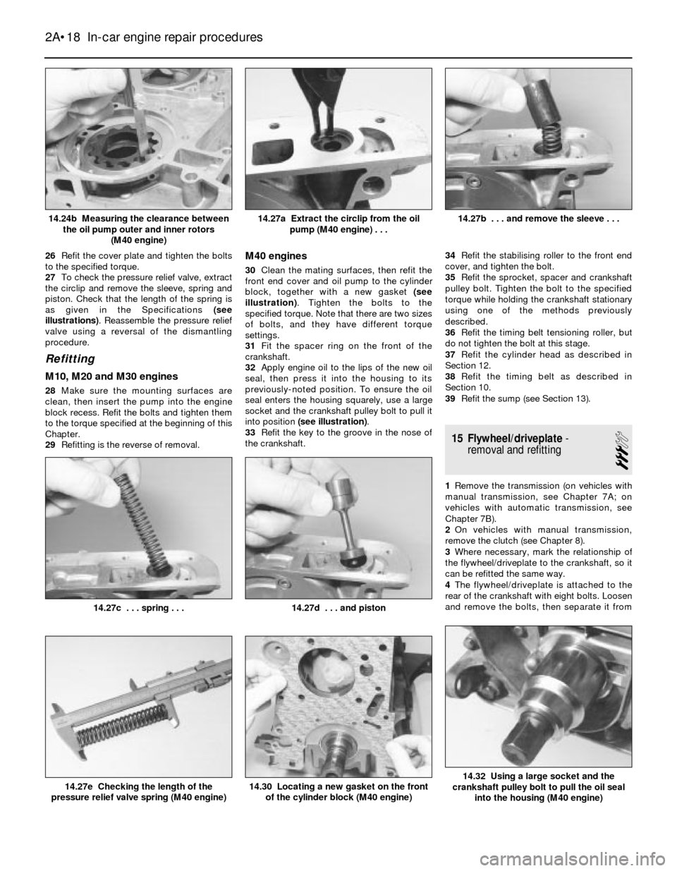
27To check the pressure relief valve, extract
the circlip and remove the sleeve, spring and
piston. Check that the length of the spring is
as given in the Specifications (see
illustrations). Reassemble the pressure relief
valve using a reversal of the dismantling
procedure.
Refitting
M10, M20 and M30 engines
28Make sure the mounting surfaces are
clean, then insert the pump into the engine
block recess. Refit the bolts and tighten them
to the torque specified at the beginning of this
Chapter.
29Refitting is the reverse of removal.
M40 engines
30Clean the mating surfaces, then refit the
front end cover and oil pump to the cylinder
block, together with a new gasket (see
illustration). Tighten the bolts to the
specified torque. Note that there are two sizes
of bolts, and they have different torque
settings.
31Fit the spacer ring on the front of the
crankshaft.
32Apply engine oil to the lips of the new oil
seal, then press it into the housing to its
previously-noted position. To ensure the oil
seal enters the housing squarely, use a large
socket and the crankshaft pulley bolt to pull it
into position (see illustration).
33Refit the key to the groove in the nose of
the crankshaft.34Refit the stabilising roller to the front end
cover, and tighten the bolt.
35Refit the sprocket, spacer and crankshaft
pulley bolt. Tighten the bolt to the specified
torque while holding the crankshaft stationary
using one of the methods previously
described.
36Refit the timing belt tensioning roller, but
do not tighten the bolt at this stage.
37Refit the cylinder head as described in
Section 12.
38Refit the timing belt as described in
Section 10.
39Refit the sump (see Section 13).
15 Flywheel/driveplate-
removal and refitting
3
1Remove the transmission (on vehicles with
manual transmission, see Chapter 7A; on
vehicles with automatic transmission, see
Chapter 7B).
2On vehicles with manual transmission,
remove the clutch (see Chapter 8).
3Where necessary, mark the relationship of
the flywheel/driveplate to the crankshaft, so it
can be refitted the same way.
4The flywheel/driveplate is attached to the
rear of the crankshaft with eight bolts. Loosen
and remove the bolts, then separate it from
2A•18 In-car engine repair procedures
14.32 Using a large socket and the
crankshaft pulley bolt to pull the oil seal
into the housing (M40 engine)14.30 Locating a new gasket on the front
of the cylinder block (M40 engine)14.27e Checking the length of the
pressure relief valve spring (M40 engine)
14.27d . . . and piston14.27c . . . spring . . .
14.27b . . . and remove the sleeve . . .14.27a Extract the circlip from the oil
pump (M40 engine) . . .14.24b Measuring the clearance between
the oil pump outer and inner rotors
(M40 engine)
Page 83 of 228
3-Series models
14Remove the radiator grille assembly (see
Chapter 11).
15Unbolt and remove the fan bracket and
shroud assembly from the radiator (see
Section 5).
16Remove the radiator (see Section 4).
17Unbolt the air conditioning condenser
mounting bolts, where applicable. Do not
remove the condenser or disconnect any
refrigerant lines from the condenser.
18Carefully pull the condenser back towards
the engine, slightly, to gain access to lift the
auxiliary fan.
19Disconnect the fan motor electrical
connection and remove the auxiliary fan.
20Refitting is the reverse of removal.
5-Series models
21Remove the screws and trim panel in front
of the radiator.
22Unbolt the fan assembly from the
condenser mounting points.
23Disconnect the fan electrical connector.
24Remove the fan and housing from the car,
being careful not to damage the air
conditioning condenser (when applicable)
while removing the fan.
25Refitting is the reverse of removal.
Mechanical fan with viscous clutch
26Disconnect the battery negative cable.
Remove the fan shroud mounting screws or
plastic fasteners, and detach the shroud (see
Section 4).
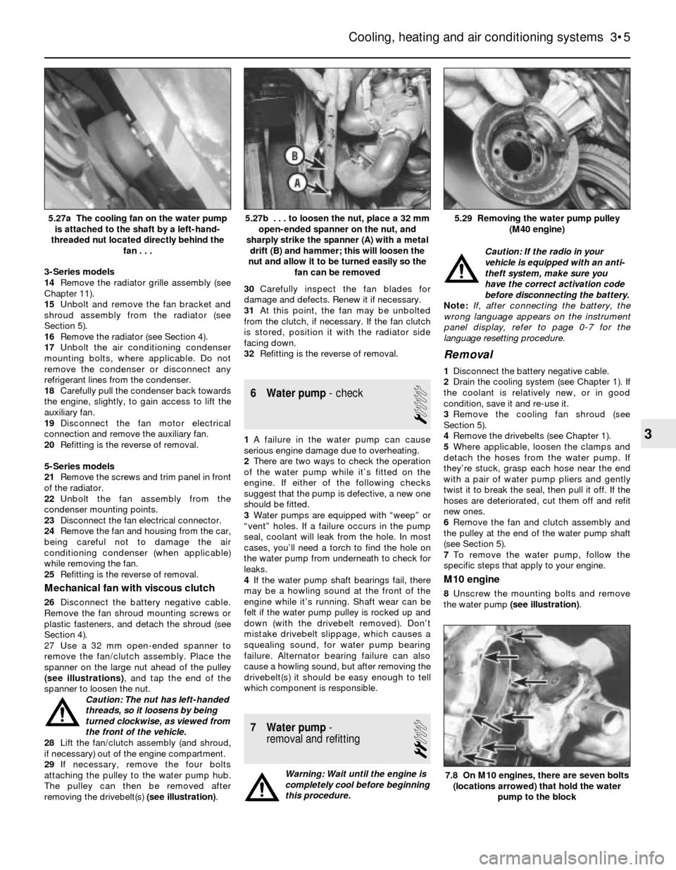
27 Use a 32 mm open-ended spanner to
remove the fan/clutch assembly. Place the
spanner on the large nut ahead of the pulley
(see illustrations), and tap the end of the
spanner to loosen the nut.
Caution: The nut has left-handed
threads, so it loosens by being
turned clockwise, as viewed from
the front of the vehicle.
28Lift the fan/clutch assembly (and shroud,
if necessary) out of the engine compartment.
29If necessary, remove the four bolts
attaching the pulley to the water pump hub.
The pulley can then be removed after
removing the drivebelt(s) (see illustration).30Carefully inspect the fan blades for
damage and defects. Renew it if necessary.
31At this point, the fan may be unbolted
from the clutch, if necessary. If the fan clutch
is stored, position it with the radiator side
facing down.
32Refitting is the reverse of removal.
6 Water pump- check
1
1A failure in the water pump can cause
serious engine damage due to overheating.
2There are two ways to check the operation
of the water pump while it’s fitted on the
engine. If either of the following checks
suggest that the pump is defective, a new one
should be fitted.
3Water pumps are equipped with “weep” or
“vent” holes. If a failure occurs in the pump
seal, coolant will leak from the hole. In most
cases, you’ll need a torch to find the hole on
the water pump from underneath to check for
leaks.
4If the water pump shaft bearings fail, there
may be a howling sound at the front of the
engine while it’s running. Shaft wear can be
felt if the water pump pulley is rocked up and
down (with the drivebelt removed). Don’t
mistake drivebelt slippage, which causes a
squealing sound, for water pump bearing
failure. Alternator bearing failure can also
cause a howling sound, but after removing the
drivebelt(s) it should be easy enough to tell
which component is responsible.
7 Water pump-
removal and refitting
2
Warning: Wait until the engine is
completely cool before beginning
this procedure.Caution: If the radio in your
vehicle is equipped with an anti-
theft system, make sure you
have the correct activation code
before disconnecting the battery.
Note: If, after connecting the battery, the
wrong language appears on the instrument
panel display, refer to page 0-7 for the
language resetting procedure.
Removal
1Disconnect the battery negative cable.
2Drain the cooling system (see Chapter 1). If
the coolant is relatively new, or in good
condition, save it and re-use it.
3Remove the cooling fan shroud (see
Section 5).
4Remove the drivebelts (see Chapter 1).
5Where applicable, loosen the clamps and
detach the hoses from the water pump. If
they’re stuck, grasp each hose near the end
with a pair of water pump pliers and gently
twist it to break the seal, then pull it off. If the
hoses are deteriorated, cut them off and refit
new ones.
6Remove the fan and clutch assembly and
the pulley at the end of the water pump shaft
(see Section 5).
7To remove the water pump, follow the
specific steps that apply to your engine.
M10 engine
8Unscrew the mounting bolts and remove
the water pump (see illustration).
Cooling, heating and air conditioning systems 3•5
5.29 Removing the water pump pulley
(M40 engine)5.27b . . . to loosen the nut, place a 32 mm
open-ended spanner on the nut, and
sharply strike the spanner (A) with a metal
drift (B) and hammer; this will loosen the
nut and allow it to be turned easily so the
fan can be removed5.27a The cooling fan on the water pump
is attached to the shaft by a left-hand-
threaded nut located directly behind the
fan . . .
7.8 On M10 engines, there are seven bolts
(locations arrowed) that hold the water
pump to the block
3
Page 113 of 228
5 Ignition system- general
information and precautions
The ignition system includes the ignition
switch, the battery, the distributor, the primary
(low-voltage/low-tension or LT) and
secondary (high-voltage/high-tension or HT)
wiring circuits, the spark plugs and the spark
plug leads. Models fitted with a carburettor or
L-Jetronic fuel injection are equipped with a
Transistorised Coil Ignition (TCI) system.
Models fitted with the Motronic fuel injection
system have the ignition system incorporated
within the Motronic system (Digital Motor
Electronics or DME).
Transistorised Coil Ignition (TCI)
system
This system is has four major components;
the impulse generator, the ignition control
unit, the coil, and the spark plugs. The
impulse generator provides a timing signal for
the ignition system. Equivalent to cam-
actuated breaker points in a standard
distributor, the impulse generator creates an
A/C voltage signal every time the trigger
wheel tabs pass the impulse generator tabs.
When the ignition control unit (capacitive
discharge unit) receives the voltage signal, it
triggers a spark discharge from the coil by
interrupting the primary coil circuit. The
ignition dwell (coil charging time) is adjusted
by the ignition control unit for the most
intense spark. Note: The air gap (distance
between the impulse generator and trigger
wheel tabs) can be adjusted (see Section 11).
Ignition timing is mechanically adjusted
(see Section 7). A centrifugal advance unit
that consists of spring-loaded rotating
weights advances ignition timing as engine
speed increases. The vacuum advance
adjusts ignition timing to compensate for
changes in engine load.
Motronic ignition system
This system, also known as Digital Motor
Electronics (DME), incorporates all ignition
and fuel injection functions into one central
control unit or ECU (computer). The ignition
timing is based on inputs the ECU receives for
engine load, engine speed, coolant
temperature and intake air temperature. The
only function the distributor performs is the
distribution of the high voltage signal to the
individual spark plugs. The distributor is
attached directly to the cylinder head. There is
no mechanical spark advance system used on
these systems.
Ignition timing is electronically-controlled,
and is not adjustable on Motronic systems.
During starting, a crankshaft position sensor
(reference sensor) relays the crankshaft
position to the ECU, and an initial baseline
ignition point is determined. Once the engineis running, the ignition timing is continually
changing, based on the various input signals
to the ECU. Engine speed is signalled by a
speed sensor. Early Motronic systems have
the position reference sensor and the speed
sensor mounted on the bellhousing over the
flywheel on the left-hand side. Later Motronic
systems have a single sensor (pulse sensor)
mounted over the crankshaft pulley. This
sensor functions as a speed sensor as well as
a position reference sensor. Refer to Sec-
tion 12 for checking and renewing the ignition
sensors. Note: Some models are equipped
with a TDC sensor mounted on the front of the
engine. This sensor is strictly for the BMW
service test unit, and it is not part of the
Motronic ignition system.
Precautions
Certain precautions must be observed
when working on a transistorised ignition
system.
a) Do not disconnect the battery cables
when the engine is running
b) Make sure the ignition control unit (TCI
ignition system) is always well earthed
(see Section 10).
c) Keep water away from the distributor and
HT leads.
d) If a tachometer is to be connected to the
engine, always connect the tachometer
positive (+) lead to the ignition coil
negative terminal (-) and never to the
distributor.
e) Do not allow the coil terminals to be
earthed, as the impulse generator or coil
could be damaged.
f) Do not leave the ignition switch on for
more than ten minutes with the engine
off, or if the engine will not start.
6 Ignition system- check
2
Warning: Because of the high
voltage generated by the ignition
system, extreme care should be
taken whenever an operation is
performed involving ignition components.
This not only includes the impulse
generator (electronic ignition), coil,
distributor and spark plug HT leads, but
related components such as spark plug
connectors, tachometer and other test
equipment.
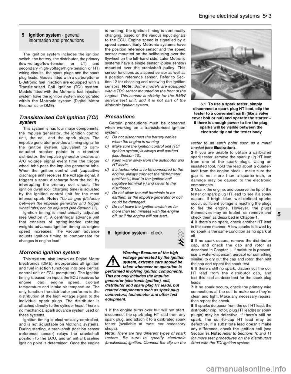
1If the engine turns over but will not start,
disconnect the spark plug HT lead from any
spark plug, and attach it to a calibrated spark
tester (available at most car accessory
shops).
Note:There are two different types of spark
testers. Be sure to specify electronic
(breakerless) ignition. Connect the clip on thetester to an earth point such as a metal
bracket (see illustration).
2If you are unable to obtain a calibrated
spark tester, remove the spark plug HT lead
from one of the spark plugs. Using an
insulated tool, hold the lead about a quarter-
inch from the engine block - make sure the
gap is not more than a quarter-inch, or
damage may be caused to the electronic
components.
3Crank the engine, and observe the tip of the
tester or spark plug HT lead to see if a spark
occurs. If bright-blue, well-defined sparks
occur, sufficient voltage is reaching the plugs
to fire the engine. However, the plugs
themselves may be fouled, so remove and
check them as described in Chapter 1.
4If there’s no spark, check another HT lead
in the same manner. A few sparks followed by
no spark is the same condition as no spark at
all.
5If no spark occurs, remove the distributor
cap, and check the cap and rotor as
described in Chapter 1. If moisture is present,
use a water-dispersant aerosol (or something
similar) to dry out the cap and rotor, then refit
the cap and repeat the spark test.
6If there’s still no spark, disconnect the coil
HT lead from the distributor cap, and
test this lead as described for the spark plug
leads.
7If no spark occurs, check the primary wire
connections at the coil to make sure they’re
clean and tight. Make any necessary repairs,
then repeat the check.
8If sparks do occur from the coil HT lead, the
distributor cap, rotor, plug HT lead(s) or spark
plug(s) may be defective. If there’s still no
spark, the coil-to-cap HT lead may be
defective. If a substitute lead doesn’t make
any difference, check the ignition coil (see
Section 9). Note:Refer to Sections 10 and 11
for more test procedures on the distributors
fitted with the TCI ignition system.
Engine electrical systems 5•3
6.1 To use a spark tester, simply
disconnect a spark plug HT lead, clip the
tester to a convenient earth (like a valve
cover bolt or nut) and operate the starter –
if there is enough power to fire the plug,
sparks will be visible between the
electrode tip and the tester body
5
Page 118 of 228
and down - you should feel a slight drag on
the feeler gauge as it is moved if the gap is
correct. The gap must be as given in this
Chapter’s Specifications.
3To adjust the gap, it is necessary to remove
the impulse generator and the baseplate
assembly from the distributor (see illus-
tration 10.1).
4Follow paragraphs 17 to 24 in Section 10
and loosen the screws that retain the impulse
generator to the baseplate assembly.
5Carefully insert the feeler gauge and tighten
the screws.
6Refit the assembly back into the distributor
and recheck the adjustment.12 Ignition sensors (Motronic
system)- check and renewal
2
Note:Some models are equipped with a TDC
sensor mounted on the front of the engine.
This sensor is strictly for the BMW service test
unit, and is not part of the Motronic ignition
system.
Speed and position sensors
Check
1Locate the two electrical connectors for the
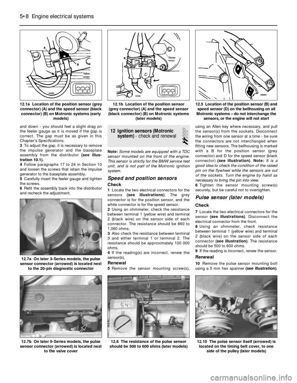
sensors (see illustrations). The grey
connector is for the position sensor, and the
white connector is for the speed sensor.
2Using an ohmmeter, check the resistance
between terminal 1 (yellow wire) and terminal
2 (black wire) on the sensor side of each
connector. The resistance should be 860 to
1,060 ohms.
3Also check the resistance between terminal
3 and either terminal 1 or terminal 2. The
resistance should be approximately 100 000
ohms.
4If the reading(s) are incorrect, renew the
sensor(s).
Renewal
5Remove the sensor mounting screw(s),using an Allen key where necessary, and pull
the sensor(s) from the sockets. Disconnect
the wiring from one sensor at a time - be sure
the connectors are not interchanged when
fitting new sensors. The bellhousing is marked
with a B for the position sensor (grey
connector) and D for the speed sensor (black
connector) (see illustration). Note: It is a
good idea to check the condition of the raised
pin on the flywheel while the sensors are out
of the sockets. Turn the engine by hand as
necessary to bring the pin into view.
6Tighten the sensor mounting screw(s)
securely, but be careful not to overtighten.
Pulse sensor (later models)
Check
7Locate the two electrical connectors for the
sensor (see illustrations). Disconnect the
electrical connector from the front.
8Using an ohmmeter, check resistance
between terminal 1 (yellow wire) and terminal
2 (black wire) on the sensor side of each
connector (see illustration). The resistance
should be 500 to 600 ohms.
9If the reading is incorrect, renew the sensor.
Renewal
10Remove the pulse sensor mounting bolt
using a 5 mm hex spanner (see illustration).
5•8 Engine electrical systems
12.10 The pulse sensor itself (arrowed) is
located on the timing belt cover, to one
side of the pulley (later models)12.8 The resistance of the pulse sensor
should be 500 to 600 ohms (later models)12.7b On later 5-Series models, the pulse
sensor connector (arrowed) is located next
to the valve cover
12.7a On later 3-Series models, the pulse
sensor connector (arrowed) is located next
to the 20-pin diagnostic connector
12.5 Location of the position sensor (B) and
speed sensor (D) on the bellhousing on all
Motronic systems – do not interchange the
sensors, or the engine will not start12.1b Location of the position sensor
(grey connector) (A) and the speed sensor
(black connector) (B) on Motronic systems
(later models)12.1a Location of the position sensor (grey
connector) (A) and the speed sensor (black
connector) (B) on Motronic systems (early
models)
Page 119 of 228
Withdraw the sensor from its bracket and
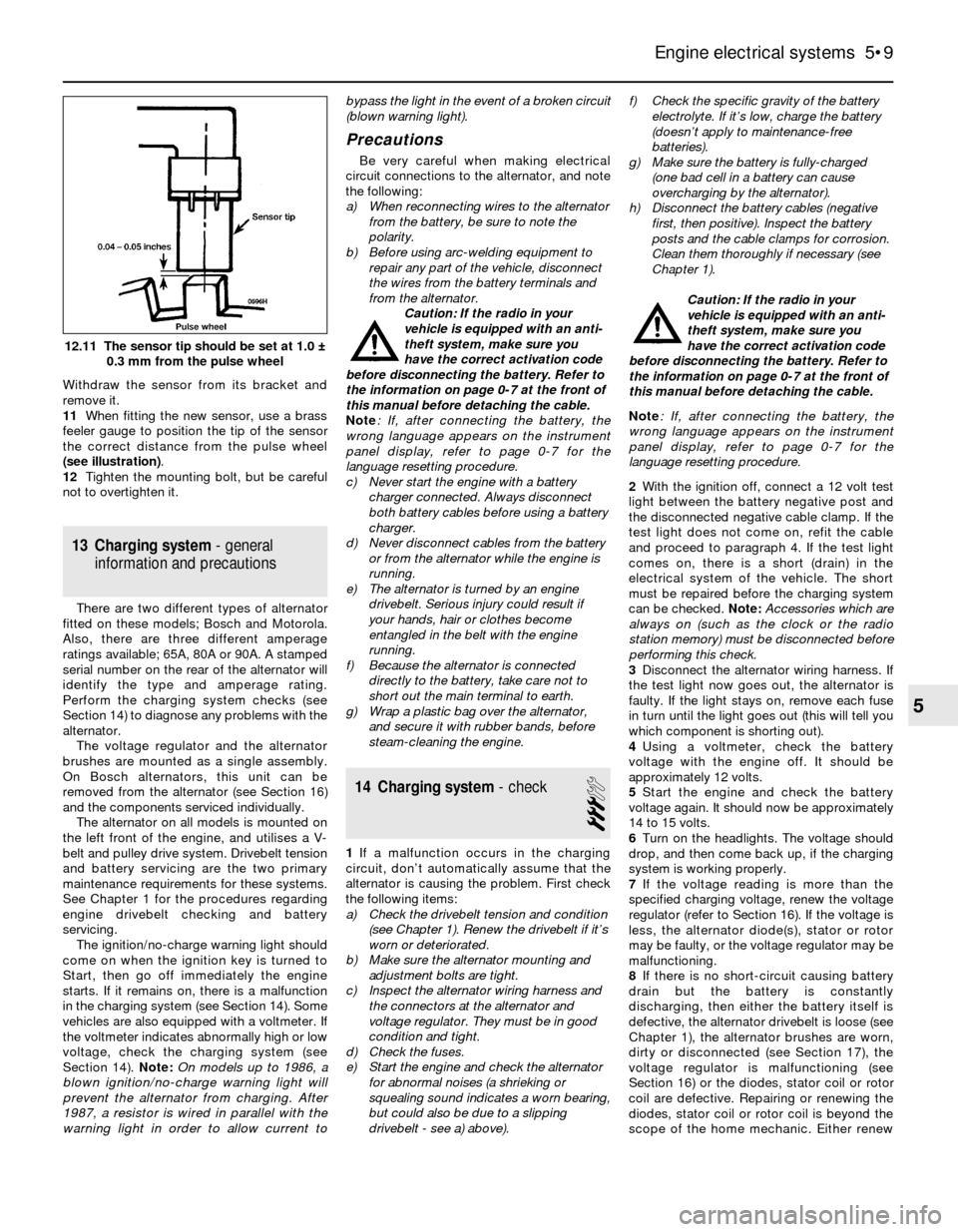
remove it.
11When fitting the new sensor, use a brass
feeler gauge to position the tip of the sensor
the correct distance from the pulse wheel
(see illustration).
12Tighten the mounting bolt, but be careful
not to overtighten it.
13 Charging system- general
information and precautions
There are two different types of alternator
fitted on these models; Bosch and Motorola.
Also, there are three different amperage
ratings available; 65A, 80A or 90A. A stamped
serial number on the rear of the alternator will
identify the type and amperage rating.
Perform the charging system checks (see
Section 14) to diagnose any problems with the
alternator.
The voltage regulator and the alternator
brushes are mounted as a single assembly.
On Bosch alternators, this unit can be
removed from the alternator (see Section 16)
and the components serviced individually.
The alternator on all models is mounted on
the left front of the engine, and utilises a V-
belt and pulley drive system. Drivebelt tension
and battery servicing are the two primary
maintenance requirements for these systems.
See Chapter 1 for the procedures regarding
engine drivebelt checking and battery
servicing.
The ignition/no-charge warning light should
come on when the ignition key is turned to
Start, then go off immediately the engine
starts. If it remains on, there is a malfunction
in the charging system (see Section 14). Some
vehicles are also equipped with a voltmeter. If
the voltmeter indicates abnormally high or low
voltage, check the charging system (see
Section 14). Note:On models up to 1986, a
blown ignition/no-charge warning light will
prevent the alternator from charging. After
1987, a resistor is wired in parallel with the
warning light in order to allow current tobypass the light in the event of a broken circuit
(blown warning light).
Precautions
Be very careful when making electrical
circuit connections to the alternator, and note
the following:
a) When reconnecting wires to the alternator
from the battery, be sure to note the
polarity.
b) Before using arc-welding equipment to
repair any part of the vehicle, disconnect
the wires from the battery terminals and
from the alternator.
Caution: If the radio in your
vehicle is equipped with an anti-
theft system, make sure you
have the correct activation code
before disconnecting the battery. Refer to
the information on page 0-7 at the front of
this manual before detaching the cable.
Note: If, after connecting the battery, the
wrong language appears on the instrument
panel display, refer to page 0-7 for the
language resetting procedure.
c) Never start the engine with a battery
charger connected. Always disconnect
both battery cables before using a battery
charger.
d) Never disconnect cables from the battery
or from the alternator while the engine is
running.
e) The alternator is turned by an engine
drivebelt. Serious injury could result if
your hands, hair or clothes become
entangled in the belt with the engine
running.
f) Because the alternator is connected
directly to the battery, take care not to
short out the main terminal to earth.
g) Wrap a plastic bag over the alternator,
and secure it with rubber bands, before
steam-cleaning the engine.
14 Charging system- check
3
1If a malfunction occurs in the charging
circuit, don’t automatically assume that the
alternator is causing the problem. First check
the following items:
a) Check the drivebelt tension and condition
(see Chapter 1). Renew the drivebelt if it’s
worn or deteriorated.
b) Make sure the alternator mounting and
adjustment bolts are tight.
c) Inspect the alternator wiring harness and
the connectors at the alternator and
voltage regulator. They must be in good
condition and tight.
d) Check the fuses.
e) Start the engine and check the alternator
for abnormal noises (a shrieking or
squealing sound indicates a worn bearing,
but could also be due to a slipping
drivebelt - see a) above).f) Check the specific gravity of the battery
electrolyte. If it’s low, charge the battery
(doesn’t apply to maintenance-free
batteries).
g) Make sure the battery is fully-charged
(one bad cell in a battery can cause
overcharging by the alternator).
h) Disconnect the battery cables (negative
first, then positive). Inspect the battery
posts and the cable clamps for corrosion.
Clean them thoroughly if necessary (see
Chapter 1).
Caution: If the radio in your
vehicle is equipped with an anti-
theft system, make sure you
have the correct activation code
before disconnecting the battery. Refer to
the information on page 0-7 at the front of
this manual before detaching the cable.
Note: If, after connecting the battery, the
wrong language appears on the instrument
panel display, refer to page 0-7 for the
language resetting procedure.
2With the ignition off, connect a 12 volt test
light between the battery negative post and
the disconnected negative cable clamp. If the
test light does not come on, refit the cable
and proceed to paragraph 4. If the test light
comes on, there is a short (drain) in the
electrical system of the vehicle. The short
must be repaired before the charging system
can be checked. Note: Accessories which are
always on (such as the clock or the radio
station memory) must be disconnected before
performing this check.
3Disconnect the alternator wiring harness. If
the test light now goes out, the alternator is
faulty. If the light stays on, remove each fuse
in turn until the light goes out (this will tell you
which component is shorting out).
4Using a voltmeter, check the battery
voltage with the engine off. It should be
approximately 12 volts.
5Start the engine and check the battery
voltage again. It should now be approximately
14 to 15 volts.
6Turn on the headlights. The voltage should
drop, and then come back up, if the charging
system is working properly.
7If the voltage reading is more than the
specified charging voltage, renew the voltage
regulator (refer to Section 16). If the voltage is
less, the alternator diode(s), stator or rotor
may be faulty, or the voltage regulator may be
malfunctioning.
8If there is no short-circuit causing battery
drain but the battery is constantly
discharging, then either the battery itself is
defective, the alternator drivebelt is loose (see
Chapter 1), the alternator brushes are worn,
dirty or disconnected (see Section 17), the
voltage regulator is malfunctioning (see
Section 16) or the diodes, stator coil or rotor
coil are defective. Repairing or renewing the
diodes, stator coil or rotor coil is beyond the
scope of the home mechanic. Either renew
Engine electrical systems 5•9
12.11 The sensor tip should be set at 1.0 ±
0.3 mm from the pulse wheel
5
Page 120 of 228
the alternator complete, or take it to an
automotive electrician, who may be able to
overhaul it. Note:On models up to 1986, a
blown ignition/no-charge warning light bulb
will prevent the alternator from charging. After
1987, a resistor is wired in parallel with the
warning light, in order to allow current to
bypass the light in the event of a broken circuit
(blown warning light).
15 Alternator-
removal and refitting
1
Caution: If the radio in your
vehicle is equipped with an anti-
theft system, make sure you
have the correct activation code
before disconnecting the battery. Refer to
the information on page 0-7 at the front of
this manual before detaching the cable.
Note: If, after connecting the battery, the
wrong language appears on the instrument
panel display, refer to page 0-7 for the
language resetting procedure.
Removal
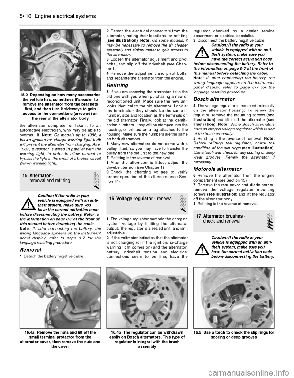
1Detach the battery negative cable.2Detach the electrical connectors from the
alternator, noting their locations for refitting
(see illustration). Note: On some models, it
may be necessary to remove the air cleaner
assembly and airflow meter to gain access to
the alternator.
3Loosen the alternator adjustment and pivot
bolts, and slip off the drivebelt (see Chap-
ter 1).
4Remove the adjustment and pivot bolts,
and separate the alternator from the engine.
Refitting
5If you are renewing the alternator, take the
old one with you when purchasing a new or
reconditioned unit. Make sure the new unit
looks identical to the old alternator. Look at
the terminals - they should be the same in
number, size and location as the terminals on
the old alternator. Finally, look at the identifi-
cation numbers - they will be stamped into the
housing, or printed on a tag attached to the
housing. Make sure the numbers are the same
on both alternators.
6Many new alternators do not come with a
pulley fitted, so you may have to transfer the
pulley from the old unit to the new one.
7Refitting is the reverse of removal.
8After the alternator is fitted, adjust the
drivebelt tension (see Chapter 1).
9Check the charging voltage to verify
proper operation of the alternator (see Sec-
tion 14).
16 Voltage regulator- renewal
1
1The voltage regulator controls the charging
system voltage by limiting the alternator
output. The regulator is a sealed unit, and isn’t
adjustable.
2If the voltmeter indicates that the alternator
is not charging (or if the ignition/no-charge
warning light comes on) and the alternator,
battery, drivebelt tension and electrical
connections seem to be fine, have theregulator checked by a dealer service
department or electrical specialist.
3Disconnect the battery negative cable.
Caution: If the radio in your
vehicle is equipped with an anti-
theft system, make sure you
have the correct activation code
before disconnecting the battery. Refer to
the information on page 0-7 at the front of
this manual before detaching the cable.
Note: If, after connecting the battery, the
wrong language appears on the instrument
panel display, refer to page 0-7 for the
language resetting procedure.
Bosch alternator
4The voltage regulator is mounted externally
on the alternator housing. To renew the
regulator, remove the mounting screws (see
illustration)and lift it off the alternator (see
illustration). Note: Some Bosch alternators
have an integral voltage regulator which is part
of the brush assembly.
5Refitting is the reverse of removal. Note:
Before refitting the regulator, check the
condition of the slip rings(see illustration).
Use a torch and check for any scoring or deep
wear grooves. Renew the alternator if
necessary.
Motorola alternator
6Remove the alternator from the engine
compartment (see Section 15).
7Remove the rear cover and diode carrier,
remove the voltage regulator mounting
screws (see illustration)and lift the regulator
off the alternator body.
8Refitting is the reverse of removal.
17 Alternator brushes-
check and renewal
3
Caution: If the radio in your
vehicle is equipped with an anti-
theft system, make sure you
have the correct activation code
before disconnecting the battery.
5•10 Engine electrical systems
16.5 Use a torch to check the slip rings for
scoring or deep grooves16.4b The regulator can be withdrawn
easily on Bosch alternators. This type of
regulator is integral with the brush
assembly16.4a Remove the nuts and lift off the
small terminal protector from the
alternator cover, then remove the nuts and
the cover
15.2 Depending on how many accessories
the vehicle has, sometimes it’s easier to
remove the alternator from the brackets
first, and then turn it sideways to gain
access to the connections (arrowed) on
the rear of the alternator body
Page 126 of 228
slightly by hand. Release the throttle slowly
until it reaches 0.2 to 0.6 mm from the throttle
stop. There should be continuity.
29Check the resistance between terminals 3
and 18 as the throttle is opened. There should
be continuity when the throttle switch is within
8 to 12 degrees of fully-open. If the readings
are incorrect, adjust the TPS.
30If all the resistance readings are correct
and the TPS is properly adjusted, check for
power (5 volts) at the sensor, and if necessary
trace any wiring circuit problems between the
sensor and ECU (see Chapter 12).
Adjustment
31If the adjustment is not as specified
(paragraphs 28 to 30), loosen the screws on
the TPS, and rotate the sensor into the correct
adjustment. Follow the procedure for
checking the TPS given above, and tighten
the screws when the setting is correct.
32Recheck the TPS once more; if the
readings are correct, reconnect the TPS
harness connector.
Early 535i models with automatic
transmission
Check
33First test the continuity of the TPS. Follow
paragraphs 28 to 30 and check for continuity.
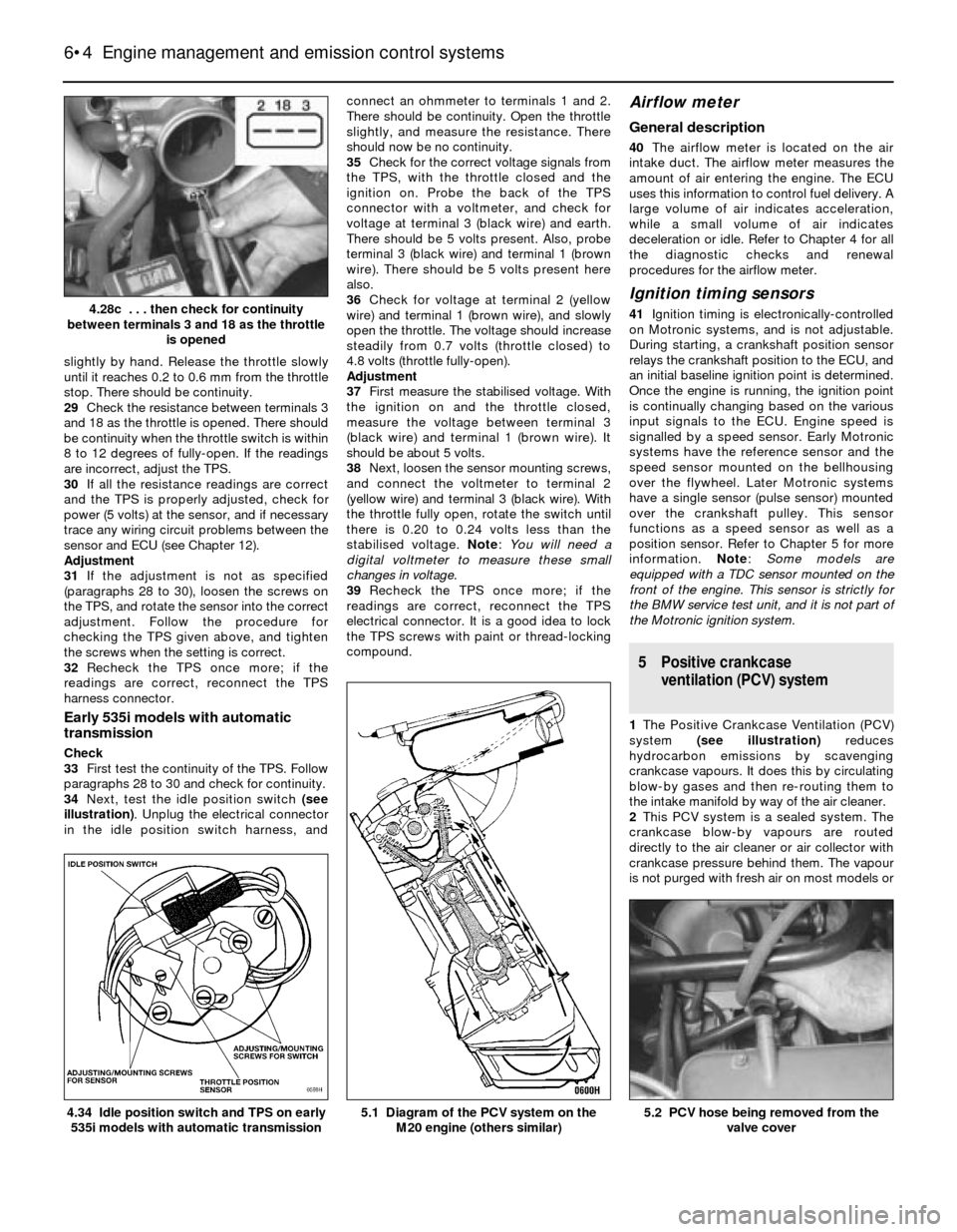
34Next, test the idle position switch (see
illustration). Unplug the electrical connector
in the idle position switch harness, andconnect an ohmmeter to terminals 1 and 2.
There should be continuity. Open the throttle
slightly, and measure the resistance. There
should now be no continuity.
35Check for the correct voltage signals from
the TPS, with the throttle closed and the
ignition on. Probe the back of the TPS
connector with a voltmeter, and check for
voltage at terminal 3 (black wire) and earth.
There should be 5 volts present. Also, probe
terminal 3 (black wire) and terminal 1 (brown
wire). There should be 5 volts present here
also.
36Check for voltage at terminal 2 (yellow
wire) and terminal 1 (brown wire), and slowly
open the throttle. The voltage should increase
steadily from 0.7 volts (throttle closed) to
4.8 volts (throttle fully-open).
Adjustment
37First measure the stabilised voltage. With
the ignition on and the throttle closed,
measure the voltage between terminal 3
(black wire) and terminal 1 (brown wire). It
should be about 5 volts.
38Next, loosen the sensor mounting screws,
and connect the voltmeter to terminal 2
(yellow wire) and terminal 3 (black wire). With
the throttle fully open, rotate the switch until
there is 0.20 to 0.24 volts less than the
stabilised voltage. Note: You will need a
digital voltmeter to measure these small
changes in voltage.
39Recheck the TPS once more; if the
readings are correct, reconnect the TPS
electrical connector. It is a good idea to lock
the TPS screws with paint or thread-locking
compound.
Airflow meter
General description
40The airflow meter is located on the air
intake duct. The airflow meter measures the
amount of air entering the engine. The ECU
uses this information to control fuel delivery. A
large volume of air indicates acceleration,
while a small volume of air indicates
deceleration or idle. Refer to Chapter 4 for all
the diagnostic checks and renewal
procedures for the airflow meter.
Ignition timing sensors
41Ignition timing is electronically-controlled
on Motronic systems, and is not adjustable.
During starting, a crankshaft position sensor
relays the crankshaft position to the ECU, and
an initial baseline ignition point is determined.
Once the engine is running, the ignition point
is continually changing based on the various
input signals to the ECU. Engine speed is
signalled by a speed sensor. Early Motronic
systems have the reference sensor and the
speed sensor mounted on the bellhousing
over the flywheel. Later Motronic systems
have a single sensor (pulse sensor) mounted
over the crankshaft pulley. This sensor
functions as a speed sensor as well as a
position sensor. Refer to Chapter 5 for more
information. Note: Some models are
equipped with a TDC sensor mounted on the
front of the engine. This sensor is strictly for
the BMW service test unit, and it is not part of
the Motronic ignition system.
5 Positive crankcase
ventilation (PCV) system
1The Positive Crankcase Ventilation (PCV)
system (see illustration)reduces
hydrocarbon emissions by scavenging
crankcase vapours. It does this by circulating
blow-by gases and then re-routing them to
the intake manifold by way of the air cleaner.
2This PCV system is a sealed system. The
crankcase blow-by vapours are routed
directly to the air cleaner or air collector with
crankcase pressure behind them. The vapour
is not purged with fresh air on most models or
6•4 Engine management and emission control systems
5.2 PCV hose being removed from the
valve cover5.1 Diagram of the PCV system on the
M20 engine (others similar)4.34 Idle position switch and TPS on early
535i models with automatic transmission
4.28c . . . then check for continuity
between terminals 3 and 18 as the throttle
is opened
Page 157 of 228
21 Steering box (5-Series)-
removal and refitting
4
Removal
Note:If you find that the steering box is
defective, it is not recommended that you
overhaul it. Because of the special tools
needed to do the job, it is best to let your
dealer service department overhaul it for you
(otherwise, fit a new unit). Removal and
refitting the steering box is outlined here.
1On 5-Series E28 (“old-shape”) models,
discharge the hydraulic system by depressing
the brake pedal about 20 times.
2Using a large syringe or hand pump, empty
the power steering fluid reservoir (see Chap-
ter 1).
3Raise the front of the vehicle and support it
securely on axle stands.
4Support the front of the engine with a trolley
jack. Place a block of wood between the jack
head and the sump to protect the sump from
damage.
5Remove the pivot bolts from the inner ends
of the front control arms (see Section 4).
6Remove the nuts from the left and right
engine mountings (see Chapter 2).
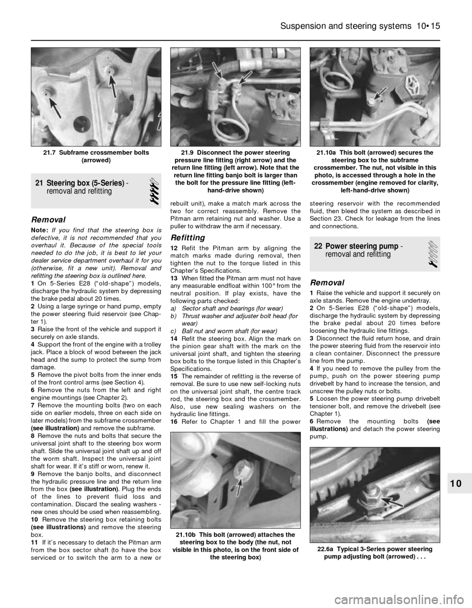
7Remove the mounting bolts (two on each
side on earlier models, three on each side on
later models) from the subframe crossmember
(see illustration)and remove the subframe.
8Remove the nuts and bolts that secure the
universal joint shaft to the steering box worm
shaft. Slide the universal joint shaft up and off
the worm shaft. Inspect the universal joint
shaft for wear. If it’s stiff or worn, renew it.
9Remove the banjo bolts, and disconnect
the hydraulic pressure line and the return line
from the box (see illustration). Plug the ends
of the lines to prevent fluid loss and
contamination. Discard the sealing washers -
new ones should be used when reassembling.
10Remove the steering box retaining bolts
(see illustrations)and remove the steering
box.
11If it’s necessary to detach the Pitman arm
from the box sector shaft (to have the box
serviced or to switch the arm to a new orrebuilt unit), make a match mark across the
two for correct reassembly. Remove the
Pitman arm retaining nut and washer. Use a
puller to withdraw the arm if necessary.
Refitting
12Refit the Pitman arm by aligning the
match marks made during removal, then
tighten the nut to the torque listed in this
Chapter’s Specifications.
13When fitted the Pitman arm must not have
any measurable endfloat within 100° from the
neutral position. If play exists, have the
following parts checked:
a) Sector shaft and bearings (for wear)
b) Thrust washer and adjuster bolt head (for
wear)
c) Ball nut and worm shaft (for wear)
14Refit the steering box. Align the mark on
the pinion gear shaft with the mark on the
universal joint shaft, and tighten the steering
box bolts to the torque listed in this Chapter’s
Specifications.
15The remainder of refitting is the reverse of
removal. Be sure to use new self-locking nuts
on the universal joint shaft, the centre track
rod, the steering box and the crossmember.
Also, use new sealing washers on the
hydraulic line fittings.
16Refer to Chapter 1 and fill the powersteering reservoir with the recommended
fluid, then bleed the system as described in
Section 23. Check for leakage from the lines
and connections.22 Power steering pump-
removal and refitting
1
Removal
1Raise the vehicle and support it securely on
axle stands. Remove the engine undertray.
2On 5-Series E28 (“old-shape”) models,
discharge the hydraulic system by depressing
the brake pedal about 20 times before
loosening the hydraulic line fittings.
3Disconnect the fluid return hose, and drain
the power steering fluid from the reservoir into
a clean container. Disconnect the pressure
line from the pump.
4If you need to remove the pulley from the
pump, push on the power steering pump
drivebelt by hand to increase the tension, and
unscrew the pulley nuts or bolts.
5Loosen the power steering pump drivebelt
tensioner bolt, and remove the drivebelt (see
Chapter 1).
6Remove the mounting bolts (see
illustrations)and detach the power steering
pump.
Suspension and steering systems 10•15
21.10a This bolt (arrowed) secures the
steering box to the subframe
crossmember. The nut, not visible in this
photo, is accessed through a hole in the
crossmember (engine removed for clarity,
left-hand-drive shown)21.9 Disconnect the power steering
pressure line fitting (right arrow) and the
return line fitting (left arrow). Note that the
return line fitting banjo bolt is larger than
the bolt for the pressure line fitting (left-
hand-drive shown)21.7 Subframe crossmember bolts
(arrowed)
22.6a Typical 3-Series power steering
pump adjusting bolt (arrowed) . . .
21.10b This bolt (arrowed) attaches the
steering box to the body (the nut, not
visible in this photo, is on the front side of
the steering box)
10
Page 221 of 228
REF•21
REF
Glossary of Technical Terms
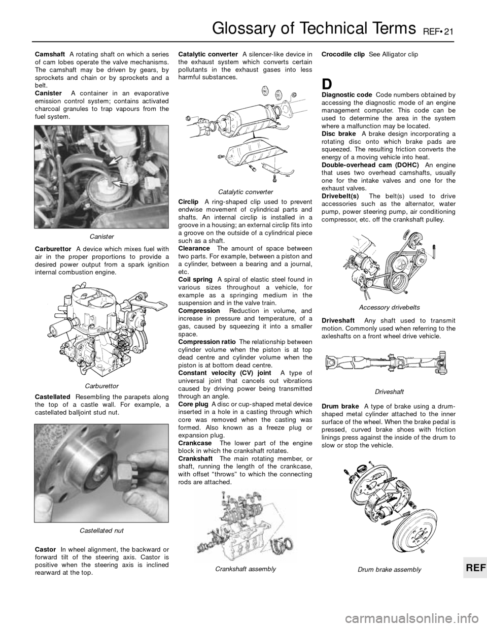
CamshaftA rotating shaft on which a series
of cam lobes operate the valve mechanisms.
The camshaft may be driven by gears, by
sprockets and chain or by sprockets and a
belt.
CanisterA container in an evaporative
emission control system; contains activated
charcoal granules to trap vapours from the
fuel system.
CarburettorA device which mixes fuel with
air in the proper proportions to provide a
desired power output from a spark ignition
internal combustion engine.
CastellatedResembling the parapets along
the top of a castle wall. For example, a
castellated balljoint stud nut.
CastorIn wheel alignment, the backward or
forward tilt of the steering axis. Castor is
positive when the steering axis is inclined
rearward at the top.Catalytic converterA silencer-like device in
the exhaust system which converts certain
pollutants in the exhaust gases into less
harmful substances.
CirclipA ring-shaped clip used to prevent
endwise movement of cylindrical parts and
shafts. An internal circlip is installed in a
groove in a housing; an external circlip fits into
a groove on the outside of a cylindrical piece
such as a shaft.
ClearanceThe amount of space between
two parts. For example, between a piston and
a cylinder, between a bearing and a journal,
etc.
Coil springA spiral of elastic steel found in
various sizes throughout a vehicle, for
example as a springing medium in the
suspension and in the valve train.
CompressionReduction in volume, and
increase in pressure and temperature, of a
gas, caused by squeezing it into a smaller
space.
Compression ratioThe relationship between
cylinder volume when the piston is at top
dead centre and cylinder volume when the
piston is at bottom dead centre.
Constant velocity (CV) jointA type of
universal joint that cancels out vibrations
caused by driving power being transmitted
through an angle.
Core plugA disc or cup-shaped metal device
inserted in a hole in a casting through which
core was removed when the casting was
formed. Also known as a freeze plug or
expansion plug.
CrankcaseThe lower part of the engine
block in which the crankshaft rotates.
CrankshaftThe main rotating member, or
shaft, running the length of the crankcase,
with offset “throws” to which the connecting
rods are attached.Crocodile clipSee Alligator clip
DDiagnostic codeCode numbers obtained by
accessing the diagnostic mode of an engine
management computer. This code can be
used to determine the area in the system
where a malfunction may be located.
Disc brakeA brake design incorporating a
rotating disc onto which brake pads are
squeezed. The resulting friction converts the
energy of a moving vehicle into heat.
Double-overhead cam (DOHC)An engine
that uses two overhead camshafts, usually
one for the intake valves and one for the
exhaust valves.
Drivebelt(s)The belt(s) used to drive
accessories such as the alternator, water
pump, power steering pump, air conditioning
compressor, etc. off the crankshaft pulley.
DriveshaftAny shaft used to transmit
motion. Commonly used when referring to the
axleshafts on a front wheel drive vehicle.
Drum brakeA type of brake using a drum-
shaped metal cylinder attached to the inner
surface of the wheel. When the brake pedal is
pressed, curved brake shoes with friction
linings press against the inside of the drum to
slow or stop the vehicle.
Castellated nut
Catalytic converter
Crankshaft assembly
Carburettor
Canister
Drum brake assembly
Accessory drivebelts
Driveshaft