ESP BMW 3 SERIES 1984 E30 Owner's Manual
[x] Cancel search | Manufacturer: BMW, Model Year: 1984, Model line: 3 SERIES, Model: BMW 3 SERIES 1984 E30Pages: 228, PDF Size: 7.04 MB
Page 96 of 228
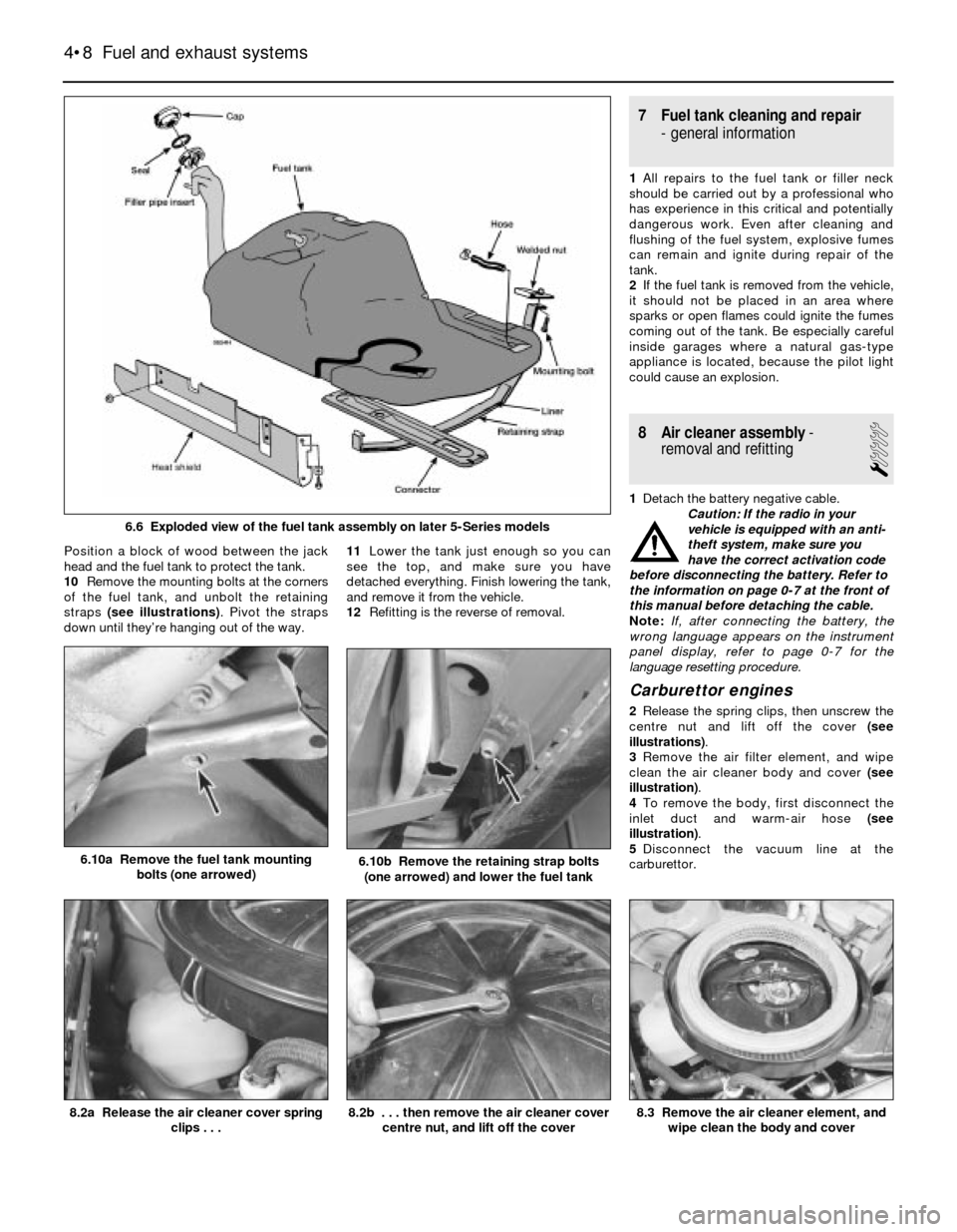
Position a block of wood between the jack
head and the fuel tank to protect the tank.
10Remove the mounting bolts at the corners
of the fuel tank, and unbolt the retaining
straps (see illustrations). Pivot the straps
down until they’re hanging out of the way.11Lower the tank just enough so you can
see the top, and make sure you have
detached everything. Finish lowering the tank,
and remove it from the vehicle.
12Refitting is the reverse of removal.
7 Fuel tank cleaning and repair
- general information
1All repairs to the fuel tank or filler neck
should be carried out by a professional who
has experience in this critical and potentially
dangerous work. Even after cleaning and
flushing of the fuel system, explosive fumes
can remain and ignite during repair of the
tank.
2If the fuel tank is removed from the vehicle,
it should not be placed in an area where
sparks or open flames could ignite the fumes
coming out of the tank. Be especially careful
inside garages where a natural gas-type
appliance is located, because the pilot light
could cause an explosion.
8 Air cleaner assembly-
removal and refitting
1
1Detach the battery negative cable.
Caution: If the radio in your
vehicle is equipped with an anti-
theft system, make sure you
have the correct activation code
before disconnecting the battery. Refer to
the information on page 0-7 at the front of
this manual before detaching the cable.
Note: If, after connecting the battery, the
wrong language appears on the instrument
panel display, refer to page 0-7 for the
language resetting procedure.
Carburettor engines
2Release the spring clips, then unscrew the
centre nut and lift off the cover (see
illustrations).
3Remove the air filter element, and wipe
clean the air cleaner body and cover (see
illustration).
4To remove the body, first disconnect the
inlet duct and warm-air hose (see
illustration).
5Disconnect the vacuum line at the
carburettor.
4•8 Fuel and exhaust systems
8.3 Remove the air cleaner element, and
wipe clean the body and cover8.2b . . . then remove the air cleaner cover
centre nut, and lift off the cover8.2a Release the air cleaner cover spring
clips . . .
6.10a Remove the fuel tank mounting
bolts (one arrowed)6.10b Remove the retaining strap bolts
(one arrowed) and lower the fuel tank
6.6 Exploded view of the fuel tank assembly on later 5-Series models
Page 102 of 228
Throttle positioner (2BE)
24Special tools are required to carry out a
comprehensive adjustment on the 2BE
carburettor. This work should therefore be left
to a BMW dealer.
13 Fuel injection -
general information
The fuel injection system is composed of
three basic sub-systems: fuel system, air
intake system and electronic control system.
Fuel system
An electric fuel pump, located inside the
fuel tank or beside the fuel tank, supplies fuel
under constant pressure to the fuel rail, which
distributes fuel evenly to all injectors. From
the fuel rail, fuel is injected into the intake
ports, just above the intake valves, by the fuel
injectors. The amount of fuel supplied by the
injectors is precisely controlled by an
Electronic Control Unit (ECU). An additional
injector, known as the cold start injector (L-
Jetronic and early Motronic systems only),
supplies extra fuel into the intake manifold for
starting. A pressure regulator controls system
pressure in relation to intake manifold
vacuum. A fuel filter between the fuel pump
and the fuel rail filters the fuel, to protect the
components of the system.
Air intake system
The air intake system consists of an air filter
housing, an airflow meter, a throttle body, the
intake manifold, and the associated ducting.
The airflow meter is an information-gathering
device for the ECU. These models are
equipped with the vane-type airflow meter. A
potentiometer measures intake airflow, and a
temperature sensor measures intake air
temperature. This information helps the ECU
determine the amount of fuel to be injected by
the injectors (injection duration). The throttle
plate inside the throttle body is controlled by
the driver. As the throttle plate opens, the
amount of air that can pass through the
system increases, so the potentiometer opens
further and the ECU signals the injectors to
increase the amount of fuel delivered to the
intake ports.
Electronic control system
The computer control system controls the
fuel system and other systems by means of
an Electronic Control Unit (ECU). The ECU
receives signals from a number of information
sensors which monitor such variables as
intake air volume, intake air temperature,
coolant temperature, engine rpm,
acceleration/deceleration, and exhaust
oxygen content. These signals help the ECU
determine the injection duration necessary for
the optimum air/fuel ratio. These sensors and
their corresponding ECU-controlled outputactuators are located throughout the engine
compartment. For further information
regarding the ECU and its relationship to the
engine electrical systems and ignition system,
refer to Chapters 5 and 6.
Either an L-Jetronic system or a Motronic
system is fitted. Later models have an
updated version of the original Motronic
system.
14 Fuel injection systems
L-Jetronic fuel injection system
The Bosch L-Jetronic fuel injection system
is used on most 3-Series models up to 1987,
and on most E28 (“old-shape”) 5-Series
models. It is an electronically-controlled fuel
injection system that utilises one solenoid-
operated fuel injector per cylinder. The system
is governed by an Electronic Control Unit
(ECU) which processes information sent by
various sensors, and in turn precisely
meters the fuel to the cylinders by
adjusting the amount of time that the injectors
are open.
An electric fuel pump delivers fuel under
high pressure to the injectors, through the fuel
feed line and an in-line filter. A pressure
regulator keeps fuel available at an optimum
pressure, allowing pressure to rise or fall
depending on engine speed and load. Any
excess fuel is returned to the fuel tank by a
separate line.
A sensor in the air intake duct constantly
measures the mass of the incoming air, and
the ECU adjusts the fuel mixture to provide an
optimum air/fuel ratio.
Other components incorporated in the
system are the throttle valve (which controls
airflow to the engine), the coolant temperature
sensor, the throttle position switch, idle
stabiliser valve (which bypasses air around
the throttle plate to control idle speed) and
associated relays and fuses.
Motronic fuel injection system
The Motronic system combines the fuel
control of the L-Jetronic fuel injection system
with the control of ignition timing, idle speed
and emissions into one control unit.
The fuel injection and idle speed control
functions are similar to those used on the L-
Jetronic system described above. For more
information on the Motronic system, see
Chapter 6.
An oxygen sensor is mounted in the
exhaust system on later models with a
catalytic converter. This sensor continually
reads the oxygen content of the exhaust gas.
The information is used by the ECU to adjust
the duration of injection, making it possible to
adjust the fuel mixture for optimum converter
efficiency and minimum emissions.
15 Fuel injection system-
check
2
Warning: Fuel is extremely
flammable, so take extra
precautions when you work on
any part of the fuel system. Don’t
smoke, or allow open flames or bare light
bulbs, near the work area. Don’t work in a
garage where a natural gas-type appliance
(such as a water heater or clothes dryer)
with a pilot light is present. If you spill any
fuel on your skin, rinse it off immediately
with soap and water. When you perform
any kind of work on the fuel system, wear
safety glasses, and have a fire
extinguisher on hand.
1Check the earth wire connections. Check
all wiring harness connectors that are related
to the system. Loose connectors and poor
earths can cause many problems that
resemble more serious malfunctions.
2Make sure the battery is fully charged, as
the control unit and sensors depend on an
accurate supply voltage in order to properly
meter the fuel.
3Check the air filter element - a dirty or
partially-blocked filter will severely impede
performance and economy (see Chapter 1).
4If a blown fuse is found, renew it and see if
it blows again. If it does, search for an earthed
wire in the harness related to the system.
5Check the air intake duct from the airflow
meter to the intake manifold for leaks. Intake
air leaks can cause a variety of problems. Also
check the condition of the vacuum hoses
connected to the intake manifold.
6Remove the air intake duct from the throttle
body, and check for dirt, carbon and other
residue build-up. If it’s dirty, clean it with
carburettor cleaner and a toothbrush.
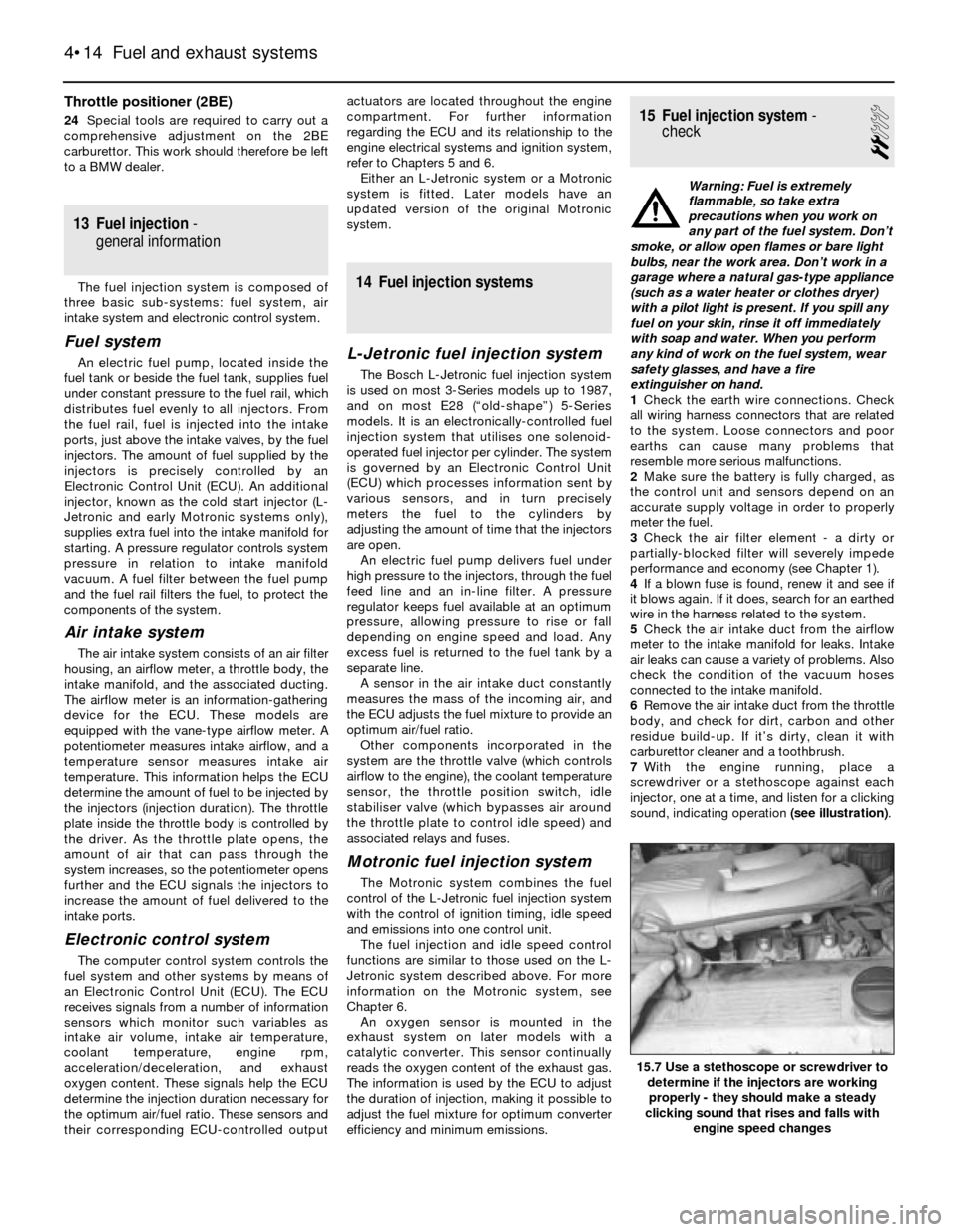
7With the engine running, place a
screwdriver or a stethoscope against each
injector, one at a time, and listen for a clicking
sound, indicating operation (see illustration).
4•14 Fuel and exhaust systems
15.7 Use a stethoscope or screwdriver to
determine if the injectors are working
properly - they should make a steady
clicking sound that rises and falls with
engine speed changes
Page 103 of 228
8Check the fuel system pressure (see
Section 3).
9If these checks do not locate the problem,
take the vehicle to a BMW dealer, who will be
able to read the fault codes stored in the ECU,
using special equipment.
16 Airflow meter- check,
removal and refitting
2
Check (L-Jetronic systems)
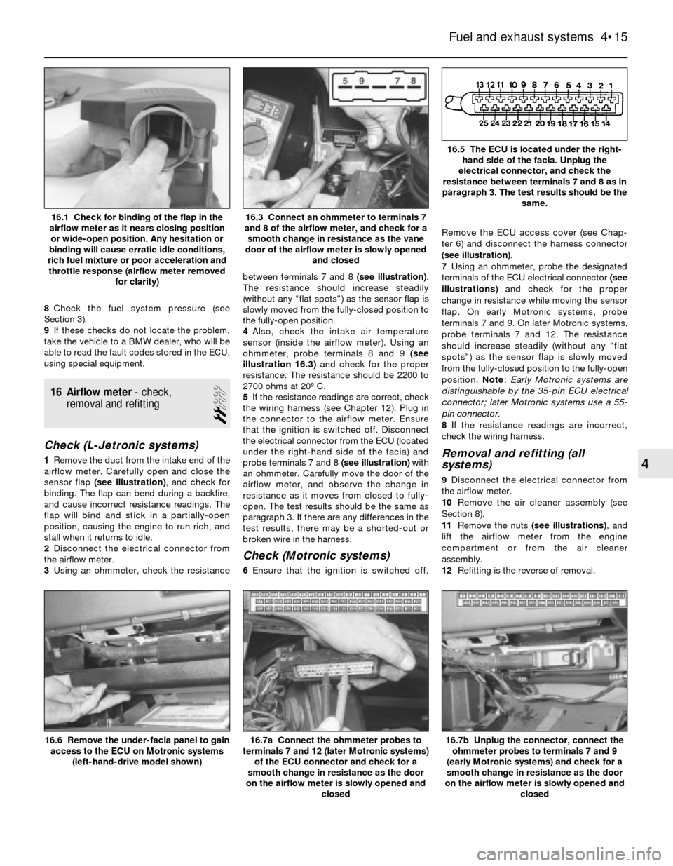
1Remove the duct from the intake end of the
airflow meter. Carefully open and close the
sensor flap (see illustration), and check for
binding. The flap can bend during a backfire,
and cause incorrect resistance readings. The
flap will bind and stick in a partially-open
position, causing the engine to run rich, and
stall when it returns to idle.
2Disconnect the electrical connector from
the airflow meter.
3Using an ohmmeter, check the resistancebetween terminals 7 and 8 (see illustration).
The resistance should increase steadily
(without any “flat spots”) as the sensor flap is
slowly moved from the fully-closed position to
the fully-open position.
4Also, check the intake air temperature
sensor (inside the airflow meter). Using an
ohmmeter, probe terminals 8 and 9 (see
illustration 16.3)and check for the proper
resistance. The resistance should be 2200 to
2700 ohms at 20º C.
5If the resistance readings are correct, check
the wiring harness (see Chapter 12). Plug in
the connector to the airflow meter. Ensure
that the ignition is switched off. Disconnect
the electrical connector from the ECU (located
under the right-hand side of the facia) and
probe terminals 7 and 8 (see illustration)with
an ohmmeter. Carefully move the door of the
airflow meter, and observe the change in
resistance as it moves from closed to fully-
open. The test results should be the same as
paragraph 3. If there are any differences in the
test results, there may be a shorted-out or
broken wire in the harness.
Check (Motronic systems)
6Ensure that the ignition is switched off.Remove the ECU access cover (see Chap-
ter 6) and disconnect the harness connector
(see illustration).
7Using an ohmmeter, probe the designated
terminals of the ECU electrical connector (see
illustrations)and check for the proper
change in resistance while moving the sensor
flap. On early Motronic systems, probe
terminals 7 and 9. On later Motronic systems,
probe terminals 7 and 12. The resistance
should increase steadily (without any “flat
spots”) as the sensor flap is slowly moved
from the fully-closed position to the fully-open
position. Note: Early Motronic systems are
distinguishable by the 35-pin ECU electrical
connector; later Motronic systems use a 55-
pin connector.
8If the resistance readings are incorrect,
check the wiring harness.
Removal and refitting (all
systems)
9Disconnect the electrical connector from
the airflow meter.
10Remove the air cleaner assembly (see
Section 8).
11Remove the nuts (see illustrations), and
lift the airflow meter from the engine
compartment or from the air cleaner
assembly.
12Refitting is the reverse of removal.
Fuel and exhaust systems 4•15
16.5 The ECU is located under the right-
hand side of the facia. Unplug the
electrical connector, and check the
resistance between terminals 7 and 8 as in
paragraph 3. The test results should be the
same.
16.3 Connect an ohmmeter to terminals 7
and 8 of the airflow meter, and check for a
smooth change in resistance as the vane
door of the airflow meter is slowly opened
and closed16.1 Check for binding of the flap in the
airflow meter as it nears closing position
or wide-open position. Any hesitation or
binding will cause erratic idle conditions,
rich fuel mixture or poor acceleration and
throttle response (airflow meter removed
for clarity)
16.7b Unplug the connector, connect the
ohmmeter probes to terminals 7 and 9
(early Motronic systems) and check for a
smooth change in resistance as the door
on the airflow meter is slowly opened and
closed16.7a Connect the ohmmeter probes to
terminals 7 and 12 (later Motronic systems)
of the ECU connector and check for a
smooth change in resistance as the door
on the airflow meter is slowly opened and
closed16.6 Remove the under-facia panel to gain
access to the ECU on Motronic systems
(left-hand-drive model shown)
4
Page 122 of 228
when the transmission selector lever is in Park
or Neutral.
Always detach the battery negative cable
before working on the starting system.
19 Starter motor-
in-vehicle check
2
Note:Before diagnosing starter problems,
make sure the battery is fully charged.
1If the starter motor does not turn at all when
the switch is operated, make sure that the
gear lever is in Neutral or Park (automatic
transmission) or, where applicable, that the
clutch pedal is depressed (manual
transmission).
2Make sure that the battery is charged, and
that all cables, both at the battery and starter
solenoid terminals, are clean and secure.
3If the starter motor spins but the engine is
not cranking, the overrun clutch in the starter
motor is slipping, and the starter motor must
be renewed.
4If, when the switch is actuated, the starter
motor does not operate at all but the solenoid
clicks, then the problem lies either in the
battery, the main solenoid contacts, or the
starter motor itself (or the engine is seized).
5If the solenoid plunger cannot be heard
when the switch is actuated, the battery is
faulty, the switch is defective, the fusible link
is burned-out (the circuit is open), or the
solenoid itself is defective.
6To check the solenoid, connect a jumper
lead between the battery (+) and the ignition
switch wire terminal (the small terminal) on the
solenoid. If the starter motor now operates,
the solenoid is OK and the problem is in the
ignition switch, starter inhibitor switch
(automatic transmission models), clutch
switch (some manual transmission models), or
the wiring.
7If the starter motor still does not operate,
remove the starter/solenoid assembly for
dismantling, testing and repair.
8If the starter motor cranks the engine at an
abnormally-slow speed, first make sure that
the battery is charged, and that all terminal
connections are tight. If the engine is partially-
seized, or has the wrong viscosity oil in it, it
will crank slowly.
9Run the engine until normal operating
temperature is reached, then disconnect the
coil HT lead from the distributor cap and earth
it on the engine.
10Connect a voltmeter positive lead to the
battery positive post, and connect the
negative lead to the negative post.11Crank the engine, and take the voltmeter
readings as soon as a steady figure is
indicated. Do not allow the starter motor to
turn for more than 10 seconds at a time. A
reading of 9 volts or more, with the starter
motor turning at normal cranking speed, is
normal. If the reading is 9 volts or more but
the cranking speed is slow, the solenoid
contacts are burned, there is a bad
connection, or the starter motor itself is faulty.
If the reading is less than 9 volts and the
cranking speed is slow, the starter motor is
faulty or the battery is responsible (defective
or discharged).
20 Starter motor-
removal and refitting
1
Note:If the starter motor is defective, it should
be renewed, or taken to an auto electrical
specialist for repair. Overhaul of the starter
motor is unlikely to be a practical proposition
for the home mechanic, even if spare parts are
available. However, the solenoid can be
renewed separately (see Section 21).
Removal
Caution: If the radio in your
vehicle is equipped with an anti-
theft system, make sure you
have the correct activation code
before disconnecting the battery. Refer to
the information on page 0-7 at the front of
this manual before detaching the cable.
Note: If, after connecting the battery, the
wrong language appears on the instrument
panel display, refer to page 0-7 for the
language resetting procedure.
1Detach the battery negative cable.
2Raise the vehicle and support it securely on
axle stands.
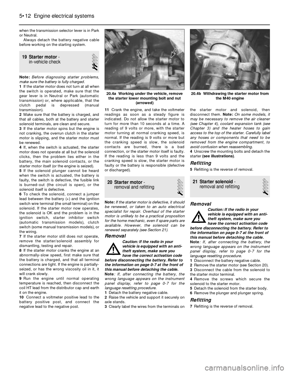
3Clearly label the wires from the terminals onthe starter motor and solenoid, then
disconnect them. Note: On some models, it
may be necessary to remove the air cleaner
(see Chapter 4), coolant expansion tank (see
Chapter 3) and the heater hoses to gain
access to the top of the starter. Carefully label
any hoses or components that need to be
removed from the engine compartment, to
avoid confusion when reassembling.
4Unscrew the mounting bolts and detach the
starter (see illustrations).
Refitting
5Refitting is the reverse of removal.
21 Starter solenoid-
removal and refitting
1
Removal
Caution: If the radio in your
vehicle is equipped with an anti-
theft system, make sure you
have the correct activation code
before disconnecting the battery. Refer to
the information on page 0-7 at the front of
this manual before detaching the cable.
Note: If, after connecting the battery, the
wrong language appears on the instrument
panel display, refer to page 0-7 for the
language resetting procedure.
1Disconnect the battery negative cable.
2Remove the starter motor (see Section 20).
3Disconnect the cable from the solenoid to
the starter motor terminal.
4Remove the screws which secure the
solenoid to the starter motor.
5Detach the solenoid from the starter body.
6Remove the plunger and plunger spring.
Refitting
7Refitting is the reverse of removal.
5•12 Engine electrical systems
20.4b Withdrawing the starter motor from
the M40 engine20.4a Working under the vehicle, remove
the starter lower mounting bolt and nut
(arrowed)
Page 125 of 228
Check
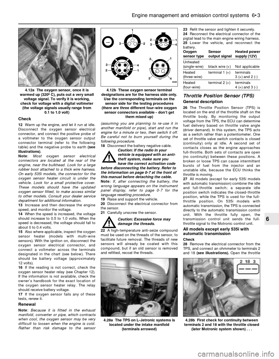
12Warm up the engine, and let it run at idle.
Disconnect the oxygen sensor electrical
connector, and connect the positive probe of
a voltmeter to the oxygen sensor output
connector terminal (refer to the following
table) and the negative probe to earth (see
illustrations).
Note:Most oxygen sensor electrical
connectors are located at the rear of the
engine, near the bulkhead. Look for a large
rubber boot attached to a thick wire harness.
On early 535i models, the connector for the
oxygen sensor heater circuit is under the
vehicle. Look for a small protective cover.
These models should have the updated
oxygen sensor fitted, to make access similar
to other models. Consult your dealer service
department for additional information.
13Increase and then decrease the engine
speed, and monitor the voltage.
14When the speed is increased, the voltage
should increase to 0.5 to 1.0 volts. When the
speed is decreased, the voltage should fall to
about 0 to 0.4 volts.
15Also where applicable, inspect the oxygen
sensor heater (models with multi-wire
sensors). With the ignition on, disconnect the
oxygen sensor electrical connector, and
connect a voltmeter across the terminals
designated in the chart (see below). There
should be battery voltage (approximately
12 volts).
16If the reading is not correct, check the
oxygen sensor heater relay (see Chapter 12).
If the information is not available, check the
owner’s handbook for the exact location of
the oxygen sensor heater relay. The relay
should receive battery voltage.
17If the oxygen sensor fails any of these
tests, renew it.
Renewal
Note: Because it is fitted in the exhaust
manifold, converter or pipe, which contracts
when cool, the oxygen sensor may be very
difficult to loosen when the engine is cold.
Rather than risk damage to the sensor(assuming you are planning to re-use it in
another manifold or pipe), start and run the
engine for a minute or two, then switch it off.
Be careful not to burn yourself during the
following procedure.
18Disconnect the battery negative cable.
Caution: If the radio in your
vehicle is equipped with an anti-
theft system, make sure you
have the correct activation code
before disconnecting the battery. Refer to
the information on page 0-7 at the front of
this manual before detaching the cable.
Note: If, after connecting the battery, the
wrong language appears on the instrument
panel display, refer to page 0-7 for the
language resetting procedure.
19Raise and support the vehicle.
20Disconnect the electrical connector from
the sensor.
21Carefully unscrew the sensor.
Caution: Excessive force may
damage the threads.
22A high-temperature anti-seize compound
must be used on the threads of the sensor, to
facilitate future removal. The threads of new
sensors will already be coated with this
compound, but if an old sensor is removed
and refitted, recoat the threads.23Refit the sensor and tighten it securely.
24Reconnect the electrical connector of the
pigtail lead to the main engine wiring harness.
25Lower the vehicle, and reconnect the
battery.
Oxygen Sensor Heated power
sensor type output signal supply (12V)
Unheated
(single-wire) black wire (+) Not applicable
Heated terminal 1 (+) terminals
(three-wire) 3 (+) and 2 (-)
Heated terminal 2 (+) terminals
(four-wire) 4 (+) and 3 (-)
Throttle Position Sensor (TPS)
General description
26The Throttle Position Sensor (TPS) is
located on the end of the throttle shaft on the
throttle body. By monitoring the output
voltage from the TPS, the ECU can determine
fuel delivery based on throttle valve angle
(driver demand). In this system, the TPS acts
as a switch rather than a potentiometer. One
set of throttle valve switch contacts is closed
(continuity) only at idle. A second set of
contacts closes as the engine approaches
full-throttle. Both sets of contacts are open
(no continuity) between these positions. A
broken or loose TPS can cause intermittent
bursts of fuel from the injector and an
unstable idle, because the ECU thinks the
throttle is moving.
27All models (except for early 535i models
with automatic transmission) combine the idle
and full-throttle switch; a separate idle
position switch indicates the closed-throttle
position, while the TPS is used for the full-
throttle position. On 535i models with
automatic transmission, the TPS is connected
directly to the automatic transmission control
unit. With the throttle fully open, the
transmission control unit sends the full-
throttle signal to the Motronic control unit.
All models except early 535i with
automatic transmission
Check
28Remove the electrical connector from the
TPS, and connect an ohmmeter to terminals 2
and 18 (see illustrations). Open the throttle
Engine management and emission control systems 6•3
4.12b These oxygen sensor terminal
designations are for the harness side only.
Use the corresponding terminals on the
sensor side for the testing procedures
(there are three different four-wire oxygen
sensor connectors available - don’t get
them mixed up)4.12a The oxygen sensor, once it is
warmed up (320º C), puts out a very small
voltage signal. To verify it is working,
check for voltage with a digital voltmeter
(the voltage signals usually range from
0.1 to 1.0 volt)
4.28b First check for continuity between
terminals 2 and 18 with the throttle closed
(later Motronic system shown) . . .4.28a The TPS on L-Jetronic systems is
located under the intake manifold
(terminals arrowed)
6
Page 136 of 228
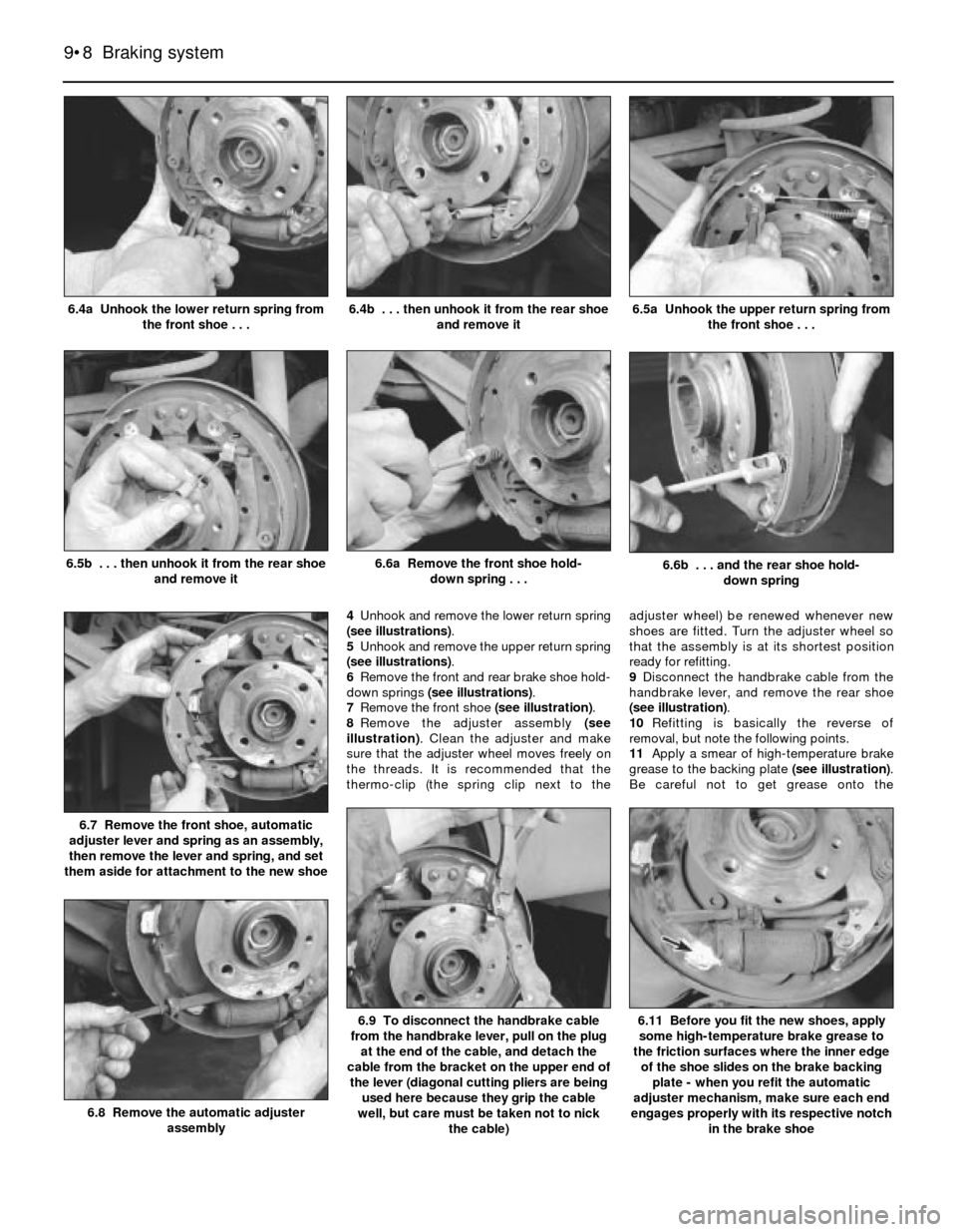
4Unhook and remove the lower return spring
(see illustrations).
5Unhook and remove the upper return spring
(see illustrations).
6Remove the front and rear brake shoe hold-
down springs (see illustrations).
7Remove the front shoe (see illustration).
8Remove the adjuster assembly (see
illustration). Clean the adjuster and make
sure that the adjuster wheel moves freely on
the threads. It is recommended that the
thermo-clip (the spring clip next to theadjuster wheel) be renewed whenever new
shoes are fitted. Turn the adjuster wheel so
that the assembly is at its shortest position
ready for refitting.
9Disconnect the handbrake cable from the
handbrake lever, and remove the rear shoe
(see illustration).
10Refitting is basically the reverse of
removal, but note the following points.
11Apply a smear of high-temperature brake
grease to the backing plate (see illustration).
Be careful not to get grease onto the
9•8 Braking system
6.11 Before you fit the new shoes, apply
some high-temperature brake grease to
the friction surfaces where the inner edge
of the shoe slides on the brake backing
plate - when you refit the automatic
adjuster mechanism, make sure each end
engages properly with its respective notch
in the brake shoe6.9 To disconnect the handbrake cable
from the handbrake lever, pull on the plug
at the end of the cable, and detach the
cable from the bracket on the upper end of
the lever (diagonal cutting pliers are being
used here because they grip the cable
well, but care must be taken not to nick
the cable)
6.8 Remove the automatic adjuster
assembly
6.7 Remove the front shoe, automatic
adjuster lever and spring as an assembly,
then remove the lever and spring, and set
them aside for attachment to the new shoe
6.6b . . . and the rear shoe hold-
down spring6.6a Remove the front shoe hold-
down spring . . .6.5b . . . then unhook it from the rear shoe
and remove it
6.5a Unhook the upper return spring from
the front shoe . . .6.4b . . . then unhook it from the rear shoe
and remove it6.4a Unhook the lower return spring from
the front shoe . . .
Page 137 of 228
friction surfaces of the brake shoes or
drums.
12Make sure the adjuster assembly is
properly engaged with its respective notch in
the handbrake lever.
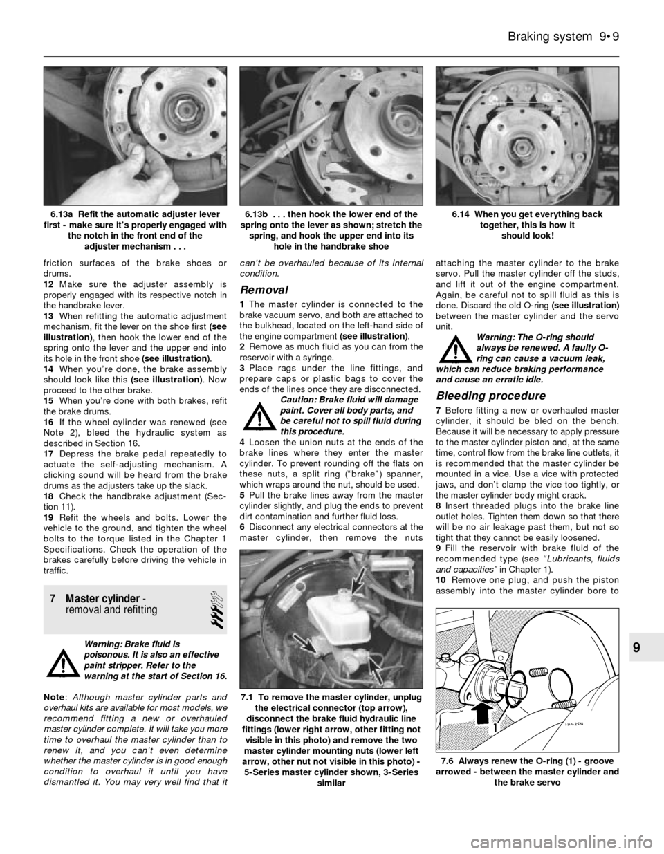
13When refitting the automatic adjustment
mechanism, fit the lever on the shoe first (see
illustration), then hook the lower end of the
spring onto the lever and the upper end into
its hole in the front shoe (see illustration).
14When you’re done, the brake assembly
should look like this (see illustration). Now
proceed to the other brake.
15When you’re done with both brakes, refit
the brake drums.
16If the wheel cylinder was renewed (see
Note 2), bleed the hydraulic system as
described in Section 16.
17Depress the brake pedal repeatedly to
actuate the self-adjusting mechanism. A
clicking sound will be heard from the brake
drums as the adjusters take up the slack.
18Check the handbrake adjustment (Sec-
tion 11).
19Refit the wheels and bolts. Lower the
vehicle to the ground, and tighten the wheel
bolts to the torque listed in the Chapter 1
Specifications. Check the operation of the
brakes carefully before driving the vehicle in
traffic.
7 Master cylinder-
removal and refitting
3
Warning: Brake fluid is
poisonous. It is also an effective
paint stripper. Refer to the
warning at the start of Section 16.
Note: Although master cylinder parts and
overhaul kits are available for most models, we
recommend fitting a new or overhauled
master cylinder complete. It will take you more
time to overhaul the master cylinder than to
renew it, and you can’t even determine
whether the master cylinder is in good enough
condition to overhaul it until you have
dismantled it. You may very well find that itcan’t be overhauled because of its internal
condition.
Removal
1The master cylinder is connected to the
brake vacuum servo, and both are attached to
the bulkhead, located on the left-hand side of
the engine compartment (see illustration).
2Remove as much fluid as you can from the
reservoir with a syringe.
3Place rags under the line fittings, and
prepare caps or plastic bags to cover the
ends of the lines once they are disconnected.
Caution: Brake fluid will damage
paint. Cover all body parts, and
be careful not to spill fluid during
this procedure.
4Loosen the union nuts at the ends of the
brake lines where they enter the master
cylinder. To prevent rounding off the flats on
these nuts, a split ring (“brake”) spanner,
which wraps around the nut, should be used.
5Pull the brake lines away from the master
cylinder slightly, and plug the ends to prevent
dirt contamination and further fluid loss.
6Disconnect any electrical connectors at the
master cylinder, then remove the nutsattaching the master cylinder to the brake
servo. Pull the master cylinder off the studs,
and lift it out of the engine compartment.
Again, be careful not to spill fluid as this is
done. Discard the old O-ring (see illustration)
between the master cylinder and the servo
unit.
Warning: The O-ring should
always be renewed. A faulty O-
ring can cause a vacuum leak,
which can reduce braking performance
and cause an erratic idle.
Bleeding procedure
7Before fitting a new or overhauled master
cylinder, it should be bled on the bench.
Because it will be necessary to apply pressure
to the master cylinder piston and, at the same
time, control flow from the brake line outlets, it
is recommended that the master cylinder be
mounted in a vice. Use a vice with protected
jaws, and don’t clamp the vice too tightly, or
the master cylinder body might crack.
8Insert threaded plugs into the brake line
outlet holes. Tighten them down so that there
will be no air leakage past them, but not so
tight that they cannot be easily loosened.
9Fill the reservoir with brake fluid of the
recommended type (see “Lubricants, fluids
and capacities” in Chapter 1).
10Remove one plug, and push the piston
assembly into the master cylinder bore to
Braking system 9•9
6.14 When you get everything back
together, this is how it
should look! 6.13b . . . then hook the lower end of the
spring onto the lever as shown; stretch the
spring, and hook the upper end into its
hole in the handbrake shoe6.13a Refit the automatic adjuster lever
first - make sure it’s properly engaged with
the notch in the front end of the
adjuster mechanism . . .
7.6 Always renew the O-ring (1) - groove
arrowed - between the master cylinder and
the brake servo
7.1 To remove the master cylinder, unplug
the electrical connector (top arrow),
disconnect the brake fluid hydraulic line
fittings (lower right arrow, other fitting not
visible in this photo) and remove the two
master cylinder mounting nuts (lower left
arrow, other nut not visible in this photo) -
5-Series master cylinder shown, 3-Series
similar
9
Page 142 of 228
simply unscrew it. Plug the open fitting in the
caliper if the hose is removed for any length of
time, to prevent dirt ingress.
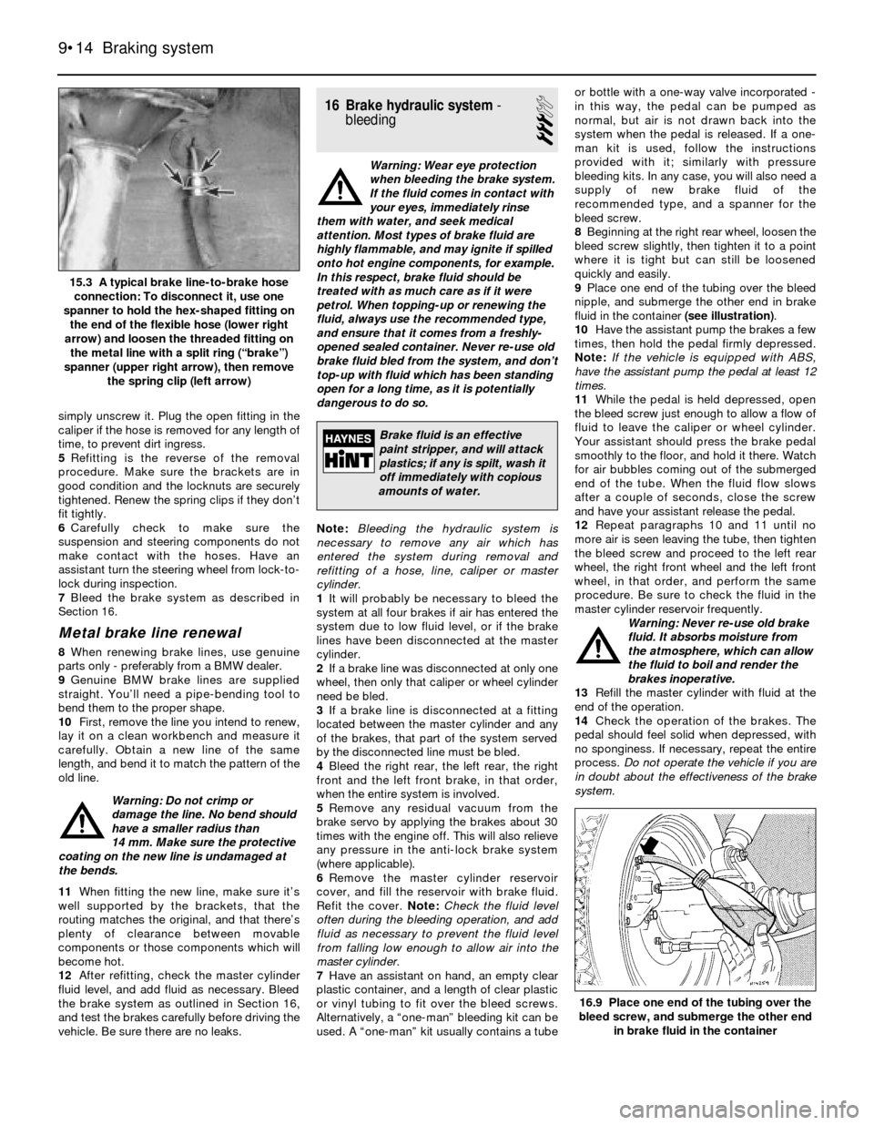
5Refitting is the reverse of the removal
procedure. Make sure the brackets are in
good condition and the locknuts are securely
tightened. Renew the spring clips if they don’t
fit tightly.
6Carefully check to make sure the
suspension and steering components do not
make contact with the hoses. Have an
assistant turn the steering wheel from lock-to-
lock during inspection.
7Bleed the brake system as described in
Section 16.
Metal brake line renewal
8When renewing brake lines, use genuine
parts only - preferably from a BMW dealer.
9Genuine BMW brake lines are supplied
straight. You’ll need a pipe-bending tool to
bend them to the proper shape.
10First, remove the line you intend to renew,
lay it on a clean workbench and measure it
carefully. Obtain a new line of the same
length, and bend it to match the pattern of the
old line.
Warning: Do not crimp or
damage the line. No bend should
have a smaller radius than
14 mm. Make sure the protective
coating on the new line is undamaged at
the bends.
11When fitting the new line, make sure it’s
well supported by the brackets, that the
routing matches the original, and that there’s
plenty of clearance between movable
components or those components which will
become hot.
12After refitting, check the master cylinder
fluid level, and add fluid as necessary. Bleed
the brake system as outlined in Section 16,
and test the brakes carefully before driving the
vehicle. Be sure there are no leaks.
16 Brake hydraulic system-
bleeding
3
Warning: Wear eye protection
when bleeding the brake system.
If the fluid comes in contact with
your eyes, immediately rinse
them with water, and seek medical
attention. Most types of brake fluid are
highly flammable, and may ignite if spilled
onto hot engine components, for example.
In this respect, brake fluid should be
treated with as much care as if it were
petrol. When topping-up or renewing the
fluid, always use the recommended type,
and ensure that it comes from a freshly-
opened sealed container. Never re-use old
brake fluid bled from the system, and don’t
top-up with fluid which has been standing
open for a long time, as it is potentially
dangerous to do so.
Note:Bleeding the hydraulic system is
necessary to remove any air which has
entered the system during removal and
refitting of a hose, line, caliper or master
cylinder.
1It will probably be necessary to bleed the
system at all four brakes if air has entered the
system due to low fluid level, or if the brake
lines have been disconnected at the master
cylinder.
2If a brake line was disconnected at only one
wheel, then only that caliper or wheel cylinder
need be bled.
3If a brake line is disconnected at a fitting
located between the master cylinder and any
of the brakes, that part of the system served
by the disconnected line must be bled.
4Bleed the right rear, the left rear, the right
front and the left front brake, in that order,
when the entire system is involved.
5Remove any residual vacuum from the
brake servo by applying the brakes about 30
times with the engine off. This will also relieve
any pressure in the anti-lock brake system
(where applicable).
6Remove the master cylinder reservoir
cover, and fill the reservoir with brake fluid.
Refit the cover. Note:Check the fluid level
often during the bleeding operation, and add
fluid as necessary to prevent the fluid level
from falling low enough to allow air into the
master cylinder.
7Have an assistant on hand, an empty clear
plastic container, and a length of clear plastic
or vinyl tubing to fit over the bleed screws.
Alternatively, a “one-man” bleeding kit can be
used. A “one-man” kit usually contains a tubeor bottle with a one-way valve incorporated -
in this way, the pedal can be pumped as
normal, but air is not drawn back into the
system when the pedal is released. If a one-
man kit is used, follow the instructions
provided with it; similarly with pressure
bleeding kits. In any case, you will also need a
supply of new brake fluid of the
recommended type, and a spanner for the
bleed screw.
8Beginning at the right rear wheel, loosen the
bleed screw slightly, then tighten it to a point
where it is tight but can still be loosened
quickly and easily.
9Place one end of the tubing over the bleed
nipple, and submerge the other end in brake
fluid in the container (see illustration).
10Have the assistant pump the brakes a few
times, then hold the pedal firmly depressed.
Note:If the vehicle is equipped with ABS,
have the assistant pump the pedal at least 12
times.
11While the pedal is held depressed, open
the bleed screw just enough to allow a flow of
fluid to leave the caliper or wheel cylinder.
Your assistant should press the brake pedal
smoothly to the floor, and hold it there. Watch
for air bubbles coming out of the submerged
end of the tube. When the fluid flow slows
after a couple of seconds, close the screw
and have your assistant release the pedal.
12Repeat paragraphs 10 and 11 until no
more air is seen leaving the tube, then tighten
the bleed screw and proceed to the left rear
wheel, the right front wheel and the left front
wheel, in that order, and perform the same
procedure. Be sure to check the fluid in the
master cylinder reservoir frequently.
Warning: Never re-use old brake
fluid. It absorbs moisture from
the atmosphere, which can allow
the fluid to boil and render the
brakes inoperative.
13Refill the master cylinder with fluid at the
end of the operation.
14Check the operation of the brakes. The
pedal should feel solid when depressed, with
no sponginess. If necessary, repeat the entire
process. Do not operate the vehicle if you are
in doubt about the effectiveness of the brake
system.
9•14 Braking system
16.9 Place one end of the tubing over the
bleed screw, and submerge the other end
in brake fluid in the container
15.3 A typical brake line-to-brake hose
connection: To disconnect it, use one
spanner to hold the hex-shaped fitting on
the end of the flexible hose (lower right
arrow) and loosen the threaded fitting on
the metal line with a split ring (“brake”)
spanner (upper right arrow), then remove
the spring clip (left arrow)
Brake fluid is an effective
paint stripper, and will attack
plastics; if any is spilt, wash it
off immediately with copious
amounts of water.
Page 155 of 228
Where power-assistance is fitted, hydraulic
pressure (provided by an engine-driven pump)
delivers power steering fluid to the rack-and-
pinion steering gear or the recirculating-ball
steering box - this enhances steering
response and reduces steering effort.
Aside from maintaining the proper level of
power steering fluid in the system and
checking the tension of the drivebelt (see
Chapter 1, where applicable), the steering
system requires no maintenance. However,
on high-mileage vehicles, the track rod end
balljoints, the universal joints on either end of
the universal joint shaft, and the rubber
coupling between the steering column and the
universal joint shaft will wear, develop
excessive play, and cause the steering to feel
somewhat loose. At this point, you’ll have to
renew these items; they can’t be serviced.
Before you conclude that the steering
system needs work, however, always check
the tyres (see Section 25) and tyre pressures
(see Chapter 1). Also inspect the bearings in
the strut upper mounts (see Section 5), the
front hub bearings (see Section 8) and other
suspension parts, which may also be
contributing to an imprecise steering feel.
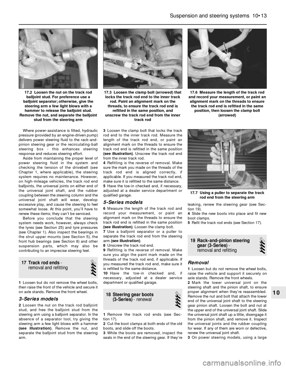
17 Track rod ends-
removal and refitting
4
1Loosen but do not remove the wheel bolts,
then raise the front of the vehicle and secure it
on axle stands. Remove the front wheel.
3-Series models
2Loosen the nut on the track rod balljoint
stud, and free the balljoint stud from the
steering arm using a balljoint separator. In the
absence of a separator tool, try giving the
steering arm a few light blows with a hammer
(see illustration). Remove the nut, and
separate the balljoint stud from the steering
arm.3Loosen the clamp bolt that locks the track
rod end to the inner track rod. Measure the
length of the track rod end, or paint an
alignment mark on the threads to ensure the
track rod end is refitted in the same position
(see illustration). Unscrew the track rod end
from the inner track rod.
4Refitting is the reverse of removal. Make
sure the mark you made on the threads of the
track rod end is aligned correctly, if
applicable. If you measured the track rod end,
make sure it is refitted to the same distance.
5Have the toe-in checked and, if necessary,
adjusted at a dealer service department or
qualified garage.
5-Series models
6Measure the length of the track rod and
record your measurement, or paint an
alignment mark on the threads to ensure the
track rod end is refitted in the same position
(see illustration). Loosen the clamp bolt.
7Use a balljoint separator or a puller to
separate the track rod end from the steering
arm (see illustration).
8Unscrew the track rod end.
9Refitting is the reverse of removal. Make
sure you align the paint mark made on the
threads of the track rod end, if applicable. If
you measured the track rod end, make sure it
is refitted to the same distance.
10Have the toe-in checked and, if
necessary, adjusted at a dealer service
department or qualified garage.
18 Steering gear boots
(3-Series)- renewal
4
1Remove the track rod ends (see Sec-
tion 17).
2Cut the boot clamps at both ends of the old
boots, and slide off the boots.
3While the boots are removed, inspect the
seals in the end of the steering gear. If they’releaking, renew the steering gear (see Sec-
tion 19).
4Slide the new boots into place and fit new
boot clamps.
5Refit the track rod ends (see Section 17).
19 Rack-and-pinion steering
gear (3-Series)-
removal and refitting
4
Removal
1Loosen but do not remove the wheel bolts,
raise the vehicle and support it securely on
axle stands. Remove the front wheels.
2Mark the lower universal joint on the
steering shaft and the pinion shaft, to ensure
proper alignment when they’re reassembled.
Remove the nut and bolt that attach the lower
end of the universal joint shaft to the steering
gear pinion shaft. Loosen the bolt and nut at
the upper end of the universal joint shaft. Slide
the universal joint shaft up a little, disengage it
from the pinion shaft, and remove it. Inspect
the universal joints and the rubber coupling
for wear. If any of them are worn or defective,
renew the universal joint shaft.
3On power steering models, using a large
Suspension and steering systems 10•13
17.6 Measure the length of the track rod
and record your measurement, or paint an
alignment mark on the threads to ensure
the track rod end is refitted in the same
position, then loosen the clamp bolt
(arrowed)17.3 Loosen the clamp bolt (arrowed) that
locks the track rod end to the inner track
rod. Paint an alignment mark on the
threads, to ensure the track rod end is
refitted in the same position, and
unscrew the track rod end from the inner
track rod17.2 Loosen the nut on the track rod
balljoint stud. For preference use a
balljoint separator; otherwise, give the
steering arm a few light blows with a
hammer to release the balljoint stud.
Remove the nut, and separate the balljoint
stud from the steering arm
17.7 Using a puller to separate the track
rod end from the steering arm
10
Page 156 of 228
syringe or hand pump, empty the power
steering fluid reservoir.
4On power steering models, remove the
banjo bolts and disconnect the power
steering pressure and return lines from the
steering gear. Place a container under the
lines to catch spilled fluid. Plug the lines to
prevent excessive fluid loss and
contamination. Discard the sealing washers
(new ones should be used when
reassembling).
5Disconnect the track rod ends from the
steering arms (see Section 17).
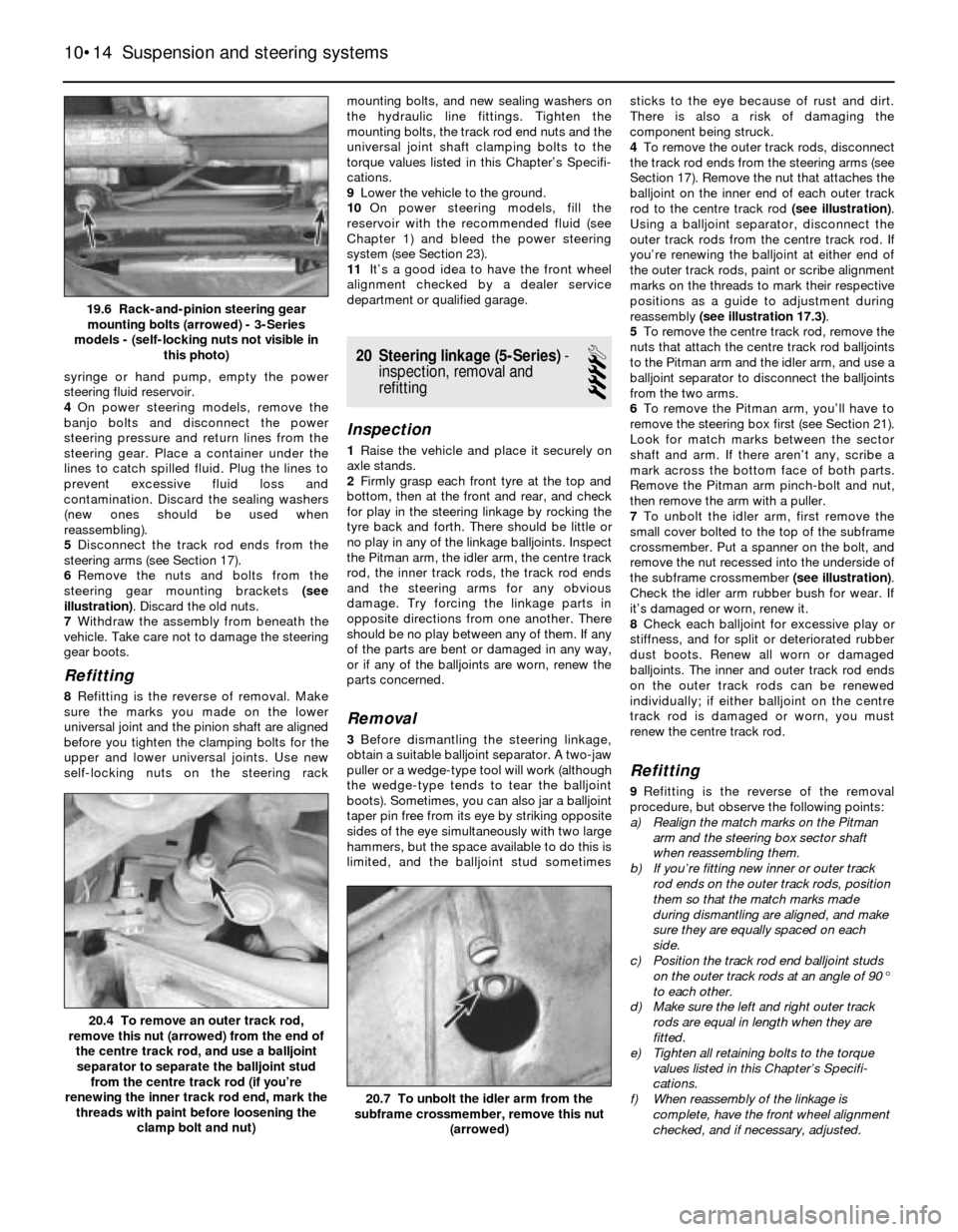
6Remove the nuts and bolts from the
steering gear mounting brackets (see
illustration). Discard the old nuts.
7Withdraw the assembly from beneath the
vehicle. Take care not to damage the steering
gear boots.
Refitting
8Refitting is the reverse of removal. Make
sure the marks you made on the lower
universal joint and the pinion shaft are aligned
before you tighten the clamping bolts for the
upper and lower universal joints. Use new
self-locking nuts on the steering rackmounting bolts, and new sealing washers on
the hydraulic line fittings. Tighten the
mounting bolts, the track rod end nuts and the
universal joint shaft clamping bolts to the
torque values listed in this Chapter’s Specifi-
cations.
9Lower the vehicle to the ground.
10On power steering models, fill the
reservoir with the recommended fluid (see
Chapter 1) and bleed the power steering
system (see Section 23).
11It’s a good idea to have the front wheel
alignment checked by a dealer service
department or qualified garage.
20 Steering linkage (5-Series)-
inspection, removal and
refitting
4
Inspection
1Raise the vehicle and place it securely on
axle stands.
2Firmly grasp each front tyre at the top and
bottom, then at the front and rear, and check
for play in the steering linkage by rocking the
tyre back and forth. There should be little or
no play in any of the linkage balljoints. Inspect
the Pitman arm, the idler arm, the centre track
rod, the inner track rods, the track rod ends
and the steering arms for any obvious
damage. Try forcing the linkage parts in
opposite directions from one another. There
should be no play between any of them. If any
of the parts are bent or damaged in any way,
or if any of the balljoints are worn, renew the
parts concerned.
Removal
3Before dismantling the steering linkage,
obtain a suitable balljoint separator. A two-jaw
puller or a wedge-type tool will work (although
the wedge-type tends to tear the balljoint
boots). Sometimes, you can also jar a balljoint
taper pin free from its eye by striking opposite
sides of the eye simultaneously with two large
hammers, but the space available to do this is
limited, and the balljoint stud sometimessticks to the eye because of rust and dirt.
There is also a risk of damaging the
component being struck.
4To remove the outer track rods, disconnect
the track rod ends from the steering arms (see
Section 17). Remove the nut that attaches the
balljoint on the inner end of each outer track
rod to the centre track rod (see illustration).
Using a balljoint separator, disconnect the
outer track rods from the centre track rod. If
you’re renewing the balljoint at either end of
the outer track rods, paint or scribe alignment
marks on the threads to mark their respective
positions as a guide to adjustment during
reassembly (see illustration 17.3).
5To remove the centre track rod, remove the
nuts that attach the centre track rod balljoints
to the Pitman arm and the idler arm, and use a
balljoint separator to disconnect the balljoints
from the two arms.
6To remove the Pitman arm, you’ll have to
remove the steering box first (see Section 21).
Look for match marks between the sector
shaft and arm. If there aren’t any, scribe a
mark across the bottom face of both parts.
Remove the Pitman arm pinch-bolt and nut,
then remove the arm with a puller.
7To unbolt the idler arm, first remove the
small cover bolted to the top of the subframe
crossmember. Put a spanner on the bolt, and
remove the nut recessed into the underside of
the subframe crossmember (see illustration).
Check the idler arm rubber bush for wear. If
it’s damaged or worn, renew it.
8Check each balljoint for excessive play or
stiffness, and for split or deteriorated rubber
dust boots. Renew all worn or damaged
balljoints. The inner and outer track rod ends
on the outer track rods can be renewed
individually; if either balljoint on the centre
track rod is damaged or worn, you must
renew the centre track rod.
Refitting
9Refitting is the reverse of the removal
procedure, but observe the following points:
a) Realign the match marks on the Pitman
arm and the steering box sector shaft
when reassembling them.
b) If you’re fitting new inner or outer track
rod ends on the outer track rods, position
them so that the match marks made
during dismantling are aligned, and make
sure they are equally spaced on each
side.
c) Position the track rod end balljoint studs
on the outer track rods at an angle of 90°
to each other.
d) Make sure the left and right outer track
rods are equal in length when they are
fitted.
e) Tighten all retaining bolts to the torque
values listed in this Chapter’s Specifi-
cations.
f) When reassembly of the linkage is
complete, have the front wheel alignment
checked, and if necessary, adjusted.
10•14 Suspension and steering systems
20.7 To unbolt the idler arm from the
subframe crossmember, remove this nut
(arrowed)
20.4 To remove an outer track rod,
remove this nut (arrowed) from the end of
the centre track rod, and use a balljoint
separator to separate the balljoint stud
from the centre track rod (if you’re
renewing the inner track rod end, mark the
threads with paint before loosening the
clamp bolt and nut)
19.6 Rack-and-pinion steering gear
mounting bolts (arrowed) - 3-Series
models - (self-locking nuts not visible in
this photo)