Light switch BMW 3 SERIES 1984 E30 Owner's Manual
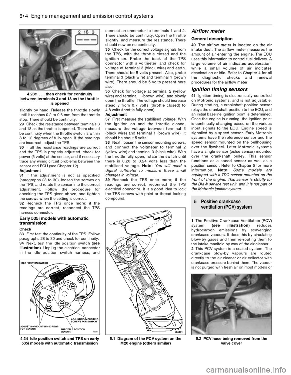
[x] Cancel search | Manufacturer: BMW, Model Year: 1984, Model line: 3 SERIES, Model: BMW 3 SERIES 1984 E30Pages: 228, PDF Size: 7.04 MB
Page 107 of 228
2L-Jetronic systems are equipped with a
separate idle speed control unit (computer)
located under the facia. The idle air stabiliser
valve has an adjusting screw. Early models
are equipped with plastic valves, but they still
can be adjusted by removing the hose and
inserting a very thin screwdriver inside.
3Early Motronic systems are also equipped
with a separate idle speed control unit
(computer) located under the facia. The idle
air stabiliser valve has an adjusting screw.
4On later Motronic systems, the idle air
stabiliser valve is ECU-controlled, and no
provision is made for adjustment.
Preliminary check
5Before performing any checks on the idle
air stabiliser valve, make sure these criteria
are met:
a) The engine must be at operating
temperature (60ºC)
b) Turn off all electrical accessories (air
conditioning, heater controls, headlights,
auxiliary cooling fan, etc)
c) The throttle position sensor must be
operating correctly (see Chapter 6)
d) There must not be any exhaust leaks
e) There must not be any vacuum leaks
f) Where fitted, the oxygen sensor must be
operating properly (see Chapter 6)
6Connect a tachometer in accordance with
the manufacturer’s instructions.
Caution: The ignition must be
switched off before making any
electrical connections.
7The idle air stabiliser valve operates
continuously when the ignition is on. Start the
engine and make sure the valve is vibrating
and humming slightly.
L-Jetronic system
Check
8With the engine running, disconnect the
electrical connector from the valve. The idle
speed should increase to about 2,000 rpm.
9If the idle speed does not increase, turn the
engine off. Using an ohmmeter, check the
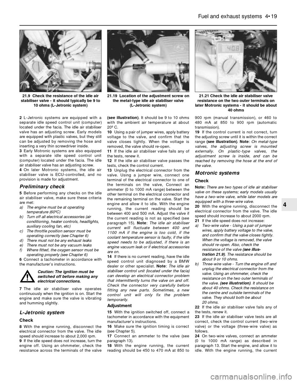
resistance across the terminals of the valve(see illustration). It should be 9 to 10 ohms
with the ambient air temperature at about
20º C.
10Using a pair of jumper wires, apply battery
voltage to the valve, and confirm that the
valve closes tightly. When the voltage is
removed, the valve should re-open.
11If the idle air stabiliser valve fails any of
the tests, renew it.
12If the idle air stabiliser valve passes the
tests, check the control current.
13Unplug the electrical connector from the
valve. Using a jumper wire, connect one
terminal of the electrical connector to one of
the terminals on the valve, Connect an
ammeter (0 to 1000 mA range) between the
other terminal on the electrical connector and
the remaining terminal on the valve. Start the
engine and allow it to idle. With the engine
running, the current reading should be
between 400 and 500 mA. Adjust the valve if
the current reading is not as specified (see
paragraph 15). Note: The idle air stabiliser
current will fluctuate between 400 and
1100 mA if the engine is too cold, if the
coolant temperature sensor is faulty, if the idle
speed needs to be adjusted, if there is an
engine vacuum leak or if electrical accessories
are on.
14If there is no current reading, have the idle
speed control unit diagnosed by a BMW
dealer or other specialist. Note: The idle air
stabiliser control unit (located under the facia)
can develop an electrical connector problem
that intermittently turns the valve on and off.
Check the connector very carefully before
fitting any new parts. Sometimes, a new
control unit will only fix the problem
temporarily.
Adjustment
15With the ignition switched off, connect a
tachometer in accordance with the equipment
manufacturer’s instructions.
16Make sure the ignition timing is correct
(see Chapter 5).
17Connect an ammeter to the valve (see
paragraph 13).
18With the engine running, the current
reading should be 450 to 470 mA at 850 to900 rpm (manual transmission), or 460 to
480 mA at 850 to 900 rpm (automatic
transmission).
19If the control current is not correct, turn
the adjusting screw until it is within the correct
range (see illustration). Note: On metal-type
valves, the adjusting screw is mounted
externally. On plastic-type valves, the
adjustment screw is inside, and can be
reached by removing the hose at the end of
the valve.
Motronic systems
Check
Note:There are two types of idle air stabiliser
valve on these systems; early models usually
have a two-wire valve, while later models are
equipped with a three-wire valve.
20With the engine running, disconnect the
electrical connector from the valve. The idle
speed should increase to about 2000 rpm.
21If the idle speed does not increase:
a) Two-wire valve - Using a pair of jumper
wires, apply battery voltage to the valve,
and confirm that the valve closes tightly.
When the voltage is removed, the valve
should re-open. Also, check the
resistance of the valve (see illus-
tration 21.9). The resistance should be
about 9 or 10 ohms.
b) Three-wire valve - Turn the engine off and
unplug the electrical connector from the
valve. Using an ohmmeter, check the
resistance on the two outer terminals of
the valve. (see illustration). It should be
about 40 ohms. Check the resistance on
the centre and outside terminals of the
valve. They should both be about
20 ohms.
22If the idle air stabiliser valve fails any of
the tests, renew it.
23If the idle air stabiliser valve tests are all
correct, check the control current (two-wire
valve) or the voltage (three-wire valve) as
follows.
24On two-wire valves, connect an ammeter
(0 to 1000 mA range) as described in
paragraph 13. Start the engine, and allow it to
idle. With the engine running, the current
Fuel and exhaust systems 4•19
21.21 Check the idle air stabiliser valve
resistance on the two outer terminals on
later Motronic systems - it should be about
40 ohms21.19 Location of the adjustment screw on
the metal-type idle air stabiliser valve
(L-Jetronic system)21.9 Check the resistance of the idle air
stabiliser valve - it should typically be 9 to
10 ohms (L-Jetronic system)
4
Page 112 of 228
1 General information
The engine electrical systems include all
ignition, charging and starting components.
Because of their engine-related functions,
these components are discussed separately
from body-related electrical devices such as
the lights, the instruments, etc. (which are
included in Chapter 12).
Always observe the following precautions
when working on the electrical systems:
a) Be extremely careful when servicing
engine electrical components. They are
easily damaged if improperly checked,
connected or handled.
b) Never leave the ignition switched on for
long periods of time with the engine off.
c) Don’t disconnect the battery cables while
the engine is running.
d) Observe the rules when jump-starting
your vehicle. Read the precautions at the
front of this manual.
e) Always disconnect the battery negative
cable first, and connect it last, to reduce
the risk of accidental short-circuits.
f) Don’t charge the battery with the cables
connected to the terminals.
It’s also a good idea to review the safety-
related information regarding the engine
electrical systems in the “Safety first”section
near the front of this manual before beginning
any operation included in this Chapter.
Caution: If the radio in your
vehicle is equipped with an anti-
theft system, make sure you
have the correct activation code
before disconnecting the battery. Refer to
the information on page 0-7 at the front of
this manual before detaching the cable.
Note: If, after connecting the battery, the
wrong language appears on the instrument
panel display, refer to page 0-7 for the
language resetting procedure.
2 Battery-
emergency jump starting
1
Refer to the “Jump starting”procedure at
the front of this manual.
3 Battery- removal and refitting
1
Note:Depending on the model, the battery
may be located in the engine compartment, in
the rear luggage compartment, or under the
rear seat. Consult your owners handbook for
the location of the battery, if not already
known to you.Caution: If the radio in your
vehicle is equipped with an anti-
theft system, make sure you
have the correct activation code
before disconnecting the battery. Refer to
the information on page 0-7 at the front of
this manual before detaching the cable.
Note: If, after connecting the battery, the
wrong language appears on the instrument
panel display, refer to page 0-7 for the
language resetting procedure.
1Disconnect the battery negative cable.
2Detach the cable from the positive terminal.
3Remove the battery hold-down bracket
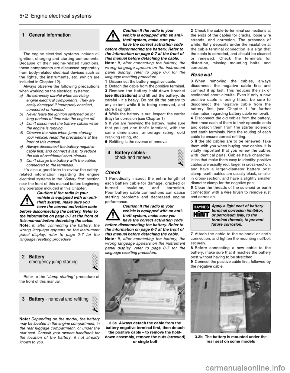
(see illustrations)and lift out the battery. Be
careful - it’s heavy. Do not tilt the battery to
any extent while it is being removed, and
store it upright.
4While the battery is out, inspect the carrier
(tray) for corrosion (see Chapter 1).
5If you are renewing the battery, make sure
that you get one that’s identical, with the
same dimensions, amperage rating, cold
cranking rating, etc.
6Refitting is the reverse of removal.
4 Battery cables-
check and renewal
1
Check
1Periodically inspect the entire length of
each battery cable for damage, cracked or
burned insulation, and corrosion.
Poor battery cable connections can cause
starting problems and decreased engine
performance.
Caution: If the radio in your
vehicle is equipped with an anti-
theft system, make sure you
have the correct activation code
before disconnecting the battery. Refer to
the information on page 0-7 at the front of
this manual before detaching the cable.
Note: If, after connecting the battery, the
wrong language appears on the instrument
panel display, refer to page 0-7 for the
language resetting procedure.2Check the cable-to-terminal connections at
the ends of the cables for cracks, loose wire
strands, and corrosion. The presence of
white, fluffy deposits under the insulation at
the cable terminal connection is a sign that
the cable is corroded, and should be cleaned
or renewed. Check the terminals for
distortion, missing mounting bolts, and
corrosion.
Renewal
3When removing the cables, always
disconnect the negative cable first and
connect it up last. This reduces the risk of
accidental short-circuits. Even if only a new
positive cable is being fitted, be sure to
disconnect the negative cable from the
battery first (see Chapter 1 for further
information regarding battery cable removal).
4Disconnect the old cables from the battery,
then trace each of them to their opposite ends
and detach them from the starter solenoid
and earth terminals. Note the routing of each
cable to ensure correct refitting.
5If the old cables are to be renewed, take
them with you when buying new cables. It is
vitally important that you renew the cables
with identical parts. Cables have character-
istics that make them easy to identify: positive
cables are usually red, larger in cross-section,
and have a larger-diameter battery post
clamp; earth cables are usually black, smaller
in cross-section, and have a slightly smaller
diameter clamp for the negative post.
6Clean the threads of the solenoid or earth
connection with a wire brush to remove rust
and corrosion.
7Attach the cable to the solenoid or earth
connection, and tighten the mounting nut/bolt
securely.
8Before connecting a new cable to the
battery, make sure that it reaches the battery
post without having to be stretched.
9Connect the positive cable first, followed by
the negative cable.
5•2 Engine electrical systems
3.3b The battery is mounted under the
rear seat on some models
3.3a Always detach the cable from the
battery negative terminal first, then detach
the positive cable – to remove the hold-
down assembly, remove the nuts (arrowed)
or single bolt
Apply a light coat of battery
terminal corrosion inhibitor,
or petroleum jelly, to the
terminal threads, to prevent
future corrosion.
Page 114 of 228
7 Ignition timing (TCI system)-
check and adjustment
4
Warning: Keep hands, equipment
and wires well clear of the
viscous cooling fan during
adjustment of the ignition timing.
Note:This Section describes the procedure
for checking and adjusting the ignition timing
on engines fitted with the TCI system. On
engines fitted with the Motronic engine
management system, the ignition timing is
controlled by the electronic control unit, and
no adjustment is possible. The timing can be
checked using the following procedure, but no
ignition timing values were available at the
time of writing. If the timing is thought to be
incorrect, refer to a BMW dealer.
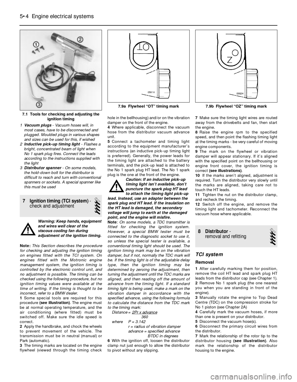
1Some special tools are required for this
procedure (see illustration). The engine must
be at normal operating temperature, and the
air conditioning (where fitted) must be
switched off. Make sure the idle speed is
correct.
2Apply the handbrake, and chock the wheels
to prevent movement of the vehicle. The
transmission must be in neutral (manual) or
Park (automatic).
3The timing marks are located on the engine
flywheel (viewed through the timing checkhole in the bellhousing) and/or on the vibration
damper on the front of the engine.
4Where applicable, disconnect the vacuum
hose from the distributor vacuum advance
unit.
5Connect a tachometer and timing light
according to the equipment manufacturer’s
instructions (an inductive pick-up timing light
is preferred). Generally, the power leads for
the timing light are attached to the battery
terminals, and the pick-up lead is attached to
the No 1 spark plug HT lead. The No 1 spark
plug is the one at the front of the engine.
Caution: If an inductive pick-up
timing light isn’t available, don’t
puncture the spark plug HT lead
to attach the timing light pick-up
lead. Instead, use an adapter between the
spark plug and HT lead. If the insulation on
the HT lead is damaged, the secondary
voltage will jump to earth at the damaged
point, and the engine will misfire.
Note:On some models, a TDC transmitter is
fitted for checking the ignition system.
However, a special BMW tester must be
connected to the diagnostic socket to use it,
so unless the special tester is available, a
conventional timing light should be used. The
ignition timing mark may be on the vibration
damper, but if not, normally the TDC mark will
be. If the timing light is of the adjustable delay
type, then the ignition timing may be
determined by zeroing the adjustment, then
turning the adjustment until the TDC marks are
aligned, and then reading off the amount of
advance from the timing light. If a standard
timing light is being used, make a mark on the
vibration damper in accordance with the
specified advance, using the following formula
to calculate the distance from the TDC mark
to the timing mark:
Distance = 2Pr x advance
360
where P = 3.142
r = radius of vibration damper
advance = specified advance
BTDC in degrees
6With the ignition off, loosen the distributor
clamp nut just enough to allow the distributor
to pivot without any slipping.7Make sure the timing light wires are routed
away from the drivebelts and fan, then start
the engine.
8Raise the engine rpm to the specified
speed, and then point the flashing timing light
at the timing marks - be very careful of moving
engine components.
9The mark on the flywheel or vibration
damper will appear stationary. If it’s aligned
with the specified point on the bellhousing or
engine front cover, the ignition timing is
correct (see illustrations).
10If the marks aren’t aligned, adjustment is
required. Turn the distributor very slowly until
the marks are aligned, taking care not to
touch the HT leads.
11Tighten the nut on the distributor clamp,
and recheck the timing.
12Switch off the engine, and remove the
timing light and tachometer. Reconnect the
vacuum hose where applicable.
8 Distributor-
removal and refitting
4
TCI system
Removal
1After carefully marking them for position,
remove the coil HT lead and spark plug HT
leads from the distributor cap (see Chapter 1).
2Remove No 1 spark plug (the one nearest
you when you are standing in front of the
engine).
3Manually rotate the engine to Top Dead
Centre (TDC) on the compression stroke for
No 1 piston (see Chapter 2A)
4Carefully mark the vacuum hoses, if more
than one is present on your distributor.
5Disconnect the vacuum hose(s).
6Disconnect the primary circuit wires from
the distributor.
7Mark the relationship of the rotor tip to the
distributor housing (see illustration). Also
mark the relationship of the distributor
housing to the engine.
5•4 Engine electrical systems
7.1 Tools for checking and adjusting the
ignition timing
1Vacuum plugs- Vacuum hoses will, in
most cases, have to be disconnected and
plugged. Moulded plugs in various shapes
and sizes can be used for this, if wished
2Inductive pick-up timing light- Flashes a
bright, concentrated beam of light when
No 1 spark plug fires. Connect the leads
according to the instructions supplied with
the light
3Distributor spanner - On some models,
the hold-down bolt for the distributor is
difficult to reach and turn with conventional
spanners or sockets. A special spanner like
this must be used
7.9a Flywheel “OT” timing mark 7.9b Flywheel “OZ” timing mark
Page 117 of 228
8Use a digital voltmeter for the following
tests:
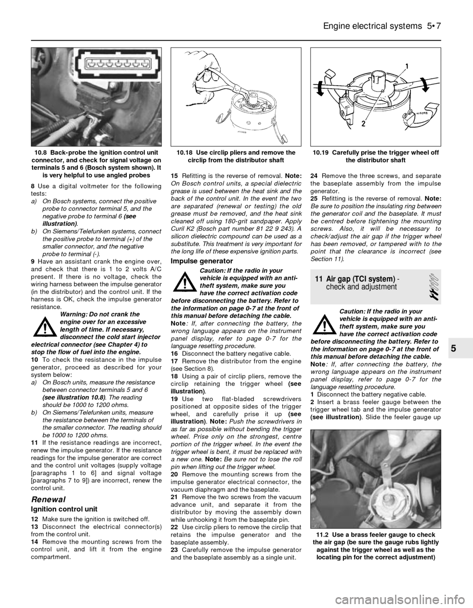
a) On Bosch systems, connect the positive
probe to connector terminal 5, and the
negative probe to terminal 6 (see
illustration).
b) On Siemens/Telefunken systems, connect
the positive probe to terminal (+) of the
smaller connector, and the negative
probe to terminal (-).
9Have an assistant crank the engine over,
and check that there is 1 to 2 volts A/C
present. If there is no voltage, check the
wiring harness between the impulse generator
(in the distributor) and the control unit. If the
harness is OK, check the impulse generator
resistance.
Warning: Do not crank the
engine over for an excessive
length of time. If necessary,
disconnect the cold start injector
electrical connector (see Chapter 4) to
stop the flow of fuel into the engine.
10To check the resistance in the impulse
generator, proceed as described for your
system below:
a) On Bosch units, measure the resistance
between connector terminals 5 and 6
(see illustration 10.8). The reading
should be 1000 to 1200 ohms.
b) On Siemens/Telefunken units, measure
the resistance between the terminals of
the smaller connector. The reading should
be 1000 to 1200 ohms.
11If the resistance readings are incorrect,
renew the impulse generator. If the resistance
readings for the impulse generator are correct
and the control unit voltages (supply voltage
[paragraphs 1 to 6] and signal voltage
[paragraphs 7 to 9]) are incorrect, renew the
control unit.
Renewal
Ignition control unit
12Make sure the ignition is switched off.
13Disconnect the electrical connector(s)
from the control unit.
14Remove the mounting screws from the
control unit, and lift it from the engine
compartment.15Refitting is the reverse of removal. Note:
On Bosch control units, a special dielectric
grease is used between the heat sink and the
back of the control unit. In the event the two
are separated (renewal or testing) the old
grease must be removed, and the heat sink
cleaned off using 180-grit sandpaper. Apply
Curil K2 (Bosch part number 81 22 9 243). A
silicon dielectric compound can be used as a
substitute. This treatment is very important for
the long life of these expensive ignition parts.
Impulse generator
Caution: If the radio in your
vehicle is equipped with an anti-
theft system, make sure you
have the correct activation code
before disconnecting the battery. Refer to
the information on page 0-7 at the front of
this manual before detaching the cable.
Note: If, after connecting the battery, the
wrong language appears on the instrument
panel display, refer to page 0-7 for the
language resetting procedure.
16Disconnect the battery negative cable.
17Remove the distributor from the engine
(see Section 8).
18Using a pair of circlip pliers, remove the
circlip retaining the trigger wheel (see
illustration).
19Use two flat-bladed screwdrivers
positioned at opposite sides of the trigger
wheel, and carefully prise it up (see
illustration). Note: Push the screwdrivers in
as far as possible without bending the trigger
wheel. Prise only on the strongest, centre
portion of the trigger wheel. In the event the
trigger wheel is bent, it must be replaced with
a new one. Note:Be sure not to lose the roll
pin when lifting out the trigger wheel.
20Remove the mounting screws from the
impulse generator electrical connector, the
vacuum diaphragm and the baseplate.
21Remove the two screws from the vacuum
advance unit, and separate it from the
distributor by moving the assembly down
while unhooking it from the baseplate pin.
22Use circlip pliers to remove the circlip that
retains the impulse generator and the
baseplate assembly.
23Carefully remove the impulse generator
and the baseplate assembly as a single unit.24Remove the three screws, and separate
the baseplate assembly from the impulse
generator.
25Refitting is the reverse of removal. Note:
Be sure to position the insulating ring between
the generator coil and the baseplate. It must
be centred before tightening the mounting
screws. Also, it will be necessary to
check/adjust the air gap if the trigger wheel
has been removed, or tampered with to the
point that the clearance is incorrect (see
Section 11).
11 Air gap (TCI system)-
check and adjustment
2
Caution: If the radio in your
vehicle is equipped with an anti-
theft system, make sure you
have the correct activation code
before disconnecting the battery. Refer to
the information on page 0-7 at the front of
this manual before detaching the cable.
Note: If, after connecting the battery, the
wrong language appears on the instrument
panel display, refer to page 0-7 for the
language resetting procedure.
1Disconnect the battery negative cable.
2Insert a brass feeler gauge between the
trigger wheel tab and the impulse generator
(see illustration). Slide the feeler gauge up
Engine electrical systems 5•7
10.19 Carefully prise the trigger wheel off
the distributor shaft10.18 Use circlip pliers and remove the
circlip from the distributor shaft10.8 Back-probe the ignition control unit
connector, and check for signal voltage on
terminals 5 and 6 (Bosch system shown). It
is very helpful to use angled probes
11.2 Use a brass feeler gauge to check
the air gap (be sure the gauge rubs lightly
against the trigger wheel as well as the
locating pin for the correct adjustment)
5
Page 126 of 228
slightly by hand. Release the throttle slowly
until it reaches 0.2 to 0.6 mm from the throttle
stop. There should be continuity.
29Check the resistance between terminals 3
and 18 as the throttle is opened. There should
be continuity when the throttle switch is within
8 to 12 degrees of fully-open. If the readings
are incorrect, adjust the TPS.
30If all the resistance readings are correct
and the TPS is properly adjusted, check for
power (5 volts) at the sensor, and if necessary
trace any wiring circuit problems between the
sensor and ECU (see Chapter 12).
Adjustment
31If the adjustment is not as specified
(paragraphs 28 to 30), loosen the screws on
the TPS, and rotate the sensor into the correct
adjustment. Follow the procedure for
checking the TPS given above, and tighten
the screws when the setting is correct.
32Recheck the TPS once more; if the
readings are correct, reconnect the TPS
harness connector.
Early 535i models with automatic
transmission
Check
33First test the continuity of the TPS. Follow
paragraphs 28 to 30 and check for continuity.
34Next, test the idle position switch (see
illustration). Unplug the electrical connector
in the idle position switch harness, andconnect an ohmmeter to terminals 1 and 2.
There should be continuity. Open the throttle
slightly, and measure the resistance. There
should now be no continuity.
35Check for the correct voltage signals from
the TPS, with the throttle closed and the
ignition on. Probe the back of the TPS
connector with a voltmeter, and check for
voltage at terminal 3 (black wire) and earth.
There should be 5 volts present. Also, probe
terminal 3 (black wire) and terminal 1 (brown
wire). There should be 5 volts present here
also.
36Check for voltage at terminal 2 (yellow
wire) and terminal 1 (brown wire), and slowly
open the throttle. The voltage should increase
steadily from 0.7 volts (throttle closed) to
4.8 volts (throttle fully-open).
Adjustment
37First measure the stabilised voltage. With
the ignition on and the throttle closed,
measure the voltage between terminal 3
(black wire) and terminal 1 (brown wire). It
should be about 5 volts.
38Next, loosen the sensor mounting screws,
and connect the voltmeter to terminal 2
(yellow wire) and terminal 3 (black wire). With
the throttle fully open, rotate the switch until
there is 0.20 to 0.24 volts less than the
stabilised voltage. Note: You will need a
digital voltmeter to measure these small
changes in voltage.
39Recheck the TPS once more; if the
readings are correct, reconnect the TPS
electrical connector. It is a good idea to lock
the TPS screws with paint or thread-locking
compound.
Airflow meter
General description
40The airflow meter is located on the air
intake duct. The airflow meter measures the
amount of air entering the engine. The ECU
uses this information to control fuel delivery. A
large volume of air indicates acceleration,
while a small volume of air indicates
deceleration or idle. Refer to Chapter 4 for all
the diagnostic checks and renewal
procedures for the airflow meter.
Ignition timing sensors
41Ignition timing is electronically-controlled
on Motronic systems, and is not adjustable.
During starting, a crankshaft position sensor
relays the crankshaft position to the ECU, and
an initial baseline ignition point is determined.
Once the engine is running, the ignition point
is continually changing based on the various
input signals to the ECU. Engine speed is
signalled by a speed sensor. Early Motronic
systems have the reference sensor and the
speed sensor mounted on the bellhousing
over the flywheel. Later Motronic systems
have a single sensor (pulse sensor) mounted
over the crankshaft pulley. This sensor
functions as a speed sensor as well as a
position sensor. Refer to Chapter 5 for more
information. Note: Some models are
equipped with a TDC sensor mounted on the
front of the engine. This sensor is strictly for
the BMW service test unit, and it is not part of
the Motronic ignition system.
5 Positive crankcase
ventilation (PCV) system
1The Positive Crankcase Ventilation (PCV)
system (see illustration)reduces
hydrocarbon emissions by scavenging
crankcase vapours. It does this by circulating
blow-by gases and then re-routing them to
the intake manifold by way of the air cleaner.
2This PCV system is a sealed system. The
crankcase blow-by vapours are routed
directly to the air cleaner or air collector with
crankcase pressure behind them. The vapour
is not purged with fresh air on most models or
6•4 Engine management and emission control systems
5.2 PCV hose being removed from the
valve cover5.1 Diagram of the PCV system on the
M20 engine (others similar)4.34 Idle position switch and TPS on early
535i models with automatic transmission
4.28c . . . then check for continuity
between terminals 3 and 18 as the throttle
is opened
Page 127 of 228
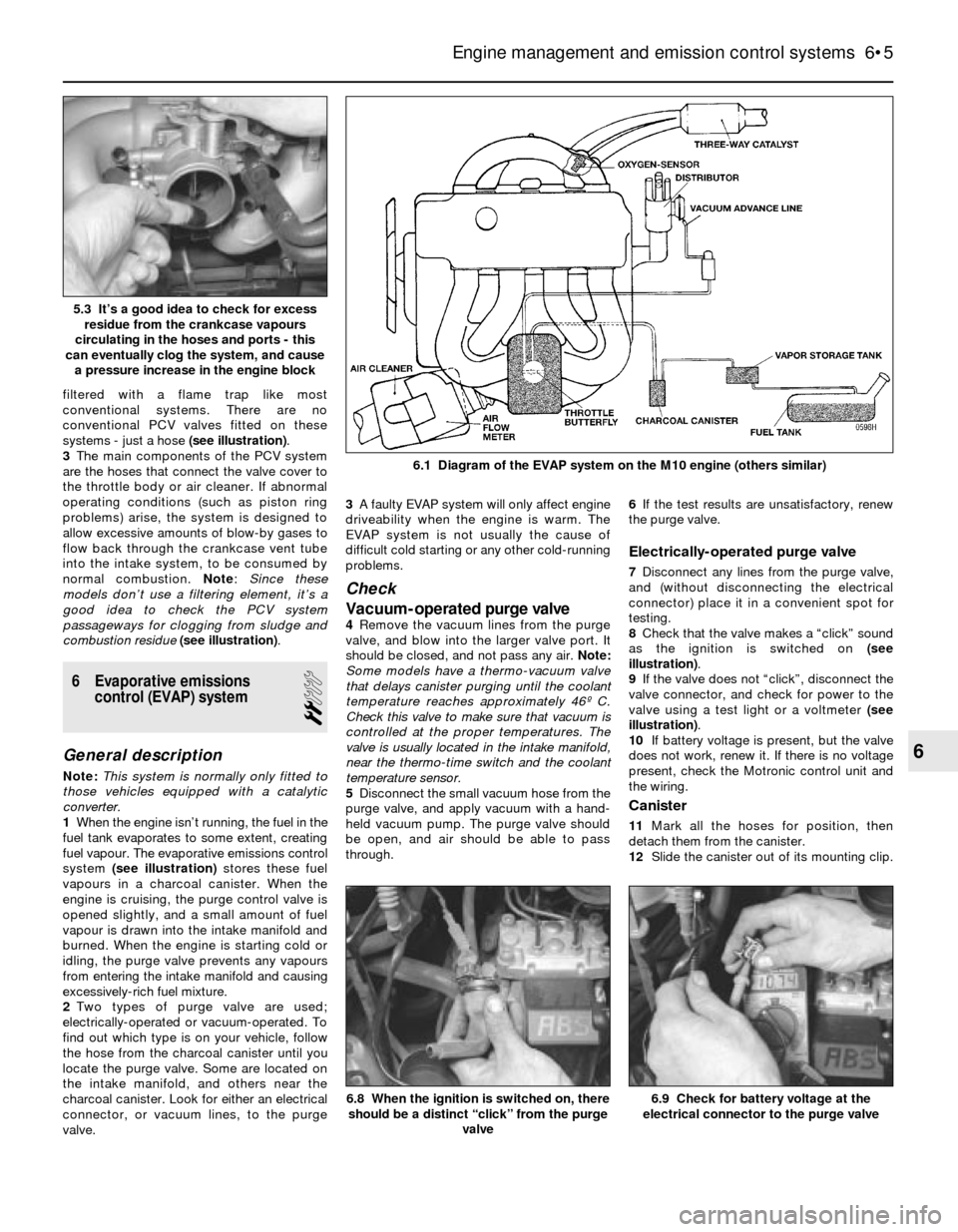
filtered with a flame trap like most
conventional systems. There are no
conventional PCV valves fitted on these
systems - just a hose (see illustration).
3The main components of the PCV system
are the hoses that connect the valve cover to
the throttle body or air cleaner. If abnormal
operating conditions (such as piston ring
problems) arise, the system is designed to
allow excessive amounts of blow-by gases to
flow back through the crankcase vent tube
into the intake system, to be consumed by
normal combustion. Note: Since these
models don’t use a filtering element, it’s a
good idea to check the PCV system
passageways for clogging from sludge and
combustion residue(see illustration).
6 Evaporative emissions
control (EVAP) system
2
General description
Note:This system is normally only fitted to
those vehicles equipped with a catalytic
converter.
1When the engine isn’t running, the fuel in the
fuel tank evaporates to some extent, creating
fuel vapour. The evaporative emissions control
system (see illustration)stores these fuel
vapours in a charcoal canister. When the
engine is cruising, the purge control valve is
opened slightly, and a small amount of fuel
vapour is drawn into the intake manifold and
burned. When the engine is starting cold or
idling, the purge valve prevents any vapours
from entering the intake manifold and causing
excessively-rich fuel mixture.
2Two types of purge valve are used;
electrically-operated or vacuum-operated. To
find out which type is on your vehicle, follow
the hose from the charcoal canister until you
locate the purge valve. Some are located on
the intake manifold, and others near the
charcoal canister. Look for either an electrical
connector, or vacuum lines, to the purge
valve.3A faulty EVAP system will only affect engine
driveability when the engine is warm. The
EVAP system is not usually the cause of
difficult cold starting or any other cold-running
problems.
Check
Vacuum-operated purge valve
4Remove the vacuum lines from the purge
valve, and blow into the larger valve port. It
should be closed, and not pass any air. Note:
Some models have a thermo-vacuum valve
that delays canister purging until the coolant
temperature reaches approximately 46º C.
Check this valve to make sure that vacuum is
controlled at the proper temperatures. The
valve is usually located in the intake manifold,
near the thermo-time switch and the coolant
temperature sensor.
5Disconnect the small vacuum hose from the
purge valve, and apply vacuum with a hand-
held vacuum pump. The purge valve should
be open, and air should be able to pass
through.6If the test results are unsatisfactory, renew
the purge valve.
Electrically-operated purge valve
7Disconnect any lines from the purge valve,
and (without disconnecting the electrical
connector) place it in a convenient spot for
testing.
8Check that the valve makes a “click” sound
as the ignition is switched on (see
illustration).
9If the valve does not “click”, disconnect the
valve connector, and check for power to the
valve using a test light or a voltmeter (see
illustration).
10If battery voltage is present, but the valve
does not work, renew it. If there is no voltage
present, check the Motronic control unit and
the wiring.
Canister
11Mark all the hoses for position, then
detach them from the canister.
12Slide the canister out of its mounting clip.
Engine management and emission control systems 6•5
6.1 Diagram of the EVAP system on the M10 engine (others similar)
6.9 Check for battery voltage at the
electrical connector to the purge valve6.8 When the ignition is switched on, there
should be a distinct “click” from the purge
valve
6
5.3 It’s a good idea to check for excess
residue from the crankcase vapours
circulating in the hoses and ports - this
can eventually clog the system, and cause
a pressure increase in the engine block
Page 129 of 228

9
General
Brake fluid type . . . . . . . . . . . . . . . . . . . . . . . . . . . . . . . . . . . . . . . . . . . . See Chapter 1
Disc brakes
Minimum brake pad thickness . . . . . . . . . . . . . . . . . . . . . . . . . . . . . . . . See Chapter 1
Brake disc minimum permissible thickness (wear limit)*
Front
3-Series
Solid discs . . . . . . . . . . . . . . . . . . . . . . . . . . . . . . . . . . . . . . . . . . 10.7 mm
Ventilated discs . . . . . . . . . . . . . . . . . . . . . . . . . . . . . . . . . . . . . . 20.0 mm
5-Series
Solid discs . . . . . . . . . . . . . . . . . . . . . . . . . . . . . . . . . . . . . . . . . . 10.0 mm
Ventilated discs . . . . . . . . . . . . . . . . . . . . . . . . . . . . . . . . . . . . . . 20.0 mm
Rear . . . . . . . . . . . . . . . . . . . . . . . . . . . . . . . . . . . . . . . . . . . . . . . . . . 8.0 mm
Brake disc minimum thickness after machining
Front
3-Series
Solid discs . . . . . . . . . . . . . . . . . . . . . . . . . . . . . . . . . . . . . . . . . . 11.1 mm
Ventilated discs . . . . . . . . . . . . . . . . . . . . . . . . . . . . . . . . . . . . . . 20.4 mm
5-Series
Solid discs . . . . . . . . . . . . . . . . . . . . . . . . . . . . . . . . . . . . . . . . . . 10.4 mm
Ventilated discs . . . . . . . . . . . . . . . . . . . . . . . . . . . . . . . . . . . . . . 20.4 mm
Rear . . . . . . . . . . . . . . . . . . . . . . . . . . . . . . . . . . . . . . . . . . . . . . . . . . 8.4 mm
Parallelism (difference between any two measurements) . . . . . . . . . . . 0.02 mm
Maximum disc run-out . . . . . . . . . . . . . . . . . . . . . . . . . . . . . . . . . . . . . . 0.2 mm
*Refer to marks cast into the disc (they supersede information printed here)
Brake pedal adjustments
Brake pedal/servo pushrod adjustment (A) (3-Series) . . . . . . . . . . . . . . 125 mm
Brake pedal height (pedal-to-bulkhead distance)
3-Series
Left-hand-drive . . . . . . . . . . . . . . . . . . . . . . . . . . . . . . . . . . . . . . . . 235 mm
Right-hand-drive . . . . . . . . . . . . . . . . . . . . . . . . . . . . . . . . . . . . . . . 273 mm
5-Series . . . . . . . . . . . . . . . . . . . . . . . . . . . . . . . . . . . . . . . . . . . . . . . . 245 mm
Stop-light switch adjustment (dimension A - see text) . . . . . . . . . . . . . . 5.0 mm to 6.0 mm
Handbrake
Handbrake shoe lining minimum thickness . . . . . . . . . . . . . . . . . . . . . . 1.5 mm
Handbrake lever travel . . . . . . . . . . . . . . . . . . . . . . . . . . . . . . . . . . . . . . 5 to 8 clicks
Chapter 9 Braking system
Anti-lock brake system (ABS) - general information . . . . . . . . . . . . . 2
Brake check . . . . . . . . . . . . . . . . . . . . . . . . . . . . . . . . See Chapter 1
Brake disc - inspection, removal and refitting . . . . . . . . . . . . . . . . . 5
Brake fluid level check . . . . . . . . . . . . . . . . . . . . . . . . See Chapter 1
Brake hoses and lines - inspection and renewal . . . . . . . . . . . . . . . . 15
Brake hydraulic system - bleeding . . . . . . . . . . . . . . . . . . . . . . . . . . 16
Brake pedal - adjustment . . . . . . . . . . . . . . . . . . . . . . . . . . . . . . . . . 13
Brake vacuum servo - check, removal and refitting . . . . . . . . . . . . . 8
Disc brake caliper - removal, overhaul and refitting . . . . . . . . . . . . . 4Disc brake pads - renewal . . . . . . . . . . . . . . . . . . . . . . . . . . . . . . . . 3
Drum brake shoes - renewal . . . . . . . . . . . . . . . . . . . . . . . . . . . . . . . 6
General information . . . . . . . . . . . . . . . . . . . . . . . . . . . . . . . . . . . . . . 1
Handbrake assembly - check, removal and refitting . . . . . . . . . . . . 12
Handbrake - adjustment . . . . . . . . . . . . . . . . . . . . . . . . . . . . . . . . . . 11
Handbrake cable(s) - renewal . . . . . . . . . . . . . . . . . . . . . . . . . . . . . . 10
Hydraulic brake servo - description, removal and refitting . . . . . . . . 9
Master cylinder - removal and refitting . . . . . . . . . . . . . . . . . . . . . . . 7
Stop-light switch - check and adjustment . . . . . . . . . . . . . . . . . . . . 14
9•1
Easy,suitable for
novice with little
experienceFairly easy,suitable
for beginner with
some experienceFairly difficult,
suitable for competent
DIY mechanic
Difficult,suitable for
experienced DIY
mechanicVery difficult,
suitable for expert
DIY or professional
Degrees of difficulty
Specifications Contents
Page 138 of 228
expel the air from the master cylinder. A large
Phillips screwdriver can be used to push on
the piston assembly.
11To prevent air from being drawn back into
the master cylinder, the plug must be refitted
and tightened down before releasing the
pressure on the piston assembly.
12Repeat the procedure until brake fluid free
of air bubbles is expelled from the brake line
outlet hole. Repeat the procedure with the
other outlet hole and plug. Be sure to keep the
master cylinder reservoir filled with brake
fluid, to prevent the introduction of air into the
system.
13High pressure is not involved in the bench
bleeding procedure, so the plugs described
above need not be refitted each time the
piston is released, if wished. Instead, before
releasing the piston, simply put your finger
tightly over the hole to keep air from being
drawn back into the master cylinder. Wait
several seconds for brake fluid to be drawn
from the reservoir into the piston bore, then
depress the piston again, removing your
finger as brake fluid is expelled. Be sure to put
your finger back over the hole each time
before releasing the piston, and when the
bleeding procedure is complete for that outlet,
refit the plug and tighten it up before going on
to the other port.
Refitting
14Refit the master cylinder (together with a
new O-ring) over the studs on the brake servo,
and tighten the mounting nuts only finger-tight
at this time.
15Thread the brake line fittings into the
master cylinder. Since the master cylinder is
still a bit loose, it can be moved slightly in
order for the fittings to thread in easily. Do not
strip the threads as the fittings are tightened.
16Tighten the brake fittings securely, and
the mounting nuts to the torque listed in this
Chapter’s Specifications.
17Fill the master cylinder reservoir with fluid,
then bleed the master cylinder (only if the
cylinder has not already been bled) and the
brake system as described in Section 16.
18To bleed the cylinder on the vehicle, have
an assistant pump the brake pedal severaltimes and then hold the pedal to the floor.
Loosen the fitting nut to allow air and fluid to
escape, then tighten the nut. Repeat this
procedure on both fittings until the fluid is
clear of air bubbles. Test the operation of the
brake system carefully before returning the
vehicle to normal service.
8 Brake vacuum servo-
check, removal and refitting
3
Operating check
1Depress the brake pedal several times with
the engine off, until there is no change in the
pedal travel.
2Depress and hold the pedal, then start the
engine. If the pedal goes down slightly,
operation is normal.
Airtightness check
3Start the engine, and turn it off after one or
two minutes. Depress the brake pedal several
times slowly. If the pedal goes down further
the first time but gradually rises after the
second or third depression, the servo is
airtight.
4Depress the brake pedal while the engine is
running, then stop the engine with the pedal
depressed. If there is no change in the pedal
travel after holding the pedal for 30 seconds,
the servo is airtight.
Removal and refitting
5Dismantling the vacuum servo requires
special tools, and cannot be performed by the
home mechanic. If a problem develops, it is
recommended that a new unit be fitted.
6Remove the master cylinder as described in
Section 7.
7Disconnect the vacuum hose from the
brake servo.
8Working in the passenger compartment,
remove the glovebox and lower left-hand trim
panels.
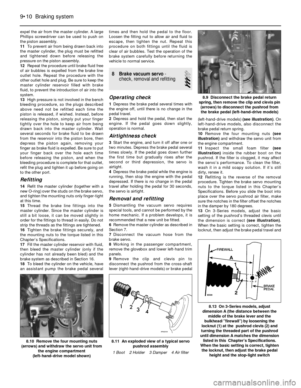
9Remove the clip and clevis pin to
disconnect the pushrod from the cross-shaft
lever (right-hand-drive models) or brake pedal(left-hand-drive models) (see illustration). On
left-hand-drive models, also disconnect the
brake pedal return spring.
10Remove the four mounting nuts (see
illustration)and withdraw the servo unit from
the engine compartment.
11Inspect the small foam filter (see
illustration)inside the rubber boot on the
pushrod. If the filter is clogged, it may affect
the servo’s performance. To clean the filter,
wash it in a mild soapy solution. If it’s still
dirty, renew it.
12Refitting is the reverse of the removal
procedure. Tighten the brake servo mounting
nuts to the torque listed in this Chapter’s
Specifications. Before you slide the boot into
place over the servo pushrod air filter, make
sure the notches in the filter offset the notches
in the damper by 180 degrees.
13On 3-Series models, adjust the basic
setting of the pushrod’s threaded clevis until
the dimension is correct (see illustration).
When the basic setting is correct, tighten the
locknut, then adjust the brake pedal travel and
9•10 Braking system
8.13 On 3-Series models, adjust
dimension A (the distance between the
middle of the brake lever and the
bulkhead/”firewall”) by loosening the
locknut (1) at the pushrod clevis (2) and
turning the threaded part of the pushrod
until dimension A matches the dimension
listed in this Chapter’s Specifications.
When the basic setting is correct, tighten
the locknut, then adjust the brake pedal
height and the stop-light switch
8.11 An exploded view of a typical servo
pushrod assembly
1 Boot 2 Holder 3 Damper 4 Air filter8.10 Remove the four mounting nuts
(arrows) and withdraw the servo unit from
the engine compartment
(left-hand-drive model shown)
8.9 Disconnect the brake pedal return
spring, then remove the clip and clevis pin
(arrows) to disconnect the pushrod from
the brake pedal (left-hand-drive models)
Page 139 of 228
the stop-light switch (see Section 13). Note:
On right-hand-drive models, the brake pedal
in on the right-hand side of the vehicle, and is
connected to the left-hand side by a cross-
shaft. The adjustment is carried out on the
pushrod at the left-hand side, but the
dimension is measured at the pedal on the
right-hand side.
14On 5-Series models, adjust the brake
pedal height and the stop-light switch (see
Section 13).
15Refit the master cylinder (see Section 7)
and attach the vacuum hose.
16Carefully test the operation of the brakes
before returning the vehicle to normal use
9 Hydraulic brake servo-
description, removal and
refitting
3
Warning: Brake fluid is
poisonous. It is also an effective
paint stripper. Refer to the
warning at the start of Section 16.
Description
1On 5-Series E28 (“old-shape”) models, a
hydraulic brake servo system is fitted. The
servo unit, located between the brake pedal
(left-hand-drive) or cross-shaft lever (right-
hand-drive) and the master cylinder, is
operated by hydraulic pressure generated by
the power steering pump. When the engine is
running, the power steering pump supplies
hydraulic pressure to a power flow regulator/
accumulator. The regulator/accumulator
stores and regulates the pressure to the
hydraulic brake servo. When you press the
brake pedal, the pressure in the servo helps
actuate the master cylinder, reducing pedal
effort.
2The hydraulic brake servo cannot be
overhauled; if it fails, a new one must be fitted.
Testing the system requires special tools, so
even fault diagnosis is beyond the scope of
the home mechanic. If the system fails, take it
to a dealer service department or other
qualified garage for repairs.
Removal and refitting
3With the engine off, discharge the hydraulic
accumulator by depressing the brake pedal
20 times or more.
4Remove the master cylinder (see Section 7).
5Clean the area around the return and
supply line fittings, then disconnect them.
Plug the lines, to prevent dirt from entering the
system, and to prevent further fluid loss.
Caution: Even a particle of dirt
can damage the servo, so be
extremely careful to prevent dirt
from entering the system while
the lines are disconnected.
6Working from inside the passenger
compartment, remove the lower left trim
panels above the brake pedal (left-hand-drive
models) or glovebox and trim (right-hand-drive models). On left-hand-drive models, also
disconnect the pedal return spring.
7Prise off the retaining clip, and disconnect
the pushrod from the brake pedal (see
illustration 8.9) or cross-shaft lever.
8Remove the four mounting nuts and
remove the brake servo (see illus-
tration 8.10).
9Refitting is the reverse of removal. Tighten
the hydraulic lines to the torque listed in this
Chapter’s Specifications. Note:Don’t try to
tighten these fittings without a torque wrench.
If they’re loose, they can leak, which can affect
system operation; if they’re tight, they can be
damaged, and they’ll also leak. You’ll need a
crowfoot-type split ring (“brake”) attachment
for your torque wrench to tighten the fittings
properly.
10When you’re done, bleed the brake
hydraulic system (Section 16) and adjust the
brake pedal travel and the stop-light switch
(see Section 13).
10 Handbrake cable(s)- renewal
2
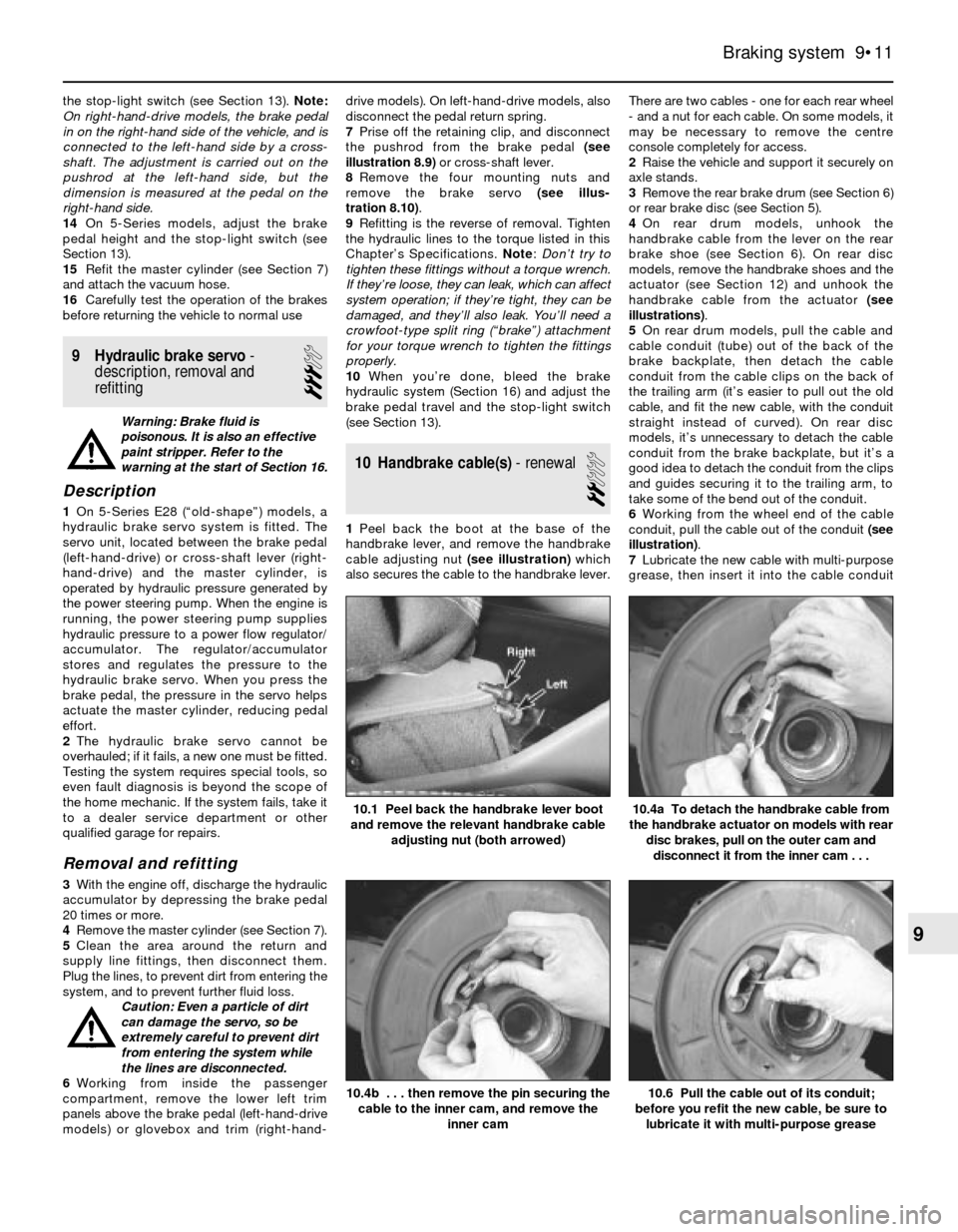
1Peel back the boot at the base of the
handbrake lever, and remove the handbrake
cable adjusting nut (see illustration)which
also secures the cable to the handbrake lever.There are two cables - one for each rear wheel
- and a nut for each cable. On some models, it
may be necessary to remove the centre
console completely for access.
2Raise the vehicle and support it securely on
axle stands.
3Remove the rear brake drum (see Section 6)
or rear brake disc (see Section 5).
4On rear drum models, unhook the
handbrake cable from the lever on the rear
brake shoe (see Section 6). On rear disc
models, remove the handbrake shoes and the
actuator (see Section 12) and unhook the
handbrake cable from the actuator (see
illustrations).
5On rear drum models, pull the cable and
cable conduit (tube) out of the back of the
brake backplate, then detach the cable
conduit from the cable clips on the back of
the trailing arm (it’s easier to pull out the old
cable, and fit the new cable, with the conduit
straight instead of curved). On rear disc
models, it’s unnecessary to detach the cable
conduit from the brake backplate, but it’s a
good idea to detach the conduit from the clips
and guides securing it to the trailing arm, to
take some of the bend out of the conduit.
6Working from the wheel end of the cable
conduit, pull the cable out of the conduit (see
illustration).
7Lubricate the new cable with multi-purpose
grease, then insert it into the cable conduit
Braking system 9•11
10.1 Peel back the handbrake lever boot
and remove the relevant handbrake cable
adjusting nut (both arrowed)
10.6 Pull the cable out of its conduit;
before you refit the new cable, be sure to
lubricate it with multi-purpose grease10.4b . . . then remove the pin securing the
cable to the inner cam, and remove the
inner cam
10.4a To detach the handbrake cable from
the handbrake actuator on models with rear
disc brakes, pull on the outer cam and
disconnect it from the inner cam . . .
9
Page 141 of 228
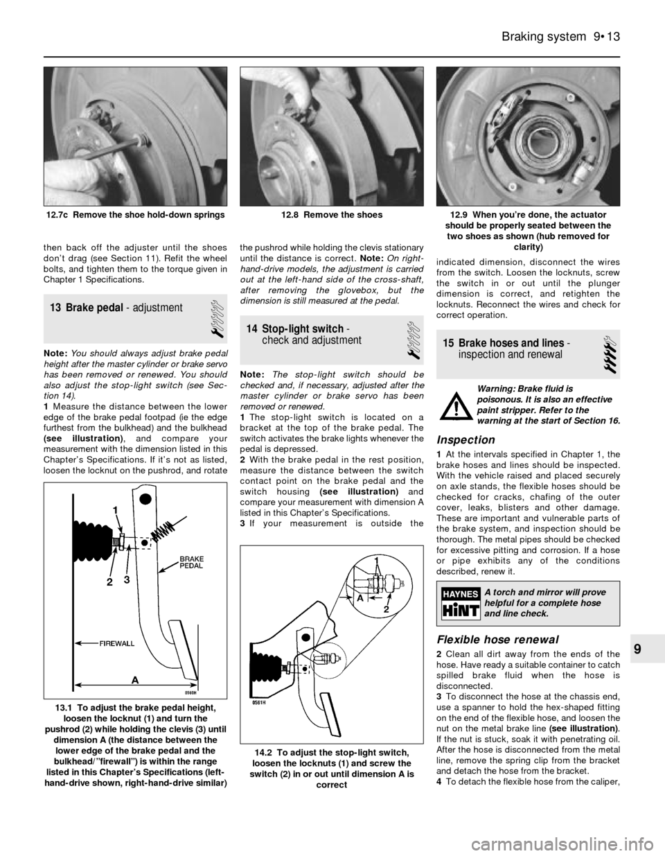
then back off the adjuster until the shoes
don’t drag (see Section 11). Refit the wheel
bolts, and tighten them to the torque given in
Chapter 1 Specifications.
13 Brake pedal- adjustment
1
Note:You should always adjust brake pedal
height after the master cylinder or brake servo
has been removed or renewed. You should
also adjust the stop-light switch (see Sec-
tion 14).
1Measure the distance between the lower
edge of the brake pedal footpad (ie the edge
furthest from the bulkhead) and the bulkhead
(see illustration), and compare your
measurement with the dimension listed in this
Chapter’s Specifications. If it’s not as listed,
loosen the locknut on the pushrod, and rotatethe pushrod while holding the clevis stationary
until the distance is correct. Note:On right-
hand-drive models, the adjustment is carried
out at the left-hand side of the cross-shaft,
after removing the glovebox, but the
dimension is still measured at the pedal.
14 Stop-light switch-
check and adjustment
1
Note:The stop-light switch should be
checked and, if necessary, adjusted after the
master cylinder or brake servo has been
removed or renewed.
1The stop-light switch is located on a
bracket at the top of the brake pedal. The
switch activates the brake lights whenever the
pedal is depressed.
2With the brake pedal in the rest position,
measure the distance between the switch
contact point on the brake pedal and the
switch housing (see illustration)and
compare your measurement with dimension A
listed in this Chapter’s Specifications.
3If your measurement is outside theindicated dimension, disconnect the wires
from the switch. Loosen the locknuts, screw
the switch in or out until the plunger
dimension is correct, and retighten the
locknuts. Reconnect the wires and check for
correct operation.
15 Brake hoses and lines-
inspection and renewal
4
Warning: Brake fluid is
poisonous. It is also an effective
paint stripper. Refer to the
warning at the start of Section 16.
Inspection
1At the intervals specified in Chapter 1, the
brake hoses and lines should be inspected.
With the vehicle raised and placed securely
on axle stands, the flexible hoses should be
checked for cracks, chafing of the outer
cover, leaks, blisters and other damage.
These are important and vulnerable parts of
the brake system, and inspection should be
thorough. The metal pipes should be checked
for excessive pitting and corrosion. If a hose
or pipe exhibits any of the conditions
described, renew it.
Flexible hose renewal
2Clean all dirt away from the ends of the
hose. Have ready a suitable container to catch
spilled brake fluid when the hose is
disconnected.
3To disconnect the hose at the chassis end,
use a spanner to hold the hex-shaped fitting
on the end of the flexible hose, and loosen the
nut on the metal brake line (see illustration).
If the nut is stuck, soak it with penetrating oil.
After the hose is disconnected from the metal
line, remove the spring clip from the bracket
and detach the hose from the bracket.
4To detach the flexible hose from the caliper,
Braking system 9•13
12.9 When you’re done, the actuator
should be properly seated between the
two shoes as shown (hub removed for
clarity)12.8 Remove the shoes12.7c Remove the shoe hold-down springs
14.2 To adjust the stop-light switch,
loosen the locknuts (1) and screw the
switch (2) in or out until dimension A is
correct
13.1 To adjust the brake pedal height,
loosen the locknut (1) and turn the
pushrod (2) while holding the clevis (3) until
dimension A (the distance between the
lower edge of the brake pedal and the
bulkhead/”firewall”) is within the range
listed in this Chapter’s Specifications (left-
hand-drive shown, right-hand-drive similar)
9
A torch and mirror will prove
helpful for a complete hose
and line check.