ECO mode BMW 3 SERIES 1984 E30 Repair Manual
[x] Cancel search | Manufacturer: BMW, Model Year: 1984, Model line: 3 SERIES, Model: BMW 3 SERIES 1984 E30Pages: 228, PDF Size: 7.04 MB
Page 158 of 228
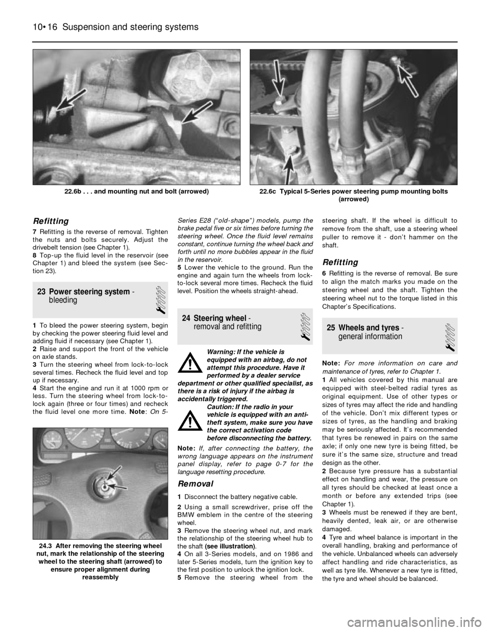
Refitting
7Refitting is the reverse of removal. Tighten
the nuts and bolts securely. Adjust the
drivebelt tension (see Chapter 1).
8Top-up the fluid level in the reservoir (see
Chapter 1) and bleed the system (see Sec-
tion 23).
23 Power steering system-
bleeding
1
1To bleed the power steering system, begin
by checking the power steering fluid level and
adding fluid if necessary (see Chapter 1).
2Raise and support the front of the vehicle
on axle stands.
3Turn the steering wheel from lock-to-lock
several times. Recheck the fluid level and top
up if necessary.
4Start the engine and run it at 1000 rpm or
less. Turn the steering wheel from lock-to-
lock again (three or four times) and recheck
the fluid level one more time. Note:On 5-Series E28 (“old-shape”) models, pump the
brake pedal five or six times before turning the
steering wheel. Once the fluid level remains
constant, continue turning the wheel back and
forth until no more bubbles appear in the fluid
in the reservoir.
5Lower the vehicle to the ground. Run the
engine and again turn the wheels from lock-
to-lock several more times. Recheck the fluid
level. Position the wheels straight-ahead.24 Steering wheel-
removal and refitting
1
Warning: If the vehicle is
equipped with an airbag, do not
attempt this procedure. Have it
performed by a dealer service
department or other qualified specialist, as
there is a risk of injury if the airbag is
accidentally triggered.
Caution: If the radio in your
vehicle is equipped with an anti-
theft system, make sure you have
the correct activation code
before disconnecting the battery.
Note: If, after connecting the battery, the
wrong language appears on the instrument
panel display, refer to page 0-7 for the
language resetting procedure.
Removal
1Disconnect the battery negative cable.
2Using a small screwdriver, prise off the
BMW emblem in the centre of the steering
wheel.
3Remove the steering wheel nut, and mark
the relationship of the steering wheel hub to
the shaft (see illustration).
4On all 3-Series models, and on 1986 and
later 5-Series models, turn the ignition key to
the first position to unlock the ignition lock.
5Remove the steering wheel from thesteering shaft. If the wheel is difficult to
remove from the shaft, use a steering wheel
puller to remove it - don’t hammer on the
shaft.
Refitting
6Refitting is the reverse of removal. Be sure
to align the match marks you made on the
steering wheel and the shaft. Tighten the
steering wheel nut to the torque listed in this
Chapter’s Specifications.
25 Wheels and tyres-
general information
1
Note:For more information on care and
maintenance of tyres, refer to Chapter 1.
1All vehicles covered by this manual are
equipped with steel-belted radial tyres as
original equipment. Use of other types or
sizes of tyres may affect the ride and handling
of the vehicle. Don’t mix different types or
sizes of tyres, as the handling and braking
may be seriously affected. It’s recommended
that tyres be renewed in pairs on the same
axle; if only one new tyre is being fitted, be
sure it’s the same size, structure and tread
design as the other.
2Because tyre pressure has a substantial
effect on handling and wear, the pressure on
all tyres should be checked at least once a
month or before any extended trips (see
Chapter 1).
3Wheels must be renewed if they are bent,
heavily dented, leak air, or are otherwise
damaged.
4Tyre and wheel balance is important in the
overall handling, braking and performance of
the vehicle. Unbalanced wheels can adversely
affect handling and ride characteristics, as
well as tyre life. Whenever a new tyre is fitted,
the tyre and wheel should be balanced.
10•16 Suspension and steering systems
24.3 After removing the steering wheel
nut, mark the relationship of the steering
wheel to the steering shaft (arrowed) to
ensure proper alignment during
reassembly
22.6c Typical 5-Series power steering pump mounting bolts
(arrowed)22.6b . . . and mounting nut and bolt (arrowed)
Page 160 of 228
11
1 General information
These models feature an all-steel welded
construction, where the floorpan and body
components are welded together and
attached to separate front and rear subframe
assemblies. Certain components are
particularly vulnerable to accident damage,
and can be unbolted and repaired or renewed.
Among these parts are the body mouldings,
bumpers, bonnet, doors, tailgate, and all
glass.
Only general body maintenance procedures
and body panel repair procedures within the
scope of the do-it-yourselfer are included in
this Chapter.
2 Bodywork and underframe-
maintenance
1
The general condition of a vehicle’s
bodywork is the one thing that significantly
affects its value. Maintenance is easy, but
needs to be regular. Neglect, particularly after
minor damage, can lead quickly to further
deterioration and costly repair bills. It is
important also to keep watch on those parts
of the vehicle not immediately visible, for
instance the underside, inside all the wheelarches, and the lower part of the engine
compartment.
The basic maintenance routine for the
bodywork is washing - preferably with a lot of
water, from a hose. This will remove all the
loose solids which may have stuck to the
vehicle. It is important to flush these off in
such a way as to prevent grit from scratching
the finish. The wheel arches and underframe
need washing in the same way, to remove any
accumulated mud, which will retain moisture
and tend to encourage rust. Paradoxically
enough, the best time to clean the underframe
and wheel arches is in wet weather, when the
mud is thoroughly wet and soft. In very wet
weather, the underframe is usually cleaned of
large accumulations automatically, and this is
a good time for inspection.
Periodically, except on vehicles with a wax-
based underbody protective coating, it is a
good idea to have the whole of the
underframe of the vehicle steam-cleaned,
engine compartment included, so that a
thorough inspection can be carried out to see
what minor repairs and renovations are
necessary. Steam-cleaning is available at
many garages, and is necessary for the
removal of the accumulation of oily grime,
which sometimes is allowed to become thick
in certain areas. If steam-cleaning facilities are
not available, there are some excellent grease
solvents available which can be brush-
applied; the dirt can then be simply hosed off.
Note that these methods should not be usedon vehicles with wax-based underbody
protective coating, or the coating will be
removed. Such vehicles should be inspected
annually, preferably just prior to Winter, when
the underbody should be washed down, and
any damage to the wax coating repaired.
Ideally, a completely fresh coat should be
applied. It would also be worth considering
the use of such wax-based protection for
injection into door panels, sills, box sections,
etc, as an additional safeguard against rust
damage, where such protection is not
provided by the vehicle manufacturer.
After washing paintwork, wipe off with a
chamois leather to give an unspotted clear
finish. A coat of clear protective wax polish will
give added protection against chemical
pollutants in the air. If the paintwork sheen has
dulled or oxidised, use a cleaner/polisher
combination to restore the brilliance of the
shine. This requires a little effort, but such
dulling is usually caused because regular
washing has been neglected. Care needs to be
taken with metallic paintwork, as special non-
abrasive cleaner/polisher is required to avoid
damage to the finish. Always check that the
door and ventilator opening drain holes and
pipes are completely clear, so that water can
be drained out. Brightwork should be treated in
the same way as paintwork. Windscreens and
windows can be kept clear of the smeary film
which often appears, by the use of proprietary
glass cleaner. Never use any form of wax or
other body or chromium polish on glass.
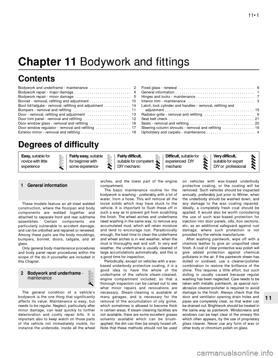
Chapter 11 Bodywork and fittings
Bodywork and underframe - maintenance . . . . . . . . . . . . . . . . . . . . 2
Bodywork repair - major damage . . . . . . . . . . . . . . . . . . . . . . . . . . . 6
Bodywork repair - minor damage . . . . . . . . . . . . . . . . . . . . . . . . . . . 5
Bonnet - removal, refitting and adjustment . . . . . . . . . . . . . . . . . . . . 10
Boot lid/tailgate - removal, refitting and adjustment . . . . . . . . . . . . . 14
Bumpers - removal and refitting . . . . . . . . . . . . . . . . . . . . . . . . . . . . 11
Door - removal, refitting and adjustment . . . . . . . . . . . . . . . . . . . . . 13
Door trim panel - removal and refitting . . . . . . . . . . . . . . . . . . . . . . . 12
Door window glass - removal and refitting . . . . . . . . . . . . . . . . . . . . 16
Door window regulator - removal and refitting . . . . . . . . . . . . . . . . . 17
Exterior mirror - removal and refitting . . . . . . . . . . . . . . . . . . . . . . . . 18Fixed glass - renewal . . . . . . . . . . . . . . . . . . . . . . . . . . . . . . . . . . . . 8
General information . . . . . . . . . . . . . . . . . . . . . . . . . . . . . . . . . . . . . . 1
Hinges and locks - maintenance . . . . . . . . . . . . . . . . . . . . . . . . . . . . 7
Interior trim - maintenance . . . . . . . . . . . . . . . . . . . . . . . . . . . . . . . . 3
Latch, lock cylinder and handles - removal, refitting and
adjustment . . . . . . . . . . . . . . . . . . . . . . . . . . . . . . . . . . . . . . . . . . . 15
Radiator grille - removal and refitting . . . . . . . . . . . . . . . . . . . . . . . . 9
Seat belt check . . . . . . . . . . . . . . . . . . . . . . . . . . . . . . . . . . . . . . . . . 21
Seats - removal and refitting . . . . . . . . . . . . . . . . . . . . . . . . . . . . . . . 20
Steering column shrouds - removal and refitting . . . . . . . . . . . . . . . 19
Upholstery and carpets - maintenance . . . . . . . . . . . . . . . . . . . . . . . 4
11•1
Easy,suitable for
novice with little
experienceFairly easy,suitable
for beginner with
some experienceFairly difficult,
suitable for competent
DIY mechanic
Difficult,suitable for
experienced DIY
mechanicVery difficult,
suitable for expert
DIY or professional
Degrees of difficulty Contents
Page 167 of 228
15 Latch, lock cylinder and
handles- removal, refitting
and adjustment
1
1Remove the trim panel(s) and, on the door,
the plastic shield (see Section 12).
Latch
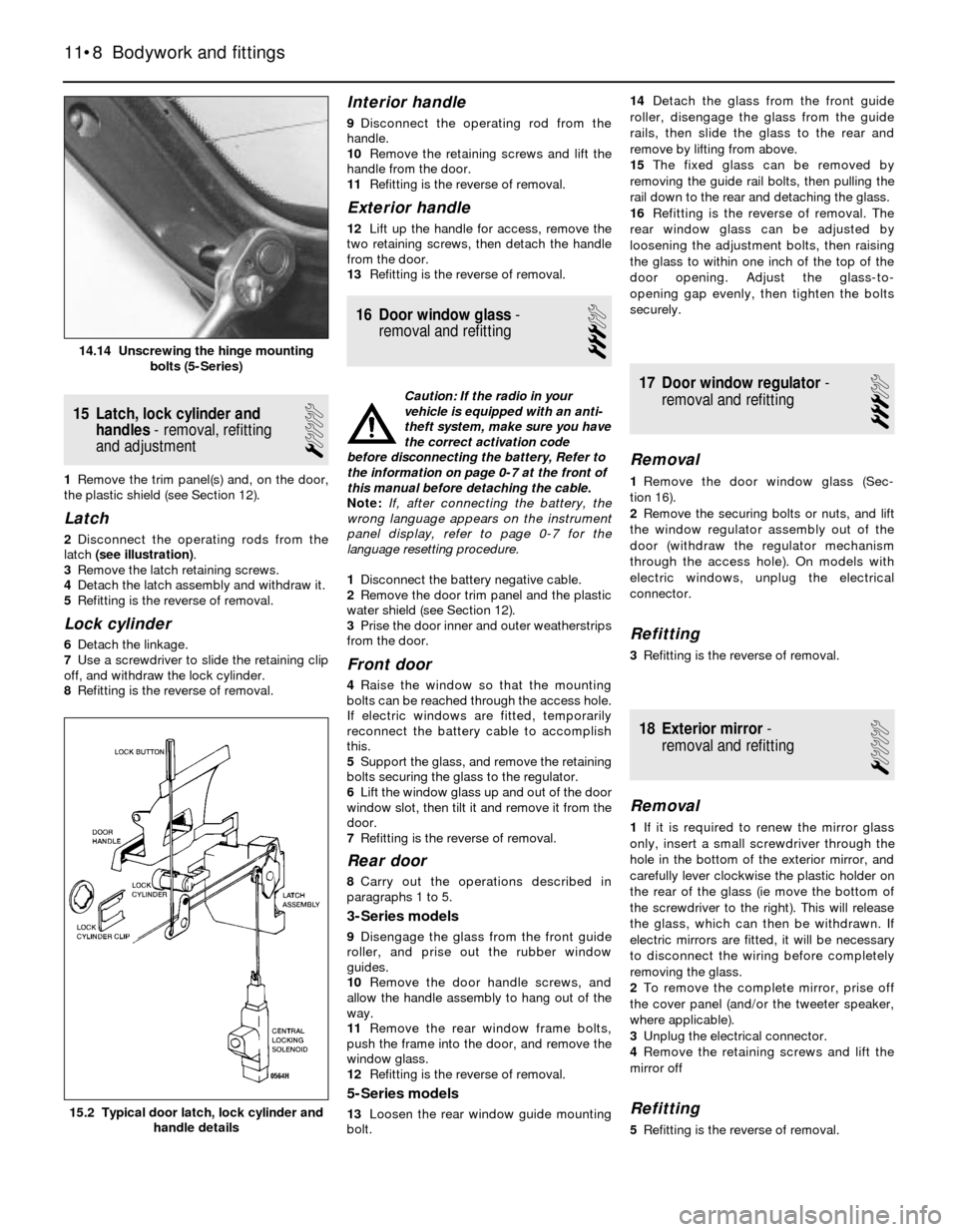
2Disconnect the operating rods from the
latch (see illustration).
3Remove the latch retaining screws.
4Detach the latch assembly and withdraw it.
5Refitting is the reverse of removal.
Lock cylinder
6Detach the linkage.
7Use a screwdriver to slide the retaining clip
off, and withdraw the lock cylinder.
8Refitting is the reverse of removal.
Interior handle
9Disconnect the operating rod from the
handle.
10Remove the retaining screws and lift the
handle from the door.
11Refitting is the reverse of removal.
Exterior handle
12Lift up the handle for access, remove the
two retaining screws, then detach the handle
from the door.
13Refitting is the reverse of removal.
16 Door window glass-
removal and refitting
3
Caution: If the radio in your
vehicle is equipped with an anti-
theft system, make sure you have
the correct activation code
before disconnecting the battery, Refer to
the information on page 0-7 at the front of
this manual before detaching the cable.
Note: If, after connecting the battery, the
wrong language appears on the instrument
panel display, refer to page 0-7 for the
language resetting procedure.
1Disconnect the battery negative cable.
2Remove the door trim panel and the plastic
water shield (see Section 12).
3Prise the door inner and outer weatherstrips
from the door.
Front door
4Raise the window so that the mounting
bolts can be reached through the access hole.
If electric windows are fitted, temporarily
reconnect the battery cable to accomplish
this.
5Support the glass, and remove the retaining
bolts securing the glass to the regulator.
6Lift the window glass up and out of the door
window slot, then tilt it and remove it from the
door.
7Refitting is the reverse of removal.
Rear door
8Carry out the operations described in
paragraphs 1 to 5.
3-Series models
9Disengage the glass from the front guide
roller, and prise out the rubber window
guides.
10Remove the door handle screws, and
allow the handle assembly to hang out of the
way.
11Remove the rear window frame bolts,
push the frame into the door, and remove the
window glass.
12Refitting is the reverse of removal.
5-Series models
13Loosen the rear window guide mounting
bolt.14Detach the glass from the front guide
roller, disengage the glass from the guide
rails, then slide the glass to the rear and
remove by lifting from above.
15The fixed glass can be removed by
removing the guide rail bolts, then pulling the
rail down to the rear and detaching the glass.
16Refitting is the reverse of removal. The
rear window glass can be adjusted by
loosening the adjustment bolts, then raising
the glass to within one inch of the top of the
door opening. Adjust the glass-to-
opening gap evenly, then tighten the bolts
securely.
17 Door window regulator-
removal and refitting
3
Removal
1Remove the door window glass (Sec-
tion 16).
2Remove the securing bolts or nuts, and lift
the window regulator assembly out of the
door (withdraw the regulator mechanism
through the access hole). On models with
electric windows, unplug the electrical
connector.
Refitting
3Refitting is the reverse of removal.
18 Exterior mirror-
removal and refitting
1
Removal
1If it is required to renew the mirror glass
only, insert a small screwdriver through the
hole in the bottom of the exterior mirror, and
carefully lever clockwise the plastic holder on
the rear of the glass (ie move the bottom of
the screwdriver to the right). This will release
the glass, which can then be withdrawn. If
electric mirrors are fitted, it will be necessary
to disconnect the wiring before completely
removing the glass.
2To remove the complete mirror, prise off
the cover panel (and/or the tweeter speaker,
where applicable).
3Unplug the electrical connector.
4Remove the retaining screws and lift the
mirror off
Refitting
5Refitting is the reverse of removal.
11•8 Bodywork and fittings
15.2 Typical door latch, lock cylinder and
handle details
14.14 Unscrewing the hinge mounting
bolts (5-Series)
Page 170 of 228
Finding a short-circuit
One method of finding a short-circuit is to
remove the fuse and connect a test light or
voltmeter in its place. There should be no
voltage present in the circuit. Move the
electrical connectors from side-to-side while
watching the test light. If the bulb goes on,
there is a short to earth somewhere in that
area, probably where the insulation has been
rubbed through. The same test can be
performed on each component in a circuit,
even a switch.
Earth check
Perform a earth check to see whether a
component is properly earthed (passing
current back via the vehicle body). Disconnect
the battery, and connect one lead of a self-
powered test light (often known as a
continuity tester) to a known good earth.
Connect the other lead to the wire or earth
connection being tested. The bulb should
light, indicating a good earth connection. If
not, dismantle the connection, and clean all
relevant parts thoroughly. When re-making
the connection, use serrated (shakeproof)
washers if possible, and tighten all bolts, etc,
securely.
Caution: If the radio in your
vehicle is equipped with an anti-
theft system, make sure you have
the correct activation code
before disconnecting the battery, Refer to
the information on page 0-7 at the front of
this manual before detaching the cable.
Note: If, after connecting the battery, the
wrong language appears on the instrument
panel display, refer to page 0-7 for the
language resetting procedure.
Continuity check
A continuity check determines if there are
any breaks in a circuit - if it is conducting
electricity properly. With the circuit off (no
power in the circuit), a self-powered continuity
tester can be used to check the circuit.
Connect the test leads to both ends of the
circuit, and if the test light comes on, the
circuit is passing current properly. If the light
doesn’t come on, there is a break somewhere
in the circuit. The same procedure can be
used to test a switch, by connecting the
continuity tester to the power-in and power-
out sides of the switch. With the switch turned
on, the test light should come on.
Finding an open-circuit
When diagnosing for possible open-
circuits, it is often difficult to locate them by
sight, because oxidation or terminal
misalignment are hidden by the connectors.
Intermittent problems are often caused by
oxidised or loose connections. Merely
wiggling an electrical connector may correct
the open-circuit condition, albeit temporarily.
Dismantle the connector, and spray with a
water-dispersant aerosol. On simpler
connectors, it may be possible to carefullybend the connector pins inside, to improve
the metal-to-metal contact - don’t damage
the connector in the process, however.
3 Fuses- general information
1
The electrical circuits of the vehicle are
protected by a combination of fuses and
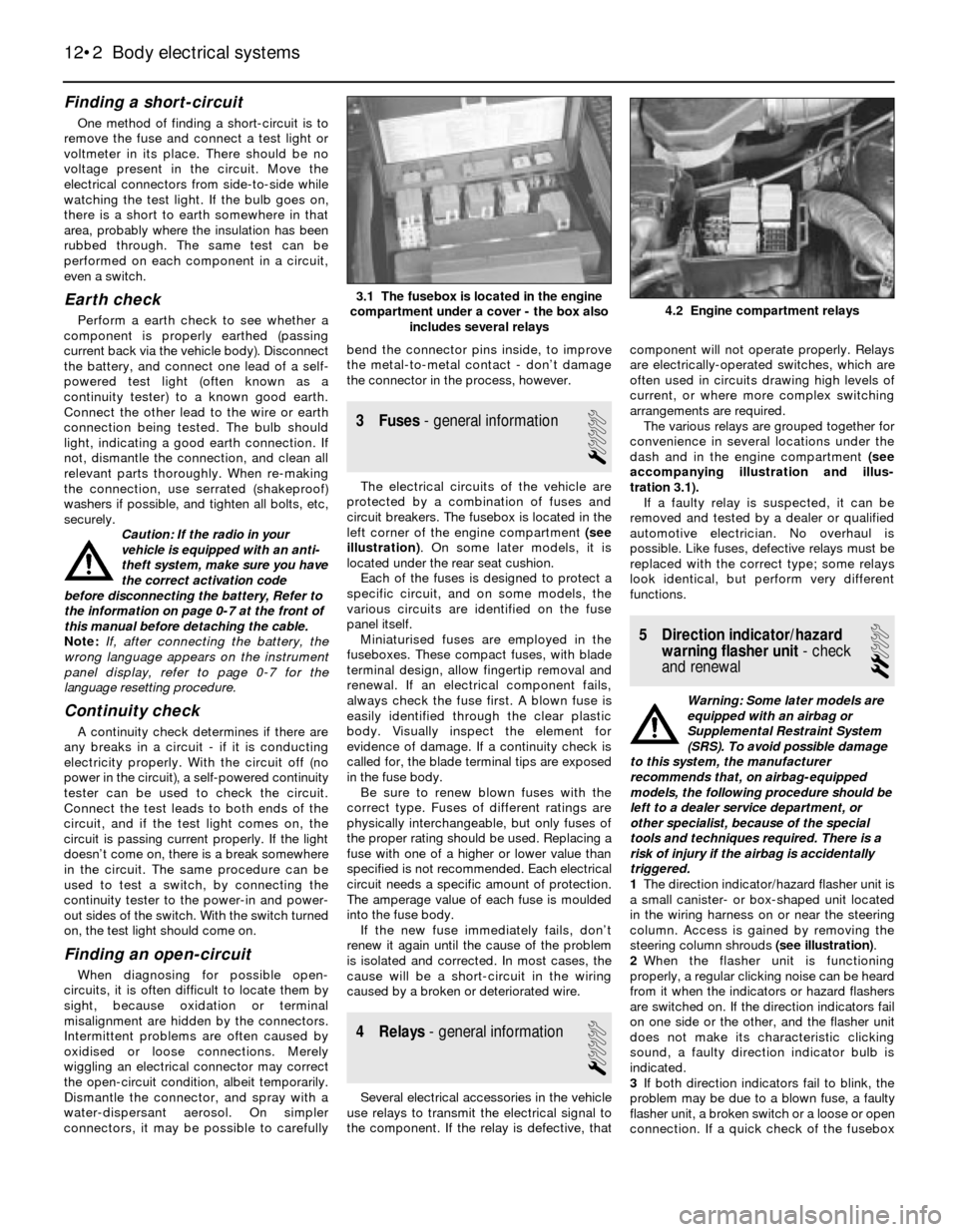
circuit breakers. The fusebox is located in the
left corner of the engine compartment (see
illustration). On some later models, it is
located under the rear seat cushion.
Each of the fuses is designed to protect a
specific circuit, and on some models, the
various circuits are identified on the fuse
panel itself.
Miniaturised fuses are employed in the
fuseboxes. These compact fuses, with blade
terminal design, allow fingertip removal and
renewal. If an electrical component fails,
always check the fuse first. A blown fuse is
easily identified through the clear plastic
body. Visually inspect the element for
evidence of damage. If a continuity check is
called for, the blade terminal tips are exposed
in the fuse body.
Be sure to renew blown fuses with the
correct type. Fuses of different ratings are
physically interchangeable, but only fuses of
the proper rating should be used. Replacing a
fuse with one of a higher or lower value than
specified is not recommended. Each electrical
circuit needs a specific amount of protection.
The amperage value of each fuse is moulded
into the fuse body.
If the new fuse immediately fails, don’t
renew it again until the cause of the problem
is isolated and corrected. In most cases, the
cause will be a short-circuit in the wiring
caused by a broken or deteriorated wire.
4 Relays- general information
1
Several electrical accessories in the vehicle
use relays to transmit the electrical signal to
the component. If the relay is defective, thatcomponent will not operate properly. Relays
are electrically-operated switches, which are
often used in circuits drawing high levels of
current, or where more complex switching
arrangements are required.
The various relays are grouped together for
convenience in several locations under the
dash and in the engine compartment (see
accompanying illustration and illus-
tration 3.1).
If a faulty relay is suspected, it can be
removed and tested by a dealer or qualified
automotive electrician. No overhaul is
possible. Like fuses, defective relays must be
replaced with the correct type; some relays
look identical, but perform very different
functions.
5 Direction indicator/hazard
warning flasher unit- check
and renewal
2
Warning: Some later models are
equipped with an airbag or
Supplemental Restraint System
(SRS). To avoid possible damage
to this system, the manufacturer
recommends that, on airbag-equipped
models, the following procedure should be
left to a dealer service department, or
other specialist, because of the special
tools and techniques required. There is a
risk of injury if the airbag is accidentally
triggered.
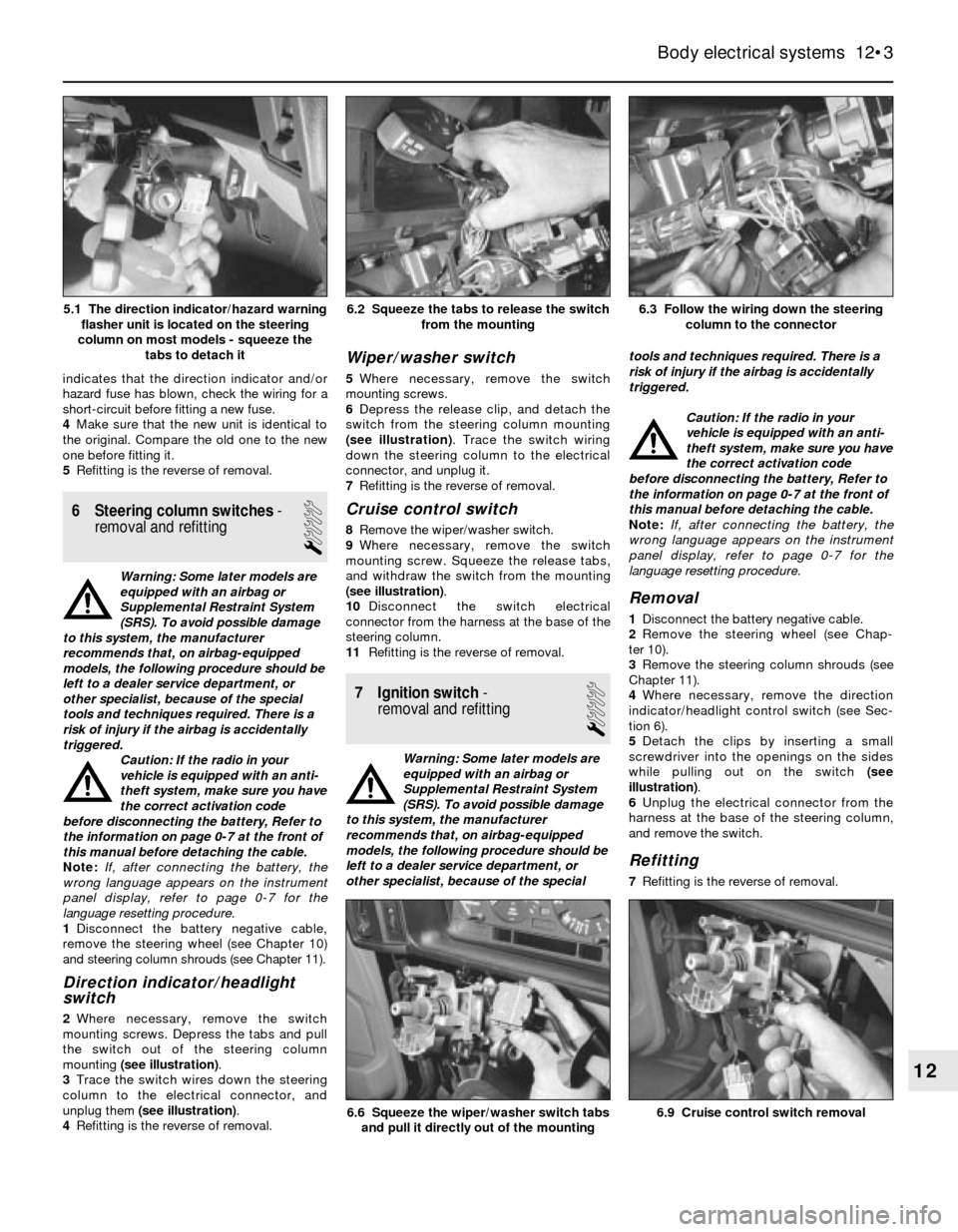
1The direction indicator/hazard flasher unit is
a small canister- or box-shaped unit located
in the wiring harness on or near the steering
column. Access is gained by removing the
steering column shrouds (see illustration).
2When the flasher unit is functioning
properly, a regular clicking noise can be heard
from it when the indicators or hazard flashers
are switched on. If the direction indicators fail
on one side or the other, and the flasher unit
does not make its characteristic clicking
sound, a faulty direction indicator bulb is
indicated.
3If both direction indicators fail to blink, the
problem may be due to a blown fuse, a faulty
flasher unit, a broken switch or a loose or open
connection. If a quick check of the fusebox
12•2 Body electrical systems
4.2 Engine compartment relays3.1 The fusebox is located in the engine
compartment under a cover - the box also
includes several relays
Page 171 of 228
indicates that the direction indicator and/or
hazard fuse has blown, check the wiring for a
short-circuit before fitting a new fuse.
4Make sure that the new unit is identical to
the original. Compare the old one to the new
one before fitting it.
5Refitting is the reverse of removal.
6 Steering column switches-
removal and refitting
1
Warning: Some later models are
equipped with an airbag or
Supplemental Restraint System
(SRS). To avoid possible damage
to this system, the manufacturer
recommends that, on airbag-equipped
models, the following procedure should be
left to a dealer service department, or
other specialist, because of the special
tools and techniques required. There is a
risk of injury if the airbag is accidentally
triggered.
Caution: If the radio in your
vehicle is equipped with an anti-
theft system, make sure you have
the correct activation code
before disconnecting the battery, Refer to
the information on page 0-7 at the front of
this manual before detaching the cable.
Note: If, after connecting the battery, the
wrong language appears on the instrument
panel display, refer to page 0-7 for the
language resetting procedure.
1Disconnect the battery negative cable,
remove the steering wheel (see Chapter 10)
and steering column shrouds (see Chapter 11).
Direction indicator/headlight
switch
2Where necessary, remove the switch
mounting screws. Depress the tabs and pull
the switch out of the steering column
mounting (see illustration).
3Trace the switch wires down the steering
column to the electrical connector, and
unplug them (see illustration).
4Refitting is the reverse of removal.
Wiper/washer switch
5Where necessary, remove the switch
mounting screws.
6Depress the release clip, and detach the
switch from the steering column mounting
(see illustration). Trace the switch wiring
down the steering column to the electrical
connector, and unplug it.
7Refitting is the reverse of removal.
Cruise control switch
8Remove the wiper/washer switch.
9Where necessary, remove the switch
mounting screw. Squeeze the release tabs,
and withdraw the switch from the mounting
(see illustration).
10Disconnect the switch electrical
connector from the harness at the base of the
steering column.
11Refitting is the reverse of removal.
7 Ignition switch-
removal and refitting
1
Warning: Some later models are
equipped with an airbag or
Supplemental Restraint System
(SRS). To avoid possible damage
to this system, the manufacturer
recommends that, on airbag-equipped
models, the following procedure should be
left to a dealer service department, or
other specialist, because of the specialtools and techniques required. There is a
risk of injury if the airbag is accidentally
triggered.
Caution: If the radio in your
vehicle is equipped with an anti-
theft system, make sure you have
the correct activation code
before disconnecting the battery, Refer to
the information on page 0-7 at the front of
this manual before detaching the cable.
Note: If, after connecting the battery, the
wrong language appears on the instrument
panel display, refer to page 0-7 for the
language resetting procedure.
Removal
1Disconnect the battery negative cable.
2Remove the steering wheel (see Chap-
ter 10).
3Remove the steering column shrouds (see
Chapter 11).
4Where necessary, remove the direction
indicator/headlight control switch (see Sec-
tion 6).
5Detach the clips by inserting a small
screwdriver into the openings on the sides
while pulling out on the switch (see
illustration).
6Unplug the electrical connector from the
harness at the base of the steering column,
and remove the switch.
Refitting
7Refitting is the reverse of removal.
Body electrical systems 12•3
6.3 Follow the wiring down the steering
column to the connector6.2 Squeeze the tabs to release the switch
from the mounting
6.9 Cruise control switch removal6.6 Squeeze the wiper/washer switch tabs
and pull it directly out of the mounting
12
5.1 The direction indicator/hazard warning
flasher unit is located on the steering
column on most models - squeeze the
tabs to detach it
Page 175 of 228
16 Windscreen/tailgate wiper
motor- removal and refitting
2
Caution: If the radio in your
vehicle is equipped with an anti-
theft system, make sure you have
the correct activation code
before disconnecting the battery, Refer to
the information on page 0-7 at the front of
this manual before detaching the cable.
Note: If, after connecting the battery, the
wrong language appears on the instrument
panel display, refer to page 0-7 for the
language resetting procedure.
1Disconnect the battery negative cable.
Windscreen wiper motor
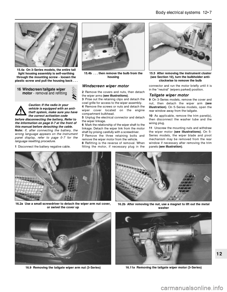
2Remove the covers and nuts, then detach
the wiper arms (see illustrations).
3Prise out the retaining clips and detach the
cowl grille for access to the wiper assembly.
4Remove the screws or nuts and detach the
wiper cover located on the engine
compartment bulkhead.
5Unplug the electrical connector and detach
the wiper linkage.
6Mark the relationship of the wiper shaft to the
linkage. Detach the wiper link from the motor
shaft by prising carefully with a screwdriver.
7Remove the three retaining bolts and
remove the wiper motor from the vehicle.
8Refitting is the reverse of removal. When
fitting the motor, if necessary plug in theconnector and run the motor briefly until it is
in the “neutral” (wipers parked) position.Tailgate wiper motor
9On 3-Series models, remove the cover and
nut, then detach the wiper arm (see
illustration). On 5-Series models, open the
rear window away from the tailgate.
10As applicable, remove the trim panel(s),
then disconnect the washer tube and the
wiring plug.
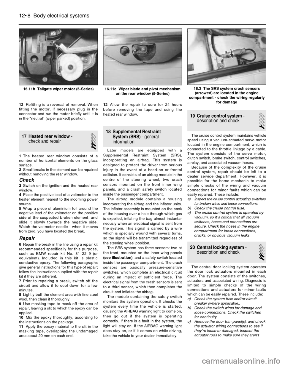
11Unscrew the mounting nuts and withdraw
the wiper motor (see illustrations). On 5-
Series models, the wiper blade and pivot
mechanism may be removed from the rear
window if necessary after removing the trim
panels (see illustration).
Body electrical systems 12•7
15.5 After removing the instrument cluster
(see Section 10), turn the bulbholder anti-
clockwise to remove the bulb15.4b . . . then remove the bulb from the
housing15.4a On 3-Series models, the entire tail
light housing assembly is self-earthing
through the mounting screw - loosen the
plastic screw and pull the housing back . . .
16.11a Removing the tailgate wiper motor (3-Series)
16.2b After removing the nut, use a magnet to lift out the metal
washer16.2a Use a small screwdriver to detach the wiper arm nut cover,
or swivel the cover up
16.9 Removing the tailgate wiper arm nut (3-Series)
12
Page 176 of 228
12Refitting is a reversal of removal. When
fitting the motor, if necessary plug in the
connector and run the motor briefly until it is
in the “neutral” (wiper parked) position.
17 Heated rear window-
check and repair
2
1The heated rear window consists of a
number of horizontal elements on the glass
surface.
2Small breaks in the element can be repaired
without removing the rear window.
Check
3Switch on the ignition and the heated rear
window.
4Place the positive lead of a voltmeter to the
heater element nearest to the incoming power
source.
5Wrap a piece of aluminium foil around the
negative lead of the voltmeter on the positive
side of the suspected broken element, and
slide it slowly towards the negative side.
Watch the voltmeter needle - when it moves
from zero, you have located the break.
Repair
6Repair the break in the line using a repair kit
recommended specifically for this purpose,
such as BMW repair kit No. 81 22 9 (or
equivalent). Included in this kit is plastic
conductive epoxy. The following paragraphs
give general instructions for this type of repair;
follow the instructions supplied with the repair
kit if they are different.
7Prior to repairing a break, switch off the
circuit and allow it to cool down for a few
minutes.
8Lightly buff the element area with fine steel
wool, then clean it thoroughly.
9Use masking tape to mask off the area of
repair, leaving a slit to which the epoxy can be
applied.
10Mix the epoxy thoroughly, according to
the instructions on the package.
11Apply the epoxy material to the slit in the
masking tape, overlapping the undamaged
area about 20 mm on each end.12Allow the repair to cure for 24 hours
before removing the tape and using the
heated rear window.
18 Supplemental Restraint
System (SRS)- general
information
Later models are equipped with a
Supplemental Restraint System (SRS),
incorporating an airbag. This system is
designed to protect the driver from serious
injury in the event of a head-on or frontal
collision. It consists of an airbag module in the
centre of the steering wheel, two crash
sensors mounted on the front inner wing
panels, and a crash safety switch located
inside the passenger compartment.
The airbag module contains a housing
incorporating the airbag and the inflator units.
The inflator assembly is mounted on the back
of the housing over a hole through which gas
is expelled, inflating the bag almost instanta-
neously when an electrical signal is sent from
the system. This signal is carried by a wire
which is specially wound with several turns,
so the signal will be transmitted regardless of
the steering wheel position.
The SRS system has three sensors: two at
the front, mounted on the inner wing panels
(see illustration), and a safety switch located
inside the passenger compartment. The crash
sensors are basically pressure-sensitive
switches, which complete an electrical circuit
during an impact of sufficient force. The
electrical signal from the crash sensors is sent
to a third sensor, which then completes the
circuit and inflates the airbag.
The module containing the safety switch
monitors the system operation. It checks the
system every time the vehicle is started,
causing the AIRBAG warning light to come on,
then go out if the system is operating
correctly. If there is a fault in the system, the
light will stay on. If the AIRBAG warning light
does stay on, or if it comes on while driving,
take the vehicle to your dealer immediately.
19 Cruise control system-
description and check
1
The cruise control system maintains vehicle
speed using a vacuum-actuated servo motor
located in the engine compartment, which is
connected to the throttle linkage by a cable.
The system consists of the servo motor,
clutch switch, brake switch, control switches,
a relay, and associated vacuum hoses.
Because of the complexity of the cruise
control system, repair should be left to a
dealer service department. However, it is
possible for the home mechanic to make
simple checks of the wiring and vacuum
connections for minor faults which can be
easily repaired. These include:
a) Inspect the cruise control actuating switches
for broken wires and loose connections.
b) Check the cruise control fuse.
c) The cruise control system is operated by
vacuum, so it’s critical that all vacuum
switches, hoses and connections are
secure. Check the hoses in the engine
compartment for loose connections,
cracks, or obvious vacuum leaks.
20 Central locking system-
description and check
2
The central door locking system operates
the door lock actuators mounted in each
door. The system consists of the switches,
actuators and associated wiring. Diagnosis is
limited to simple checks of the wiring
connections and actuators for minor faults
which can be easily repaired. These include:
a) Check the system fuse and/or circuit
breaker (where applicable).
b) Check the switch wires for damage and
loose connections. Check the switches
for continuity.
c) Remove the door trim panel(s), and check
the actuator wiring connections to see if
they’re loose or damaged. Inspect the
actuator rods to make sure they aren’t
12•8 Body electrical systems
18.3 The SRS system crash sensors
(arrowed) are located in the engine
compartment - check the wiring regularly
for damage16.11b Tailgate wiper motor (5-Series)16.11c Wiper blade and pivot mechanism
on the rear window (5-Series)
Page 205 of 228
REF•4MOT Test Checks
MExamine the handbrake mechanism,
checking for frayed or broken cables,
excessive corrosion, or wear or insecurity of
the linkage. Check that the mechanism works
on each relevant wheel, and releases fully,
without binding.
MIt is not possible to test brake efficiency
without special equipment, but a road test can
be carried out later to check that the vehicle
pulls up in a straight line.
Fuel and exhaust systems
MInspect the fuel tank (including the filler
cap), fuel pipes, hoses and unions. All
components must be secure and free from
leaks.
MExamine the exhaust system over its entire
length, checking for any damaged, broken or
missing mountings, security of the retaining
clamps and rust or corrosion.
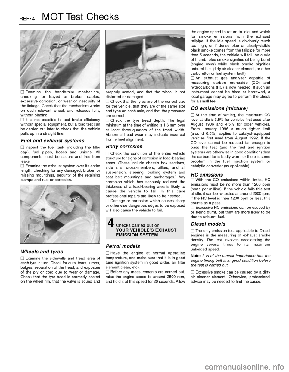
Wheels and tyres
MExamine the sidewalls and tread area of
each tyre in turn. Check for cuts, tears, lumps,
bulges, separation of the tread, and exposure
of the ply or cord due to wear or damage.
Check that the tyre bead is correctly seated
on the wheel rim, that the valve is sound andproperly seated, and that the wheel is not
distorted or damaged.
MCheck that the tyres are of the correct size
for the vehicle, that they are of the same size
and type on each axle, and that the pressures
are correct.
MCheck the tyre tread depth. The legal
minimum at the time of writing is 1.6 mm over
at least three-quarters of the tread width.
Abnormal tread wear may indicate incorrect
front wheel alignment.
Body corrosion
MCheck the condition of the entire vehicle
structure for signs of corrosion in load-bearing
areas. (These include chassis box sections,
side sills, cross-members, pillars, and all
suspension, steering, braking system and
seat belt mountings and anchorages.) Any
corrosion which has seriously reduced the
thickness of a load-bearing area is likely to
cause the vehicle to fail. In this case
professional repairs are likely to be needed.
MDamage or corrosion which causes sharp
or otherwise dangerous edges to be exposed
will also cause the vehicle to fail.
Petrol models
MHave the engine at normal operating
temperature, and make sure that it is in good
tune (ignition system in good order, air filter
element clean, etc).
MBefore any measurements are carried out,
raise the engine speed to around 2500 rpm,
and hold it at this speed for 20 seconds. Allowthe engine speed to return to idle, and watch
for smoke emissions from the exhaust
tailpipe. If the idle speed is obviously much
too high, or if dense blue or clearly-visible
black smoke comes from the tailpipe for more
than 5 seconds, the vehicle will fail. As a rule
of thumb, blue smoke signifies oil being burnt
(engine wear) while black smoke signifies
unburnt fuel (dirty air cleaner element, or other
carburettor or fuel system fault).
MAn exhaust gas analyser capable of
measuring carbon monoxide (CO) and
hydrocarbons (HC) is now needed. If such an
instrument cannot be hired or borrowed, a
local garage may agree to perform the check
for a small fee.
CO emissions (mixture)
MAt the time of writing, the maximum CO
level at idle is 3.5% for vehicles first used after
August 1986 and 4.5% for older vehicles.
From January 1996 a much tighter limit
(around 0.5%) applies to catalyst-equipped
vehicles first used from August 1992. If the
CO level cannot be reduced far enough to
pass the test (and the fuel and ignition
systems are otherwise in good condition) then
the carburettor is badly worn, or there is some
problem in the fuel injection system or
catalytic converter (as applicable).
HC emissionsMWith the CO emissions within limits, HC
emissions must be no more than 1200 ppm
(parts per million). If the vehicle fails this test
at idle, it can be re-tested at around 2000 rpm;
if the HC level is then 1200 ppm or less, this
counts as a pass.
MExcessive HC emissions can be caused by
oil being burnt, but they are more likely to be
due to unburnt fuel.
Diesel models
MThe only emission test applicable to Diesel
engines is the measuring of exhaust smoke
density. The test involves accelerating the
engine several times to its maximum
unloaded speed.
Note: It is of the utmost importance that the
engine timing belt is in good condition before
the test is carried out.
M
Excessive smoke can be caused by a dirty
air cleaner element. Otherwise, professional
advice may be needed to find the cause.
4Checks carried out on
YOUR VEHICLE’S EXHAUST
EMISSION SYSTEM
Page 206 of 228
Introduction
A selection of good tools is a fundamental
requirement for anyone contemplating the
maintenance and repair of a motor vehicle.
For the owner who does not possess any,
their purchase will prove a considerable
expense, offsetting some of the savings made
by doing-it-yourself. However, provided that
the tools purchased meet the relevant national
safety standards and are of good quality, they
will last for many years and prove an
extremely worthwhile investment.
To help the average owner to decide which
tools are needed to carry out the various tasks
detailed in this manual, we have compiled
three lists of tools under the following
headings: Maintenance and minor repair,
Repair and overhaul, and Special. Newcomers
to practical mechanics should start off with
the Maintenance and minor repairtool kit, and
confine themselves to the simpler jobs around
the vehicle. Then, as confidence and
experience grow, more difficult tasks can be
undertaken, with extra tools being purchased
as, and when, they are needed. In this way, a
Maintenance and minor repairtool kit can be
built up into a Repair and overhaultool kit over
a considerable period of time, without any
major cash outlays. The experienced do-it-
yourselfer will have a tool kit good enough for
most repair and overhaul procedures, and will
add tools from the Specialcategory when it is
felt that the expense is justified by the amount
of use to which these tools will be put.
Maintenance and minor repair
tool kit
The tools given in this list should be
considered as a minimum requirement if
routine maintenance, servicing and minor
repair operations are to be undertaken. We
recommend the purchase of combination
spanners (ring one end, open-ended the
other); although more expensive than open-
ended ones, they do give the advantages of
both types of spanner.
MCombination spanners:
Metric - 8, 9, 10, 11, 12, 13, 14, 15, 16, 17,
19, 21, 22, 24 & 26 mm
MAdjustable spanner - 35 mm jaw (approx)
MTransmission drain plug key (Allen type)
MSet of feeler gauges
MSpark plug spanner (with rubber insert)
MSpark plug gap adjustment tool
MBrake bleed nipple spanner
MScrewdrivers:
Flat blade - approx 100 mm long x 6 mm dia
Cross blade - approx 100 mm long x
6 mm dia
MCombination pliers
MHacksaw (junior)
MTyre pump
MTyre pressure gauge
MOil can
MOil filter removal tool
MFine emery cloth
MWire brush (small)
MFunnel (medium size)
Repair and overhaul tool kit
These tools are virtually essential for
anyone undertaking any major repairs to a
motor vehicle, and are additional to those
given in the Maintenance and minor repairlist.
Included in this list is a comprehensive set of
sockets. Although these are expensive, they
will be found invaluable as they are so
versatile - particularly if various drives are
included in the set. We recommend the half-
inch square-drive type, as this can be used
with most proprietary torque wrenches. If you
cannot afford a socket set, even bought
piecemeal, then inexpensive tubular box
spanners are a useful alternative.
The tools in this list will occasionally need
to be supplemented by tools from the Special
list:
MSockets (or box spanners) to cover range in
previous list
MReversible ratchet drive (for use with
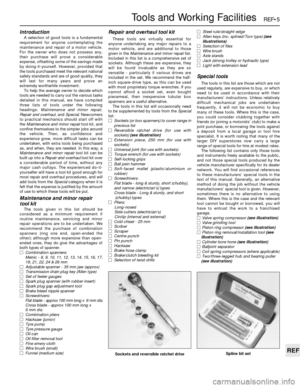
sockets) (see illustration)
MExtension piece, 250 mm (for use with
sockets)
MUniversal joint (for use with sockets)
MTorque wrench (for use with sockets)
MSelf-locking grips
MBall pein hammer
MSoft-faced mallet (plastic/aluminium or
rubber)
MScrewdrivers:
Flat blade - long & sturdy, short (chubby),
and narrow (electrician’s) types
Cross blade - Long & sturdy, and short
(chubby) types
MPliers:
Long-nosed
Side cutters (electrician’s)
Circlip (internal and external)
MCold chisel - 25 mm
MScriber
MScraper
MCentre-punch
MPin punch
MHacksaw
MBrake hose clamp
MBrake/clutch bleeding kit
MSelection of twist drillsMSteel rule/straight-edge
MAllen keys (inc. splined/Torx type) (see
illustrations)
MSelection of files
MWire brush
MAxle stands
MJack (strong trolley or hydraulic type)
MLight with extension lead
Special tools
The tools in this list are those which are not
used regularly, are expensive to buy, or which
need to be used in accordance with their
manufacturers’ instructions. Unless relatively
difficult mechanical jobs are undertaken
frequently, it will not be economic to buy
many of these tools. Where this is the case,
you could consider clubbing together with
friends (or joining a motorists’ club) to make a
joint purchase, or borrowing the tools against
a deposit from a local garage or tool hire
specialist. It is worth noting that many of the
larger DIY superstores now carry a large
range of special tools for hire at modest rates.
The following list contains only those tools
and instruments freely available to the public,
and not those special tools produced by the
vehicle manufacturer specifically for its dealer
network. You will find occasional references
to these manufacturers’ special tools in the
text of this manual. Generally, an alternative
method of doing the job without the vehicle
manufacturers’ special tool is given. However,
sometimes there is no alternative to using
them. Where this is the case and the relevant
tool cannot be bought or borrowed, you will
have to entrust the work to a franchised
garage.
MValve spring compressor (see illustration)
MValve grinding tool
MPiston ring compressor (see illustration)
MPiston ring removal/installation tool (see
illustration)
MCylinder bore hone (see illustration)
MBalljoint separator
MCoil spring compressors (where applicable)
MTwo/three-legged hub and bearing puller
(see illustration)
REF•5
REF
Tools and Working Facilities
Sockets and reversible ratchet driveSpline bit set
Page 212 of 228
REF•11
REF
Fault Finding
Engine misses at idle speed
m mSpark plugs worn or incorrectly-gapped (Chapter 1).
m mFaulty spark plug HT leads (Chapter 1).
m mVacuum leaks (Chapter 1).
m mIncorrect ignition timing (Chapter 5).
m mUneven or low compression (Chapter 2).
m mFaulty charcoal canister, where fitted (Chapter 6).
Engine misses throughout driving speed range
m
mFuel filter clogged and/or impurities in the fuel system (Chapter 1).
m mLow fuel output at the injectors, or partially-blocked carburettor
jets (Chapter 4).
m mFaulty or incorrectly-gapped spark plugs (Chapter 1).
m mIncorrect ignition timing (Chapter 5).
m mCracked distributor cap, disconnected distributor HT leads, or
damaged distributor components (Chapter 1).
m mFaulty spark plug HT leads (Chapter 1).
m mFaulty emission system components (Chapter 6).
m mLow or uneven cylinder compression pressures (Chapter 2).
m mWeak or faulty ignition system (Chapter 5).
m mVacuum leak in fuel injection system, intake manifold or vacuum
hoses (Chapter 4).
Engine misfires on acceleration
m mSpark plugs fouled (Chapter 1).
m mFuel injection system or carburettor malfunctioning (Chapter 4).
m mFuel filter clogged (Chapters 1 and 4).
m mIncorrect ignition timing (Chapter 5).
m mIntake manifold air leak (Chapter 4).
Engine surges while holding accelerator steady
m
mIntake air leak (Chapter 4).
m mFuel pump faulty (Chapter 4).
m mLoose fuel injector harness connections (Chapters 4 and 6).
m mDefective ECU (Chapter 5).
Engine lacks power
m
mIncorrect ignition timing (Chapter 5).
m mExcessive play in distributor shaft (Chapter 5).
m mWorn rotor, distributor cap or HT leads (Chapters 1 and 5).
m mFaulty or incorrectly-gapped spark plugs (Chapter 1).
m mFuel injection system or carburettor malfunctioning (Chapter 4).
m mFaulty coil (Chapter 5).
m mBrakes binding (Chapter 1).
m mAutomatic transmission fluid level incorrect (Chapter 1).
m mClutch slipping (Chapter 8).
m mFuel filter clogged and/or impurities in the fuel system (Chapter 1).
m mEmission control system not functioning properly (Chapter 6).
m mLow or uneven cylinder compression pressures (Chapter 2).
Engine stalls
m
mIdle speed incorrect (Chapter 1).
m mFuel filter clogged and/or water and impurities in the fuel system
(Chapter 1).
m mDistributor components damp or damaged (Chapter 5).
m mFaulty emissions system components (Chapter 6).
m mFaulty or incorrectly-gapped spark plugs (Chapter 1).
m mFaulty spark plug HT leads (Chapter 1).
m mVacuum leak in the fuel injection system, intake manifold or
vacuum hoses (Chapter 4).
Engine backfires
m mEmissions system not functioning properly (Chapter 6).
m mIgnition timing incorrect (Chapter 5).
m mFaulty secondary ignition system (cracked spark plug insulator,
faulty plug HT leads, distributor cap and/or rotor) (Chapters 1 and 5).
m mFuel injection system or carburettor malfunctioning (Chapter 4).
m mVacuum leak at fuel injector(s), intake manifold or vacuum hoses
(Chapter 4).
m mValve clearances incorrect (Chapter 1), or valve(s) sticking or
damaged (Chapter 2).
Pinking or knocking engine sounds when
accelerating or driving uphill
m mIncorrect grade of fuel.
m mIgnition timing incorrect (Chapter 5).
m mFuel injection system or carburettor in need of adjustment (Chap-
ter 4).
m mDamaged spark plugs or HT leads, or incorrect type fitted (Chapter 1).
m mWorn or damaged distributor components (Chapter 5).
m mFaulty emission system (Chapter 6).
m mVacuum leak (Chapter 4).
Engine runs with oil pressure light on
Caution: Stop the engine immediately if the oil
pressure light comes on and establish the cause.
Running the engine while the oil pressure is low can
cause severe damage.
m mLow oil level (Chapter 1).
m mIdle speed too low (Chapter 1).
m mShort-circuit in wiring (Chapter 12).
m mFaulty oil pressure sender unit (Chapter 2).
m mWorn engine bearings and/or oil pump (Chapter 2).
Engine runs-on after switching off
m
mIdle speed too high (Chapter 1).
m mExcessive engine operating temperature (Chapter 3).
m mIncorrect fuel octane grade.
m mSpark plugs defective or incorrect grade (Chapter 1).
Engine electrical system
Battery will not hold charge
m
mAlternator drivebelt defective or not adjusted properly (Chapter 1).
m mElectrolyte level low (Chapter 1).
m mBattery terminals loose or corroded (Chapter 1).
m mAlternator not charging properly (Chapter 5).
m mLoose, broken or faulty wiring in the charging circuit (Chapter 5).
m mShort in vehicle wiring (Chapters 5 and 12).
m mInternally-defective battery (Chapters 1 and 5).
m mIgnition (no-charge) warning light bulb blown - on some early
models (Chapter 5)
Ignition (no-charge) warning light fails to go out
m mFaulty alternator or charging circuit (Chapter 5).
m mAlternator drivebelt defective or out of adjustment (Chapter 1).
m mAlternator voltage regulator inoperative (Chapter 5).
Ignition (no-charge) warning light fails to come on
when key is turned
m mWarning light bulb defective (Chapter 12).
m mFault in the printed circuit, wiring or bulbholder (Chapter 12).