manual BMW 3 SERIES 1985 E30 Owner's Manual
[x] Cancel search | Manufacturer: BMW, Model Year: 1985, Model line: 3 SERIES, Model: BMW 3 SERIES 1985 E30Pages: 228, PDF Size: 7.04 MB
Page 55 of 228
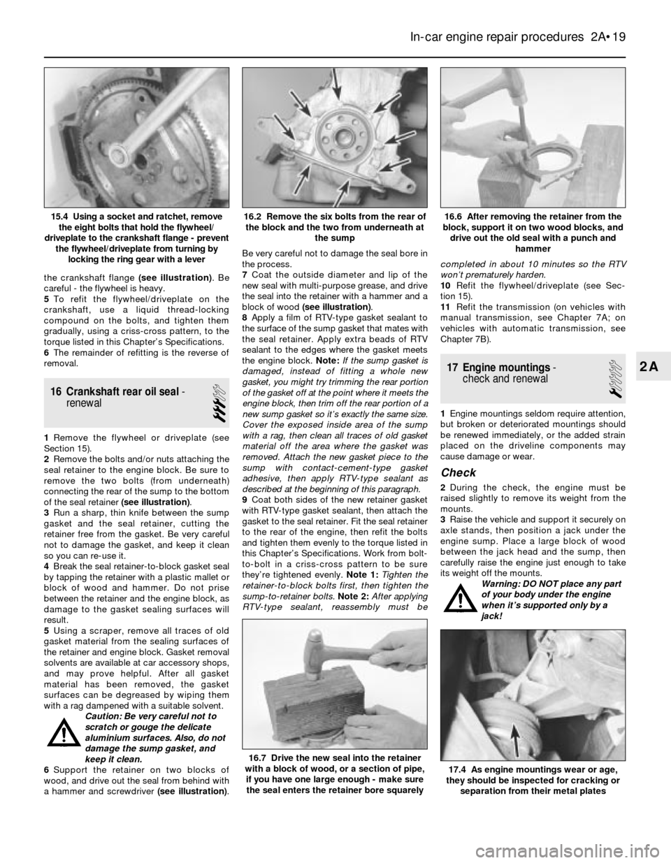
the crankshaft flange (see illustration). Be
careful - the flywheel is heavy.
5To refit the flywheel/driveplate on the
crankshaft, use a liquid thread-locking
compound on the bolts, and tighten them
gradually, using a criss-cross pattern, to the
torque listed in this Chapter’s Specifications.
6The remainder of refitting is the reverse of
removal.
16 Crankshaft rear oil seal-
renewal
3
1Remove the flywheel or driveplate (see
Section 15).
2Remove the bolts and/or nuts attaching the
seal retainer to the engine block. Be sure to
remove the two bolts (from underneath)
connecting the rear of the sump to the bottom
of the seal retainer (see illustration).
3Run a sharp, thin knife between the sump
gasket and the seal retainer, cutting the
retainer free from the gasket. Be very careful
not to damage the gasket, and keep it clean
so you can re-use it.
4Break the seal retainer-to-block gasket seal
by tapping the retainer with a plastic mallet or
block of wood and hammer. Do not prise
between the retainer and the engine block, as
damage to the gasket sealing surfaces will
result.
5Using a scraper, remove all traces of old
gasket material from the sealing surfaces of
the retainer and engine block. Gasket removal
solvents are available at car accessory shops,
and may prove helpful. After all gasket
material has been removed, the gasket
surfaces can be degreased by wiping them
with a rag dampened with a suitable solvent.
Caution: Be very careful not to
scratch or gouge the delicate
aluminium surfaces. Also, do not
damage the sump gasket, and
keep it clean.
6Support the retainer on two blocks of
wood, and drive out the seal from behind with
a hammer and screwdriver (see illustration).Be very careful not to damage the seal bore in
the process.
7Coat the outside diameter and lip of the
new seal with multi-purpose grease, and drive
the seal into the retainer with a hammer and a
block of wood (see illustration).
8Apply a film of RTV-type gasket sealant to
the surface of the sump gasket that mates with
the seal retainer. Apply extra beads of RTV
sealant to the edges where the gasket meets
the engine block. Note:If the sump gasket is
damaged, instead of fitting a whole new
gasket, you might try trimming the rear portion
of the gasket off at the point where it meets the
engine block, then trim off the rear portion of a
new sump gasket so it’s exactly the same size.
Cover the exposed inside area of the sump
with a rag, then clean all traces of old gasket
material off the area where the gasket was
removed. Attach the new gasket piece to the
sump with contact-cement-type gasket
adhesive, then apply RTV-type sealant as
described at the beginning of this paragraph.
9Coat both sides of the new retainer gasket
with RTV-type gasket sealant, then attach the
gasket to the seal retainer. Fit the seal retainer
to the rear of the engine, then refit the bolts
and tighten them evenly to the torque listed in
this Chapter’s Specifications. Work from bolt-
to-bolt in a criss-cross pattern to be sure
they’re tightened evenly.Note 1:Tighten the
retainer-to-block bolts first, then tighten the
sump-to-retainer bolts.Note 2:After applying
RTV-type sealant, reassembly must becompleted in about 10 minutes so the RTV
won’t prematurely harden.
10Refit the flywheel/driveplate (see Sec-
tion 15).
11Refit the transmission (on vehicles with
manual transmission, see Chapter 7A; on
vehicles with automatic transmission, see
Chapter 7B).
17 Engine mountings-
check and renewal
1
1Engine mountings seldom require attention,
but broken or deteriorated mountings should
be renewed immediately, or the added strain
placed on the driveline components may
cause damage or wear.
Check
2During the check, the engine must be
raised slightly to remove its weight from the
mounts.
3Raise the vehicle and support it securely on
axle stands, then position a jack under the
engine sump. Place a large block of wood
between the jack head and the sump, then
carefully raise the engine just enough to take
its weight off the mounts.
Warning: DO NOT place any part
of your body under the engine
when it’s supported only by a
jack!
In-car engine repair procedures 2A•19
16.6 After removing the retainer from the
block, support it on two wood blocks, and
drive out the old seal with a punch and
hammer16.2 Remove the six bolts from the rear of
the block and the two from underneath at
the sump15.4 Using a socket and ratchet, remove
the eight bolts that hold the flywheel/
driveplate to the crankshaft flange - prevent
the flywheel/driveplate from turning by
locking the ring gear with a lever
17.4 As engine mountings wear or age,
they should be inspected for cracking or
separation from their metal plates
16.7 Drive the new seal into the retainer
with a block of wood, or a section of pipe,
if you have one large enough - make sure
the seal enters the retainer bore squarely
2A
Page 61 of 228
otherwise a small brush or even a bicycle tyre
pump will work). The idea is to prevent dirt
from getting into the cylinders as the
compression check is being done.
3Remove all the spark plugs from the engine
(see Chapter 1).
4Block the throttle wide open, or have an
assistant hold the throttle pedal down.
5On carburettor models, disconnect the LT
lead from the coil. On fuel injection models,
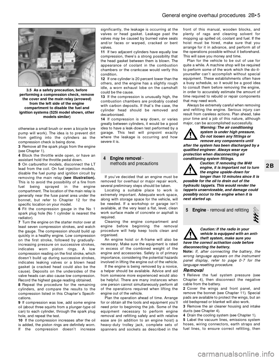
disable the fuel pump and ignition circuit by
removing the main relay(see illustration).
This is to avoid the possibility of a fire from
fuel being sprayed in the engine
compartment. The location of the main relay is
generally near the fuse panel area under the
bonnet, but refer to Chapter 12 for the
specific location on your model.
6Fit the compression gauge in the No 1
spark plug hole (No 1 cylinder is nearest the
radiator).
7Turn the engine on the starter motor over at
least seven compression strokes, and watch
the gauge. The compression should build up
quickly in a healthy engine. Low compression
on the first stroke, followed by gradually-
increasing pressure on successive strokes,
indicates worn piston rings. A low
compression reading on the first stroke, which
doesn’t build up during successive strokes,
indicates leaking valves or a blown head
gasket (a cracked head could also be the
cause). Deposits on the undersides of the
valve heads can also cause low compression.
Record the highest gauge reading obtained.
8Repeat the procedure for the remaining
cylinders, and compare the results to the
compression listed in this Chapter’s Specifi-
cations.
9If compression was low, add some engine
oil (about three squirts from a plunger-type oil
can) to each cylinder, through the spark plug
hole, and repeat the test.
10If the compression increases after the oil
is added, the piston rings are definitely worn.
If the compression doesn’t increasesignificantly, the leakage is occurring at the
valves or head gasket. Leakage past the
valves may be caused by burned valve seats
and/or faces or warped, cracked or bent
valves.
11If two adjacent cylinders have equally low
compression, there’s a strong possibility that
the head gasket between them is blown. The
appearance of coolant in the combustion
chambers or the crankcase would verify this
condition.
12If one cylinder is 20 percent lower than the
others, and the engine has a slightly rough
idle, a worn exhaust lobe on the camshaft
could be the cause.
13If the compression is unusually high, the
combustion chambers are probably coated
with carbon deposits. If that’s the case, the
cylinder head should be removed and
decarbonised.
14If compression is way down, or varies
greatly between cylinders, it would be a good
idea to have a leak-down test performed by a
garage. This test will pinpoint exactly
where the leakage is occurring and how
severe it is.
4 Engine removal-
methods and precautions
If you’ve decided that an engine must be
removed for overhaul or major repair work,
several preliminary steps should be taken.
Locating a suitable place to work is
extremely important. Adequate work space,
along with storage space for the vehicle, will
be needed. If a workshop or garage isn’t
available, at the very least a flat, level, clean
work surface made of concrete or asphalt is
required.
Cleaning the engine compartment and
engine before beginning the removal
procedure will help keep tools clean and
organised.
An engine hoist or A-frame will also be
necessary. Make sure the equipment is rated
in excess of the combined weight of the
engine and accessories. Safety is of primary
importance, considering the potential hazards
involved in lifting the engine out of the vehicle.
If the engine is being removed by a novice,
a helper should be available. Advice and aid
from someone more experienced would also
be helpful. There are many instances when
one person cannot simultaneously perform all
of the operations required when lifting the
engine out of the vehicle.
Plan the operation ahead of time. Arrange
for or obtain all the tools and equipment you’ll
need prior to beginning the job. Some of the
equipment necessary to perform engine
removal and refitting safely and with relative
ease are (in addition to an engine hoist) a
heavy-duty trolley jack, complete sets of
spanners and sockets as described in thefront of this manual, wooden blocks, and
plenty of rags and cleaning solvent for
mopping up spilled oil, coolant and fuel. If the
hoist must be hired, make sure that you
arrange for it in advance, and perform all of
the operations possible without it beforehand.
This will save you money and time.
Plan for the vehicle to be out of use for
quite a while. A machine shop will be required
to perform some of the work which the do-it-
yourselfer can’t accomplish without special
equipment. These establishments often have
a busy schedule, so it would be a good idea
to consult them before removing the engine,
in order to accurately estimate the amount of
time required to rebuild or repair components
that may need work.
Always be extremely careful when removing
and refitting the engine. Serious injury can
result from careless actions. Plan ahead, take
your time and a job of this nature, although
major, can be accomplished successfully.
Warning: The air conditioning
system is under high pressure.
Do not loosen any fittings or
remove any components until
after the system has been discharged by a
qualified engineer. Always wear eye
protection when disconnecting air
conditioning system fittings.
Caution: If removing the M40
engine, it is important not to turn
the engine upside-down for
longer than 10 minutes since it is
possible for the oil to drain out of the
hydraulic tappets. This would render the
tappets unserviceable, and damage could
possibly occur to the engine when it is
next started up.
5 Engine- removal and refitting
3
Caution: If the radio in your
vehicle is equipped with an anti-
theft system, make sure you
have the correct activation code before
disconnecting the battery.
Note: If, after connecting the battery, the
wrong language appears on the instrument
panel display, refer to page 0-7 for the
language resetting procedure.
Removal1Relieve the fuel system pressure (see
Chapter 4), then disconnect the negative
cable from the battery.
2Cover the wings and front panel, and
remove the bonnet (see Chapter 11). Special
pads are available to protect the wings, but an
old bedspread or blanket will also work.
3Remove the air cleaner housing and intake
ducts (see Chapter 4).
4Drain the cooling system (see Chapter 1).
5Label the vacuum lines, emissions system
hoses, wiring connectors, earth straps and
fuel lines, to ensure correct refitting, then
General engine overhaul procedures 2B•5
3.5 As a safety precaution, before
performing a compression check, remove
the cover and the main relay (arrowed)
from the left side of the engine
compartment to disable the fuel and
ignition systems (525i model shown, other
models similar)
2B
Page 62 of 228
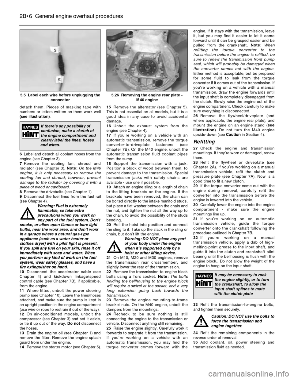
detach them. Pieces of masking tape with
numbers or letters written on them work well
(see illustration).
6Label and detach all coolant hoses from the
engine (see Chapter 3).
7Remove the cooling fan, shroud and
radiator (see Chapter 3). Note:On the M40
engine, it is only necessary to remove the
cooling fan and shroud; however, prevent
damage to the radiator by covering it with a
piece of wood or cardboard.
8Remove the drivebelts (see Chapter 1).
9Disconnect the fuel lines from the fuel rail
(see Chapter 4).
Warning: Fuel is extremely
flammable, so take extra
precautions when you work on
any part of the fuel system. Don’t
smoke, or allow open flames or bare light
bulbs, near the work area, and don’t work
in a garage where a natural gas-type
appliance (such as a water heater or
clothes dryer) with a pilot light is present.
If you spill any fuel on your skin, rinse it off
immediately with soap and water. When
you perform any kind of work on the fuel
system, wear safety glasses, and have a
fire extinguisher on hand.
10Disconnect the accelerator cable (see
Chapter 4) and kickdown linkage/speed
control cable (see Chapter 7B), if applicable,
from the engine.
11Where fitted, unbolt the power steering
pump (see Chapter 10). Leave the lines/hoses
attached, and make sure the pump is kept in
an upright position in the engine compartment
(use wire or rope to restrain it out of the way).
12On air-conditioned models, unbolt the
compressor (see Chapter 3) and set it aside,
or tie it up out of the way. Do not disconnect
the hoses.
13Drain the engine oil (see Chapter 1) and
remove the filter. Remove the engine splash
guard from under the engine.
14Remove the starter motor (see Chapter 5).15Remove the alternator (see Chapter 5).
This is not essential on all models, but it is a
good idea in any case to avoid accidental
damage.
16Unbolt the exhaust system from the
engine (see Chapter 4).
17If you’re working on a vehicle with an
automatic transmission, remove the torque
converter-to-driveplate fasteners (see
Chapter 7B). On the M40 engine, unbolt the
automatic transmission fluid coolant pipes
from the sump.
18Support the transmission with a jack.
Position a block of wood between them, to
prevent damage to the transmission. Special
transmission jacks with safety chains are
available - use one if possible.
19Attach an engine sling or a length of chain
to the lifting brackets on the engine. If the
brackets have been removed, the chain can
be bolted directly to the intake manifold studs,
but place a flat washer between the chain and
the nut, and tighten the nut all the way up to
the chain, to avoid the possibility of the studs
bending.
20Roll the hoist into position and connect
the sling to it. Take up the slack in the sling or
chain, but don’t lift the engine.
Warning: DO NOT place any part
of your body under the engine
when it’s supported only by a
hoist or other lifting device.
21On M10, M20 and M30 engines, remove
the transmission rear crossmember, and
slightly lower the rear of the transmission.
22Remove the transmission-to-engine block
bolts using a Torx socket. Note:The bolts
holding the bellhousing to the engine block
will require a swivel at the socket, and a very
long extension going back towards the
transmission.
23Remove the engine mounting-to-frame
bracket nuts. On the M40 engine, unbolt the
dampers from the mountings.
24Recheck to be sure nothing is still
connecting the engine to the transmission or
vehicle. Disconnect anything still remaining.
25Raise the engine slightly. Carefully work it
forwards to separate it from the transmission.
If you’re working on a vehicle with an
automatic transmission, you may find the
torque converter comes forward with theengine. If it stays with the transmission, leave
it, but you may find it easier to let it come
forward until it can be grasped easier and be
pulled from the crankshaft. Note:When
refitting the torque converter to the
transmission before the engine is refitted, be
sure to renew the transmission front pump
seal, which will probably be damaged when
the converter comes out with the engine.
Either method is acceptable, but be prepared
for some fluid to leak from the torque
converter if it comes out of the transmission. If
you’re working on a vehicle with a manual
transmission, draw the engine forwards until
the input shaft is completely disengaged from
the clutch. Slowly raise the engine out of the
engine compartment. Check carefully to make
sure everything is disconnected.
26Remove the flywheel/driveplate (and
where applicable, the engine rear plate), and
mount the engine on an engine stand (see
illustration). Do not turn the M40 engine
upside-down (see Cautionin Section 4).
Refitting
27Check the engine and transmission
mountings. If they’re worn or damaged, renew
them.
28Refit the flywheel or driveplate (see
Chapter 2A). If you’re working on a manual
transmission vehicle, refit the clutch and
pressure plate (see Chapter 7A). Now is a
good time to fit a new clutch.
29If the torque converter came out with the
engine during removal, carefully refit the
converter into the transmission before the
engine is lowered into the vehicle.
30Carefully lower the engine into the engine
compartment - make sure the engine
mountings line up.
31If you’re working on an automatic
transmission vehicle, guide the torque
converter onto the crankshaft following the
procedure outlined in Chapter 7B.
32If you’re working on a manual
transmission vehicle, apply a dab of high-
melting-point grease to the input shaft, and
guide it into the clutch and crankshaft pilot
bearing until the bellhousing is flush with the
engine block.. Do not allow the weight of the
engine to hang on the input shaft.
33Refit the transmission-to-engine bolts,
and tighten them securely.
Caution: DO NOT use the bolts to
force the transmission and
engine together.
34Refit the remaining components in the
reverse order of removal.
35Add coolant, oil, power steering and
transmission fluid as needed.
2B•6 General engine overhaul procedures
5.26 Removing the engine rear plate -
M40 engine5.5 Label each wire before unplugging the
connector
If there’s any possibility of
confusion, make a sketch of
the engine compartment and
clearly label the lines, hoses
and wires.
It may be necessary to rock
the engine slightly, or to turn
the crankshaft, to allow the
input shaft splines to mate
with the clutch plate
Page 76 of 228
positions (don’t mix them up) with the arrows
pointing towards the front of the engine. Don’t
disturb the Plastigage.
13Starting with the centre main bearing and
working out toward the ends, progressively
tighten the main bearing cap bolts to the
torque listed in this Chapter’s Specifications.
On M10, M20 and M30 engines, tighten the
bolts in three stages. On the M40 engine,
tighten all the bolts initially to the Stage 1
torque, then angle-tighten them by the angle
given in the Specifications. Carry out the
angle-tightening on each bolt in one
controlled movement. Don’t rotate the
crankshaft at any time during the tightening
operation.
14Remove the bolts and carefully lift off the
main bearing caps. Keep them in order. Don’t
disturb the Plastigage or rotate the
crankshaft. If any of the main bearing caps are
difficult to remove, tap them gently from side-
to-side with a soft-face hammer to loosen
them.
15Compare the width of the crushed
Plastigage on each journal to the scale printed
on the Plastigage envelope to obtain the main
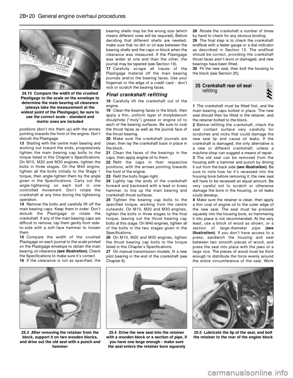
bearing oil clearance (see illustration). Check
the Specifications to make sure it’s correct.
16If the clearance is not as specified, thebearing shells may be the wrong size (which
means different ones will be required). Before
deciding that different shells are needed,
make sure that no dirt or oil was between the
bearing shells and the caps or block when the
clearance was measured. If the Plastigage
was wider at one end than the other, the
journal may be tapered (see Section 19).
17Carefully scrape all traces of the
Plastigage material off the main bearing
journals and/or the bearing faces. Use your
fingernail or the edge of a credit card - don’t
nick or scratch the bearing faces.
Final crankshaft refitting
18Carefully lift the crankshaft out of the
engine.
19Clean the bearing faces in the block, then
apply a thin, uniform layer of molybdenum
disulphide (“moly”) grease or engine oil to
each of the bearing surfaces. Be sure to coat
the thrust faces as well as the journal face of
the thrust bearing.
20Make sure the crankshaft journals are
clean, then lay the crankshaft back in place in
the block.
21Clean the faces of the bearings in the
caps, then apply engine oil to them.
22Refit the caps in their respective
positions, with the arrows pointing towards
the front of the engine.
23Refit the bolts finger-tight.
24Lightly tap the ends of the crankshaft
forward and backward with a lead or brass
hammer, to line up the main bearing and
crankshaft thrust surfaces.
25Tighten the bearing cap bolts to the
specified torque, working from the centre
outwards. On M10, M20 and M30 engines,
tighten the bolts in three stages to the final
torque, leaving out the thrust bearing cap
bolts at this stage. On M40 engines, tighten all
of the bolts in the two stages given in the
Specifications.
26On M10, M20 and M30 engines, tighten
the thrust bearing cap bolts to the torque
listed in this Chapter’s Specifications.
27On manual transmission models, fit a new
pilot bearing in the end of the crankshaft (see
Chapter 8).28Rotate the crankshaft a number of times
by hand to check for any obvious binding.
29The final step is to check the crankshaft
endfloat with a feeler gauge or a dial indicator
as described in Section 13. The endfloat
should be correct, providing the crankshaft
thrust faces aren’t worn or damaged, and new
bearings have been fitted.
30Fit the new seal, then bolt the housing to
the block (see Section 25).
25 Crankshaft rear oil seal-
refitting
3
1The crankshaft must be fitted first, and the
main bearing caps bolted in place. The new
seal should then be fitted in the retainer, and
the retainer bolted to the block.
2Before refitting the crankshaft, check the
seal contact surface very carefully for
scratches and nicks that could damage the
new seal lip and cause oil leaks. If the
crankshaft is damaged, the only alternative is
a new or different crankshaft, unless a
machine shop can suggest a means of repair.
3The old seal can be removed from the
housing with a hammer and punch by driving
it out from the back side (see illustration). Be
sure to note how far it’s recessed into the
housing bore before removing it; the new seal
will have to be recessed an equal amount. Be
very careful not to scratch or otherwise
damage the bore in the housing, or oil leaks
could develop.
4Make sure the retainer is clean, then apply
a thin coat of engine oil to the outer edge of
the new seal. The seal must be pressed
squarely into the housing bore, so hammering
it into place is not recommended. At the very
least, use a block of wood as shown, or a
section of large-diameter pipe (see
illustration). If you don’t have access to a
press, sandwich the housing and seal
between two smooth pieces of wood, and
press the seal into place with the jaws of a
large vice. The pieces of wood must be thick
enough to distribute the force evenly around
the entire circumference of the seal. Work
2B•20 General engine overhaul procedures
25.5 Lubricate the lip of the seal, and bolt
the retainer to the rear of the engine block25.4 Drive the new seal into the retainer
with a wooden block or a section of pipe, if
you have one large enough - make sure
the seal enters the retainer bore squarely25.3 After removing the retainer from the
block, support it on two wooden blocks,
and drive out the old seal with a punch and
hammer
24.15 Compare the width of the crushed
Plastigage to the scale on the envelope to
determine the main bearing oil clearance
(always take the measurement at the
widest point of the Plastigage); be sure to
use the correct scale - standard and
metric ones are included
Page 79 of 228
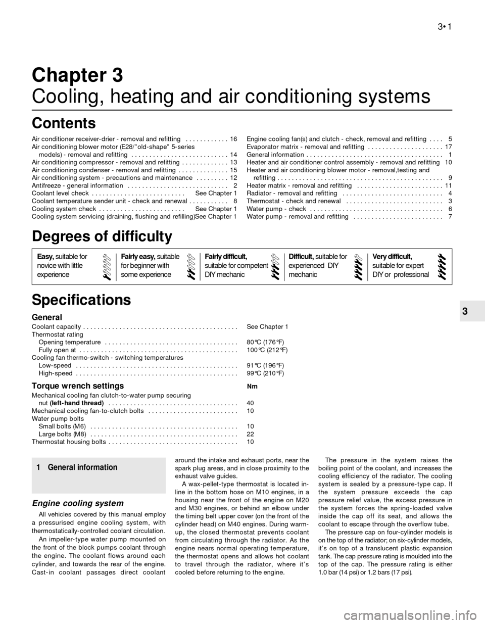
3General
Coolant capacity . . . . . . . . . . . . . . . . . . . . . . . . . . . . . . . . . . . . . . . . . . . See Chapter 1
Thermostat rating
Opening temperature . . . . . . . . . . . . . . . . . . . . . . . . . . . . . . . . . . . . . 80°C (176°F)
Fully open at . . . . . . . . . . . . . . . . . . . . . . . . . . . . . . . . . . . . . . . . . . . . 100°C (212°F)
Cooling fan thermo-switch - switching temperatures
Low-speed . . . . . . . . . . . . . . . . . . . . . . . . . . . . . . . . . . . . . . . . . . . . . 91°C (196°F)
High-speed . . . . . . . . . . . . . . . . . . . . . . . . . . . . . . . . . . . . . . . . . . . . . 99°C (210°F)
Torque wrench settingsNm
Mechanical cooling fan clutch-to-water pump securing
nut (left-hand thread) . . . . . . . . . . . . . . . . . . . . . . . . . . . . . . . . . . . . 40
Mechanical cooling fan-to-clutch bolts . . . . . . . . . . . . . . . . . . . . . . . . . 10
Water pump bolts
Small bolts (M6) . . . . . . . . . . . . . . . . . . . . . . . . . . . . . . . . . . . . . . . . . 10
Large bolts (M8) . . . . . . . . . . . . . . . . . . . . . . . . . . . . . . . . . . . . . . . . . 22
Thermostat housing bolts . . . . . . . . . . . . . . . . . . . . . . . . . . . . . . . . . . . . 10
Chapter 3
Cooling, heating and air conditioning systems
Air conditioner receiver-drier - removal and refitting . . . . . . . . . . . . 16
Air conditioning blower motor (E28/”old-shape” 5-series
models) - removal and refitting . . . . . . . . . . . . . . . . . . . . . . . . . . . 14
Air conditioning compressor - removal and refitting . . . . . . . . . . . . . 13
Air conditioning condenser - removal and refitting . . . . . . . . . . . . . . 15
Air conditioning system - precautions and maintenance . . . . . . . . . 12
Antifreeze - general information . . . . . . . . . . . . . . . . . . . . . . . . . . . . 2
Coolant level check . . . . . . . . . . . . . . . . . . . . . . . . . . See Chapter 1
Coolant temperature sender unit - check and renewal . . . . . . . . . . . 8
Cooling system check . . . . . . . . . . . . . . . . . . . . . . . . See Chapter 1
Cooling system servicing (draining, flushing and refilling)See Chapter 1Engine cooling fan(s) and clutch - check, removal and refitting . . . . 5
Evaporator matrix - removal and refitting . . . . . . . . . . . . . . . . . . . . . 17
General information . . . . . . . . . . . . . . . . . . . . . . . . . . . . . . . . . . . . . . 1
Heater and air conditioner control assembly - removal and refitting 10
Heater and air conditioning blower motor - removal,testing and
refitting . . . . . . . . . . . . . . . . . . . . . . . . . . . . . . . . . . . . . . . . . . . . . . 9
Heater matrix - removal and refitting . . . . . . . . . . . . . . . . . . . . . . . . 11
Radiator - removal and refitting . . . . . . . . . . . . . . . . . . . . . . . . . . . . 4
Thermostat - check and renewal . . . . . . . . . . . . . . . . . . . . . . . . . . . 3
Water pump - check . . . . . . . . . . . . . . . . . . . . . . . . . . . . . . . . . . . . . 6
Water pump - removal and refitting . . . . . . . . . . . . . . . . . . . . . . . . . 7
3•1
Easy,suitable for
novice with little
experienceFairly easy,suitable
for beginner with
some experienceFairly difficult,
suitable for competent
DIY mechanic
Difficult,suitable for
experienced DIY
mechanicVery difficult,
suitable for expert
DIY or professional
Degrees of difficulty
Specifications Contents
1 General information
Engine cooling system
All vehicles covered by this manual employ
a pressurised engine cooling system, with
thermostatically-controlled coolant circulation.
An impeller-type water pump mounted on
the front of the block pumps coolant through
the engine. The coolant flows around each
cylinder, and towards the rear of the engine.
Cast-in coolant passages direct coolantaround the intake and exhaust ports, near the
spark plug areas, and in close proximity to the
exhaust valve guides.
A wax-pellet-type thermostat is located in-
line in the bottom hose on M10 engines, in a
housing near the front of the engine on M20
and M30 engines, or behind an elbow under
the timing belt upper cover (on the front of the
cylinder head) on M40 engines. During warm-
up, the closed thermostat prevents coolant
from circulating through the radiator. As the
engine nears normal operating temperature,
the thermostat opens and allows hot coolant
to travel through the radiator, where it’s
cooled before returning to the engine.The pressure in the system raises the
boiling point of the coolant, and increases the
cooling efficiency of the radiator. The cooling
system is sealed by a pressure-type cap. If
the system pressure exceeds the cap
pressure relief value, the excess pressure in
the system forces the spring-loaded valve
inside the cap off its seat, and allows the
coolant to escape through the overflow tube.
The pressure cap on four-cylinder models is
on the top of the radiator; on six-cylinder models,
it’s on top of a translucent plastic expansion
tank. The cap pressure rating is moulded into the
top of the cap. The pressure rating is either
1.0 bar (14 psi) or 1.2 bars (17 psi).
Page 80 of 228
Warning: Do not remove the
pressure cap from the radiator or
expansion tank until the engine
has cooled completely and
there’s no pressure remaining in the
cooling system. Removing the cap from a
hot engine risks personal injury by
scalding.
Heating system
The heating system consists of a blower fan
and heater matrix located in the heater box,
with hoses connecting the heater matrix to the
engine cooling system, and the heater/air
conditioning control head on the dashboard.
Hot engine coolant is circulated through the
heater matrix passages all the time the engine
is running. Switching the heater on opens a
flap door to direct air through the heater
matrix, and the warmed air enters the
passenger compartment. A fan switch on the
control head activates the blower motor,
which forces more air through the heater
matrix, giving additional heater output for
demisting, etc.
Air conditioning system
The air conditioning system consists of a
condenser mounted in front of the radiator, an
evaporator mounted adjacent to the heater
matrix, a compressor mounted on the engine,
a filter-drier (receiver-drier) which contains a
high-pressure relief valve, and the plumbing
connecting all of the above components.
A blower fan forces the warmer air of the
passenger compartment through the
evaporator matrix (a radiator-in-reverse),
transferring the heat from the air to the
refrigerant. The liquid refrigerant boils off into
low-pressure vapour, taking the heat with it
when it leaves the evaporator.
Note: Refer to the precautions at the start
of Section 12 concerning the potential
dangers associated with the air conditioning
system.
2 Antifreeze-
general information
Warning: Do not allow antifreeze
to come in contact with your skin
or painted surfaces of the
vehicle. Rinse off spills
immediately with plenty of water. If
consumed, antifreeze can be fatal;
children and pets are attracted by its
sweet taste, so wipe up garage floor and
drip pan coolant spills immediately. Keep
antifreeze containers covered, and repair
leaks in your cooling system as soon as
they are noticed.
The cooling system should be filled with a
60/40% water/ethylene-glycol-based anti-
freeze solution, which will prevent freezing
down to approximately -27°C (-17°F). The
antifreeze also raises the boiling point of thecoolant, and (if of good quality) provides
protection against corrosion.
The cooling system should be drained,
flushed and refilled at the specified intervals
(see Chapter 1). Old or contaminated
antifreeze solutions are likely to cause
damage, and encourage the formation of rust
and scale in the system. Use distilled water
with the antifreeze, if available, or clean
rainwater. Tap water will do, but not if the
water in your area is at all “hard”.
Before adding antifreeze, check all hose
connections, because antifreeze tends to
search out and leak through very minute
openings. Engines don’t normally consume
coolant, so if the level goes down, find the
cause and correct it.
The antifreeze mixture should be
maintained at its correct proportions; adding
too much antifreeze reduces the efficiency of
the cooling system. If necessary, consult the
mixture ratio chart on the antifreeze container
before adding coolant. Hydrometers are
available at most car accessory shops to test
the coolant. Use antifreeze which meets the
vehicle manufacturer’s specifications.
3 Thermostat-
check and renewal
1
Warning: Do not remove the
radiator cap, drain the coolant, or
renew the thermostat until the
engine has cooled completely.
Check
1Before assuming the thermostat is to blame
for a cooling system problem, check the
coolant level, drivebelt tension (see Chapter 1)
and temperature gauge (or warning light)
operation.
2If the engine seems to be taking a long time
to warm up (based on heater output or
temperature gauge operation), the thermostat
is probably stuck open. Renew the
thermostat.
3If the engine runs hot, use your hand to
check the temperature of the upper radiator
hose. If the hose isn’t hot, but the engine is,
the thermostat is probably stuck closed,preventing the coolant inside the engine from
circulating to the radiator. Renew the
thermostat.
Caution: Don’t drive the vehicle
without a thermostat. The engine
will be very slow to warm-up in
cold conditions, resulting in poor
fuel economy and driveability. A new
thermostat is normally an inexpensive
component anyway.
4If the upper radiator hose is hot, it means
that the coolant is flowing and the thermostat
is at least partly open. Consult the “Fault
finding” Section at the rear of this manual for
cooling system diagnosis.
Renewal
All models
5Disconnect the negative cable from the
battery.
Caution: If the radio in your
vehicle is equipped with an anti-
theft system, make sure you
have the correct activation code
before disconnecting the battery.
Note: If, after connecting the battery, the
wrong language appears on the instrument
panel display, refer to page 0-7 for the
language resetting procedure.
6Drain the cooling system (see Chapter 1). If
the coolant is relatively new or in good
condition, save it and re-use it.
M10 engines
7The thermostat is located in the bottom
hose. First remove the cooling fan.
8Note the fitted position of the thermostat,
then unscrew the hose clamps and withdraw
the thermostat from the hose connections
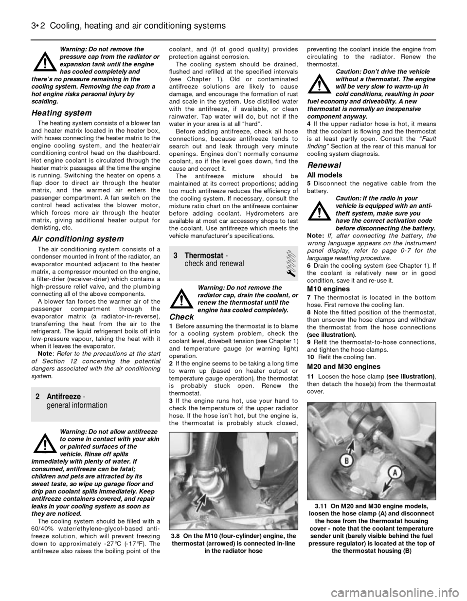
(see illustration).
9Refit the thermostat-to-hose connections,
and tighten the hose clamps.
10Refit the cooling fan.
M20 and M30 engines
11Loosen the hose clamp (see illustration),
then detach the hose(s) from the thermostat
cover.
3•2 Cooling, heating and air conditioning systems
3.11 On M20 and M30 engine models,
loosen the hose clamp (A) and disconnect
the hose from the thermostat housing
cover - note that the coolant temperature
sender unit (barely visible behind the fuel
pressure regulator) is located at the top of
the thermostat housing (B)
3.8 On the M10 (four-cylinder) engine, the
thermostat (arrowed) is connected in-line
in the radiator hose
Page 85 of 228
4If a new sender unit is to be fitted, make
sure the engine is completely cool. There will
be some coolant loss when the unit is
unscrewed, so be prepared to catch it, or
have the new unit ready to fit immediately the
old one is removed. Disconnect the wiring,
then unscrew the old unit from the engine,
and fit the new one. Use sealant on the
threads. Reconnect the wiring, and check the
coolant level on completion.
9 Heater and air conditioning
blower motor- removal,
testing and refitting
1
Removal
Note: The 3-Series models covered by this
manual have always used a single blower
motor for ventilation, heating and air
conditioning. “Old-shape” (E28) 5-Series
models use two separate blower motors: one
for ventilation and heating, and another for air
conditioning. “New-shape” (E34) 5-Series
models have a single blower motor, like the 3-
Series. The removal and refitting of the single
blower motor, and the old-shape 5-Series
vent/heat motor, is described below. The
removal and refitting of the old-shape 5-Series
air conditioning blower motor is described in
Section 14 of this Chapter.
Caution: If the radio in your
vehicle is equipped with an anti-
theft system, make sure you have
the correct activation code
before disconnecting the battery.
Note: If, after connecting the battery, the
wrong language appears on the instrument
panel display, refer to page 0-7 for the
language resetting procedure.
1Disconnect the battery negative cable.
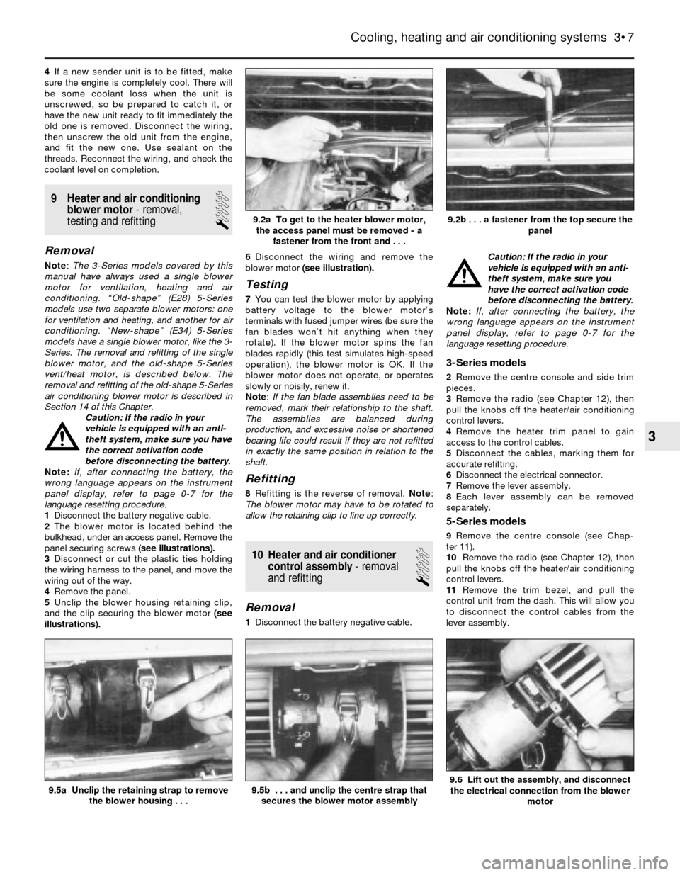
2The blower motor is located behind the
bulkhead, under an access panel. Remove the
panel securing screws (see illustrations).
3Disconnect or cut the plastic ties holding
the wiring harness to the panel, and move the
wiring out of the way.
4Remove the panel.
5Unclip the blower housing retaining clip,
and the clip securing the blower motor (see
illustrations).6Disconnect the wiring and remove the
blower motor (see illustration).
Testing
7You can test the blower motor by applying
battery voltage to the blower motor’s
terminals with fused jumper wires (be sure the
fan blades won’t hit anything when they
rotate). If the blower motor spins the fan
blades rapidly (this test simulates high-speed
operation), the blower motor is OK. If the
blower motor does not operate, or operates
slowly or noisily, renew it.
Note: If the fan blade assemblies need to be
removed, mark their relationship to the shaft.
The assemblies are balanced during
production, and excessive noise or shortened
bearing life could result if they are not refitted
in exactly the same position in relation to the
shaft.
Refitting
8Refitting is the reverse of removal. Note:
The blower motor may have to be rotated to
allow the retaining clip to line up correctly.
10 Heater and air conditioner
control assembly- removal
and refitting
1
Removal
1Disconnect the battery negative cable. Caution: If the radio in your
vehicle is equipped with an anti-
theft system, make sure you
have the correct activation code
before disconnecting the battery.
Note: If, after connecting the battery, the
wrong language appears on the instrument
panel display, refer to page 0-7 for the
language resetting procedure.
3-Series models
2Remove the centre console and side trim
pieces.
3Remove the radio (see Chapter 12), then
pull the knobs off the heater/air conditioning
control levers.
4Remove the heater trim panel to gain
access to the control cables.
5Disconnect the cables, marking them for
accurate refitting.
6Disconnect the electrical connector.
7Remove the lever assembly.
8Each lever assembly can be removed
separately.
5-Series models
9Remove the centre console (see Chap-
ter 11).
10Remove the radio (see Chapter 12), then
pull the knobs off the heater/air conditioning
control levers.
11Remove the trim bezel, and pull the
control unit from the dash. This will allow you
to disconnect the control cables from the
lever assembly.
Cooling, heating and air conditioning systems 3•7
9.5a Unclip the retaining strap to remove
the blower housing . . .
9.2b . . . a fastener from the top secure the
panel9.2a To get to the heater blower motor,
the access panel must be removed - a
fastener from the front and . . .
9.6 Lift out the assembly, and disconnect
the electrical connection from the blower
motor9.5b . . . and unclip the centre strap that
secures the blower motor assembly
3
Page 86 of 228
12Disconnect the cables from the clips
securing them to the lever assembly, marking
them for accurate refitting.
13Disconnect the electrical connection from
the control assembly.
14Remove the screws attaching the bezel to
the control assembly, and remove the control
assembly.
Refitting
15Refitting is the reverse of the removal
procedure.
11 Heater matrix-
removal and refitting
1
Caution: If the radio in your
vehicle is equipped with an anti-
theft system, make sure you
have the correct activation code
before disconnecting the battery.
Note: If, after connecting the battery, the
wrong language appears on the instrument
panel display, refer to page 0-7 for the
language resetting procedure.
1Disconnect the battery negative cable.
2Drain the cooling system (see Chapter 1).
3Remove the centre console (see Chap-
ter 11). Spread an old blanket over the front
carpeting; this will prevent stains if any
residual coolant spills.
Removal
3-Series models
4Remove the left-hand side heater ducting,
and set it aside.
5Remove the heater valve clamp.
6Remove the screws and detach the flange
where the two coolant lines enter the heater
matrix case. Be careful; some coolant may
spill.
7Remove the two screws holding the heater
matrix case to the heater main assembly.
8Slide the heater matrix out of the mounting.
Be careful not to spill any of the remaining
coolant in the heater matrix when removing it.
5-Series models
9Disconnect the temperature sensor
electrical connectors.
10Disconnect the straps holding the wiring
to the case, and set the wiring out of the way.
11Unfasten the cover fasteners.
12Remove the screws holding the cover in
place, then remove the cover.
13Disconnect all heater pipe connections
attached to the heater matrix. Be careful;
some coolant may spill.
14Lifting on the right side of the heater
matrix first, remove the heater matrix.
Refitting
Note: Always use new O-rings when attaching
the coolant lines to the heater matrix.15Refitting is the reverse of removal. Refill
the cooling system (see Chapter 1), then run
the engine with the heater on, and check for
correct operation and leaks.
12 Air conditioning system-
precautions and maintenance
1
Precautions
Warning: The air conditioning
system is under high pressure.
DO NOT loosen any hose or line
fittings, or remove any
components, until after the system has
been discharged. Air conditioning
refrigerant should be properly discharged
by a qualified refrigeration engineer. The
refrigerant used in the system must not be
allowed into contact with your skin or
eyes, or there is a risk of frostbite. Should
the refrigerant come into contact with a
naked flame, a poisonous gas will be
produced. Smoking in the presence of
refrigerant is therefore highly dangerous,
particularly if refrigerant vapour is inhaled
through a lighted cigarette. The refrigerant
is heavier than air, and it may cause
suffocation if discharged in an enclosed
space such as a domestic garage.
Finally, uncontrolled release of the
refrigerant causes environmental damage,
by contributing to the “greenhouse
effect”.
Maintenance
1The following maintenance checks should
be performed on a regular basis to ensure the
air conditioner continues to operate at peak
efficiency:
a) Check the drivebelt. If it’s worn or
deteriorated, renew it (see Chapter 1).
b) Check the system hoses. Look for cracks,
bubbles, hard spots and deterioration.
Inspect the hoses and all fittings for oil
bubbles and seepage. If there’s any
evidence of wear, damage or leaks, have
new hose(s) fitted.
c) Inspect the condenser fins for leaves, flies
and other debris. Use a “fin comb” or
compressed air to clean the condenser.
d) Make sure the system has the correct
refrigerant charge, as described below.
2It’s a good idea to operate the system for
about 10 minutes at least once a month,
particularly during the winter. Long-term non-
use can cause hardening, and subsequent
failure, of the seals.
3Because of the complexity of the air
conditioning system and the special
equipment necessary to service it, in-depth
fault diagnosis and repair procedures are not
included in this manual. However, simple
checks and component renewal procedures
are provided in this Chapter.
4The most common cause of poor cooling issimply a low system refrigerant charge. If a
noticeable loss of cool air output occurs, the
following quick check may help you determine
if the refrigerant level is low.
5Warm the engine up to normal operating
temperature.
6Set the air conditioning temperature
selector at the coldest setting, and put the
blower at the highest setting. Open the doors
(to make sure the air conditioning system
doesn’t switch off as soon as it cools the
passenger compartment).
7With the compressor engaged - the
compressor clutch will make an audible click,
and the centre of the clutch will rotate - feel
the tube located adjacent to the right front
frame rail, near the radiator.
8If a significant temperature drop is noticed,
the refrigerant level is probably OK.
9If the inlet line has frost accumulation, or
feels cooler than the receiver-drier surface,
the refrigerant charge is low. Recharging the
system should be carried out by a qualified
refrigeration engineer.
13 Air conditioning compressor
- removal and refitting
5
Warning: Due to the potential
dangers associated with the
system, you are strongly advised
to have any work on the air
conditioning system carried out by a BMW
dealer or air conditioning specialist. At the
very least, DO NOT dismantle any part of
the system (hoses, compressor, line
fittings, etc.) until after the system has
been discharged by a qualified engineer.
Refer to the precautions given at the start
of Section 12.
Note: If a new compressor is fitted, the
receiver-drier (see Section 16) should also be
renewed.
Removal
1Have the air conditioning system
discharged (see Warning above).
2Disconnect the battery negative cable.
Caution: If the radio in your
vehicle is equipped with an anti-
theft system, make sure you
have the correct activation code
before disconnecting the battery.
Note: If, after connecting the battery, the
wrong language appears on the instrument
panel display, refer to page 0-7 for the
language resetting procedure.
3Disconnect the compressor clutch wiring
harness.
4Remove the drivebelt (see Chapter 1).
5Disconnect the refrigerant lines from the
rear of the compressor. Plug the open fittings
to prevent entry of dirt and moisture.
6Unbolt the compressor from the mounting
3•8 Cooling, heating and air conditioning systems
Page 91 of 228
information on removing and refitting the
intake manifold, refer to Chapter 2A.
The throttle valve inside the throttle body or
carburettor is actuated by the accelerator
cable. When you depress the accelerator
pedal, the throttle plate opens and airflow
through the intake system increases.
On fuel injection systems, a flap inside the
airflow meter opens wider as the airflow
increases. A throttle position switch attached
to the pivot shaft of the flap detects the angle
of the flap (how much it’s open) and converts
this to a voltage signal, which it sends to the
computer.
Fuel system
On carburettor models, the fuel pump
supplies fuel under pressure to the
carburettor. A needle valve in the float
chamber maintains the fuel at a constant
level. A fuel return system channels excess
fuel back to the fuel tank.
On fuel injection models, an electric fuel
pump supplies fuel under constant pressure
to the fuel rail, which distributes fuel to the
injectors. The electric fuel pump is located
inside the fuel tank on later models, or beside
the fuel tank on early models. Early models
also have a transfer pump located in the fuel
tank. The transfer pump acts as an aid to the
larger main pump for delivering the necessary
pressure. A fuel pressure regulator controls
the pressure in the fuel system. The fuel
system also has a fuel pulsation damper
located near the fuel filter. The damper
reduces the pressure pulsations caused by
fuel pump operation, and the opening and
closing of the injectors. The amount of fuel
injected into the intake ports is precisely
controlled by an Electronic Control Unit (ECU
or computer). Some later 5-Series models
have a fuel cooler in the return line.
Electronic control system (fuel
injection system)
Besides altering the injector opening
duration as described above, the electronic
control unit performs a number of other tasks
related to fuel and emissions control. It
accomplishes these tasks by using data
relayed to it by a wide array of information
sensors located throughout the enginecompartment, comparing this information to
its stored map, and altering engine operation
by controlling a number of different actuators.
Since special equipment is required, most
fault diagnosis and repair of the electronic
control system is beyond the scope of the
home mechanic. Additional information and
testing procedures for the emissions system
components (oxygen sensor, coolant
temperature sensor, EVAP system, etc.) is
contained in Chapter 6.
2 Fuel injection system-
depressurising
1
Warning: Fuel is extremely
flammable, so take extra
precautions when you work on
any part of the fuel system. Don’t
smoke or allow open flames or bare light
bulbs near the work area. Also, don’t work
in a garage where a natural gas-type
appliance with a pilot light is present.
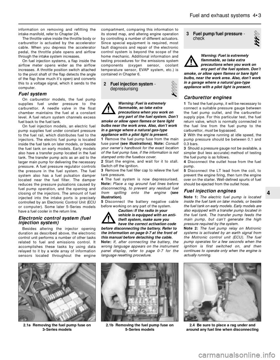
1Remove the fuel pump fuse from the main
fuse panel (see illustrations). Note:Consult
your owner’s handbook for the exact location
of the fuel pump fuse, if the information is not
stamped onto the fusebox cover.
2Start the engine, and wait for it to stall.
Switch off the ignition.
3Remove the fuel filler cap to relieve the fuel
tank pressure.
4The fuel system is now depressurised.
Note:Place a rag around fuel lines before
disconnecting, to prevent any residual fuel
from spilling onto the engine(see
illustration).
5Disconnect the battery negative cable
before working on any part of the system.
Caution: If the radio in your
vehicle is equipped with an anti-
theft system, make sure you
have the correct activation code
before disconnecting the battery. Refer to
the information on page 0-7 at the front of
this manual before detaching the cable.
Note: If, after connecting the battery, the
wrong language appears on the instrument
panel display, refer to page 0-7 for the
language resetting procedure.
3 Fuel pump/fuel pressure-
check
3
Warning: Fuel is extremely
flammable, so take extra
precautions when you work on
any part of the fuel system. Don’t
smoke, or allow open flames or bare light
bulbs, near the work area. Also, don’t work
in a garage where a natural gas-type
appliance with a pilot light is present.
Carburettor engines
1To test the fuel pump, it will be necessary to
connect a suitable pressure gauge between
the fuel pump outlet, and the carburettor
supply pipe. For this particular test, the fuel
return valve, which is normally connected in
the fuel line from the fuel pump to the
carburettor, mustbe bypassed.
2With the engine running at idle speed, the
pump pressure should be between 0.1 and
0.3 bars.
3Should a pressure gauge not be available, a
simpler (but less accurate) method of testing
the fuel pump is as follows.
4Disconnect the outlet hose from the fuel
pump.
5Disconnect the LT lead from the coil, to
prevent the engine firing, then turn the engine
over on the starter. Well-defined spurts of fuel
should be ejected from the outlet hose.
Fuel injection engines
Note 1:The electric fuel pump is located
inside the fuel tank on later models, or beside
the fuel tank on early models. Early models are
also equipped with a transfer pump located in
the fuel tank. The transfer pump feeds the
main pump, but can’t generate the high
pressure required by the system.
Note 2:The fuel pump relay on Motronic
systems is activated by an earth signal from
the Motronic control unit (ECU). The fuel
pump operates for a few seconds when the
ignition is first switched on, and then
continues to operate only when the engine is
actually running.
Fuel and exhaust systems 4•3
2.4 Be sure to place a rag under and
around any fuel line when disconnecting2.1b Removing the fuel pump fuse on
5-Series models2.1a Removing the fuel pump fuse on
3-Series models
4
Page 92 of 228
Note 3:The following checks assume the fuel
filter is in good condition. If you doubt the
condition of your fuel filter, renew it (see
Chapter 1).
Note 4:In order to get accurate test results, it
is recommended that the fuel pressure be
checked from both the main fuel pump and
transfer pump where applicable.
Fuel pump/transfer pump operational
check
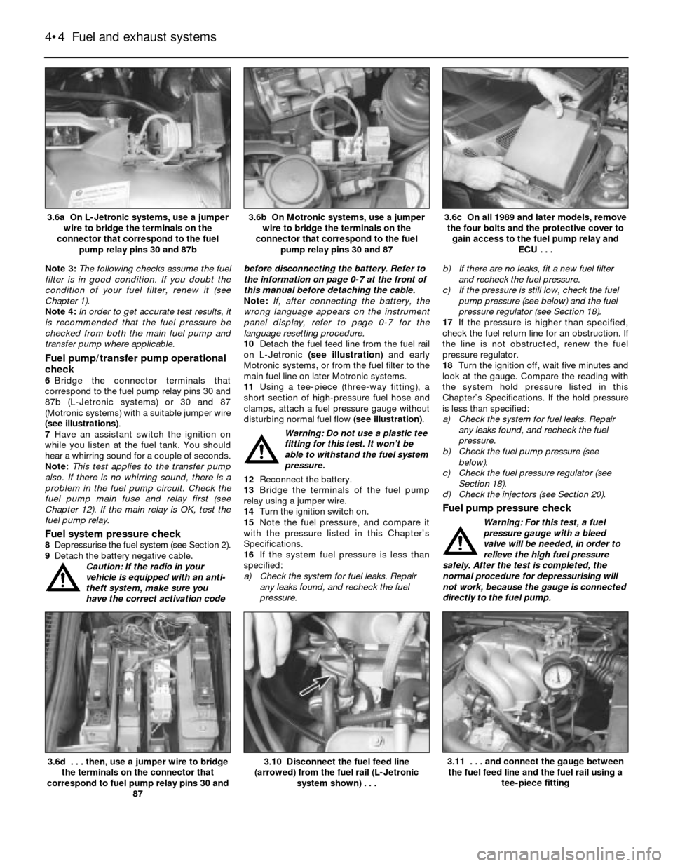
6Bridge the connector terminals that
correspond to the fuel pump relay pins 30 and
87b (L-Jetronic systems) or 30 and 87
(Motronic systems) with a suitable jumper wire
(see illustrations).
7Have an assistant switch the ignition on
while you listen at the fuel tank. You should
hear a whirring sound for a couple of seconds.
Note:This test applies to the transfer pump
also. If there is no whirring sound, there is a
problem in the fuel pump circuit. Check the
fuel pump main fuse and relay first (see
Chapter 12). If the main relay is OK, test the
fuel pump relay.
Fuel system pressure check8Depressurise the fuel system (see Section 2).
9Detach the battery negative cable.
Caution: If the radio in your
vehicle is equipped with an anti-
theft system, make sure you
have the correct activation codebefore disconnecting the battery. Refer to
the information on page 0-7 at the front of
this manual before detaching the cable.
Note: If, after connecting the battery, the
wrong language appears on the instrument
panel display, refer to page 0-7 for the
language resetting procedure.
10Detach the fuel feed line from the fuel rail
on L-Jetronic (see illustration)and early
Motronic systems, or from the fuel filter to the
main fuel line on later Motronic systems.
11Using a tee-piece (three-way fitting), a
short section of high-pressure fuel hose and
clamps, attach a fuel pressure gauge without
disturbing normal fuel flow (see illustration).
Warning: Do not use a plastic tee
fitting for this test. It won’t be
able to withstand the fuel system
pressure.
12Reconnect the battery.
13Bridge the terminals of the fuel pump
relay using a jumper wire.
14Turn the ignition switch on.
15Note the fuel pressure, and compare it
with the pressure listed in this Chapter’s
Specifications.
16If the system fuel pressure is less than
specified:
a) Check the system for fuel leaks. Repair
any leaks found, and recheck the fuel
pressure.b) If there are no leaks, fit a new fuel filter
and recheck the fuel pressure.
c) If the pressure is still low, check the fuel
pump pressure (see below) and the fuel
pressure regulator (see Section 18).
17If the pressure is higher than specified,
check the fuel return line for an obstruction. If
the line is not obstructed, renew the fuel
pressure regulator.
18Turn the ignition off, wait five minutes and
look at the gauge. Compare the reading with
the system hold pressure listed in this
Chapter’s Specifications. If the hold pressure
is less than specified:
a) Check the system for fuel leaks. Repair
any leaks found, and recheck the fuel
pressure.
b) Check the fuel pump pressure (see
below).
c) Check the fuel pressure regulator (see
Section 18).
d) Check the injectors (see Section 20).
Fuel pump pressure check
Warning: For this test, a fuel
pressure gauge with a bleed
valve will be needed, in order to
relieve the high fuel pressure
safely. After the test is completed, the
normal procedure for depressurising will
not work, because the gauge is connected
directly to the fuel pump.
4•4 Fuel and exhaust systems
3.10 Disconnect the fuel feed line
(arrowed) from the fuel rail (L-Jetronic
system shown) . . .3.6d . . . then, use a jumper wire to bridge
the terminals on the connector that
correspond to fuel pump relay pins 30 and
87
3.6c On all 1989 and later models, remove
the four bolts and the protective cover to
gain access to the fuel pump relay and
ECU . . .3.6b On Motronic systems, use a jumper
wire to bridge the terminals on the
connector that correspond to the fuel
pump relay pins 30 and 873.6a On L-Jetronic systems, use a jumper
wire to bridge the terminals on the
connector that correspond to the fuel
pump relay pins 30 and 87b
3.11 . . . and connect the gauge between
the fuel feed line and the fuel rail using a
tee-piece fitting