tire BMW 3 SERIES 1987 E30 User Guide
[x] Cancel search | Manufacturer: BMW, Model Year: 1987, Model line: 3 SERIES, Model: BMW 3 SERIES 1987 E30Pages: 228, PDF Size: 7.04 MB
Page 78 of 228
the bearing - use your fingernail or the edge of
a credit card.
20Make sure the bearing faces are perfectly
clean, then apply a uniform layer of
molybdenum disulphide (“moly”) grease or
engine assembly oil to both of them. You’ll
have to push the piston into the cylinder to
expose the face of the bearing shell in the
connecting rod - be sure to slip the protective
hoses over the rod bolts first, where
applicable.
21Slide the connecting rod back into place
on the journal, and remove the protective
hoses from the rod cap bolts. Refit the rod
cap, and tighten the nuts/bolts to the
specified torque.
22Repeat the entire procedure for the
remaining pistons/connecting rods.
23The important points to remember are:
a) Keep the back sides of the bearing shells
and the insides of the connecting rods
and caps perfectly clean when
assembling them.
b) Make sure you have the correct
piston/rod assembly for each cylinder.
c) The notch or mark on the piston must
face the front of the engine.
d) Lubricate the cylinder walls with clean oil.
e) Lubricate the bearing faces when refitting
the rod caps after the oil clearance has
been checked.
24After all the piston/connecting rod
assemblies have been properly fitted, rotate
the crankshaft a number of times by hand to
check for any obvious binding.25Check the connecting rod side play (see
Section 13).
26Compare the measured side play to the
Specifications to make sure it’s correct. If it
was correct before dismantling, and the
original crankshaft and rods were refitted, it
should still be right. If new rods or a new
crankshaft were fitted, the side play may be
incorrect. If so, the rods will have to be
removed and taken to a machine shop for
attention.
27 Initial start-up and running-
in after overhaul
1
Warning:Have a fire extinguisher
handy when starting the engine
for the first time.
1Once the engine has been refitted in the
vehicle, double-check the engine oil and
coolant levels.
2With the spark plugs removed and the
ignition system disabled (see Section 3), crank
the engine until oil pressure registers on the
gauge, or until the oil pressure warning light
goes out.
3Refit the spark plugs, connect the HT leads,
and restore the ignition system functions (see
Section 3).
4Start the engine. It may take a few
moments for the fuel system to build uppressure, but the engine should start without
a great deal of effort. Note: If backfiring
occurs through the throttle body or
carburettor, check the valve timing (check that
the timing chain/belt has been correctly fitted),
the firing order (check the fitted order of the
spark plug HT leads), and the ignition timing.
5After the engine starts, it should be allowed
to warm up to normal operating temperature.
While the engine is warming up, make a
thorough check for fuel, oil and coolant leaks.
6Shut the engine off and recheck the engine
oil and coolant levels.
7Drive the vehicle to an area with minimum
traffic, accelerate at full throttle from 30 to
50 mph, then lift off the throttle completely,
and allow the vehicle to slow to 30 mph with
the throttle closed. Repeat the procedure
10 or 12 times. This will load the piston rings,
and cause them to seat properly against the
cylinder walls. Check again for oil and coolant
leaks.
8Drive the vehicle gently for the first
500 miles (no sustained high speeds) and
keep a constant check on the oil level. It is not
unusual for an engine to use oil during the
running-in period.
9At approximately 500 to 600 miles, change
the oil and filter.
10For the next few hundred miles, drive the
vehicle normally - don’t nurse it, but don’t
abuse it, either.
11After 2000 miles, change the oil and filter
again. The engine may now be considered to
be fully run-in.
2B•22 General engine overhaul procedures
Page 112 of 228
1 General information
The engine electrical systems include all
ignition, charging and starting components.
Because of their engine-related functions,
these components are discussed separately
from body-related electrical devices such as
the lights, the instruments, etc. (which are
included in Chapter 12).
Always observe the following precautions
when working on the electrical systems:
a) Be extremely careful when servicing
engine electrical components. They are
easily damaged if improperly checked,
connected or handled.
b) Never leave the ignition switched on for
long periods of time with the engine off.
c) Don’t disconnect the battery cables while
the engine is running.
d) Observe the rules when jump-starting
your vehicle. Read the precautions at the
front of this manual.
e) Always disconnect the battery negative
cable first, and connect it last, to reduce
the risk of accidental short-circuits.
f) Don’t charge the battery with the cables
connected to the terminals.
It’s also a good idea to review the safety-
related information regarding the engine
electrical systems in the “Safety first”section
near the front of this manual before beginning
any operation included in this Chapter.
Caution: If the radio in your
vehicle is equipped with an anti-
theft system, make sure you
have the correct activation code
before disconnecting the battery. Refer to
the information on page 0-7 at the front of
this manual before detaching the cable.
Note: If, after connecting the battery, the
wrong language appears on the instrument
panel display, refer to page 0-7 for the
language resetting procedure.
2 Battery-
emergency jump starting
1
Refer to the “Jump starting”procedure at
the front of this manual.
3 Battery- removal and refitting
1
Note:Depending on the model, the battery
may be located in the engine compartment, in
the rear luggage compartment, or under the
rear seat. Consult your owners handbook for
the location of the battery, if not already
known to you.Caution: If the radio in your
vehicle is equipped with an anti-
theft system, make sure you
have the correct activation code
before disconnecting the battery. Refer to
the information on page 0-7 at the front of
this manual before detaching the cable.
Note: If, after connecting the battery, the
wrong language appears on the instrument
panel display, refer to page 0-7 for the
language resetting procedure.
1Disconnect the battery negative cable.
2Detach the cable from the positive terminal.
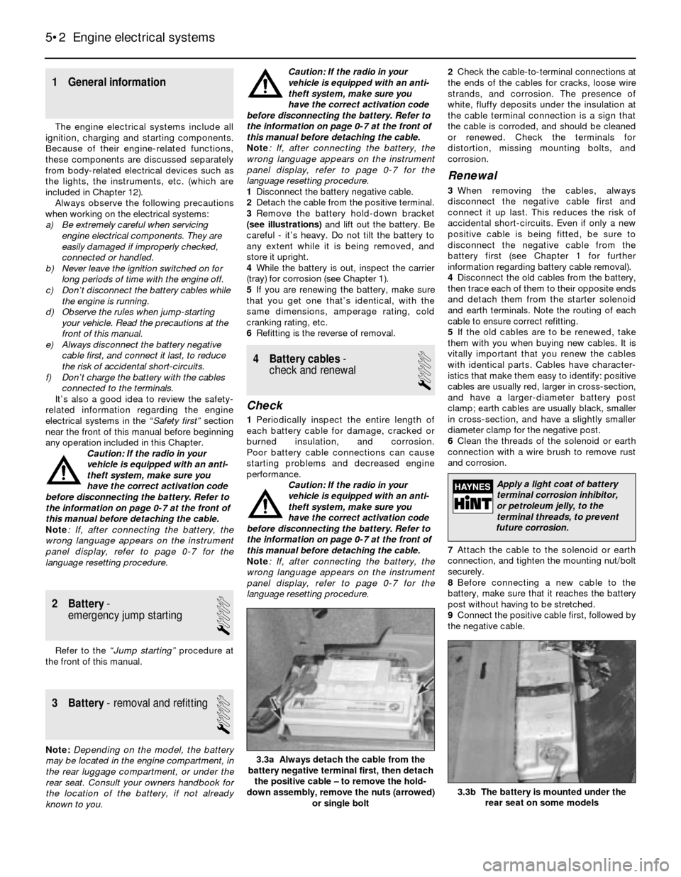
3Remove the battery hold-down bracket
(see illustrations)and lift out the battery. Be
careful - it’s heavy. Do not tilt the battery to
any extent while it is being removed, and
store it upright.
4While the battery is out, inspect the carrier
(tray) for corrosion (see Chapter 1).
5If you are renewing the battery, make sure
that you get one that’s identical, with the
same dimensions, amperage rating, cold
cranking rating, etc.
6Refitting is the reverse of removal.
4 Battery cables-
check and renewal
1
Check
1Periodically inspect the entire length of
each battery cable for damage, cracked or
burned insulation, and corrosion.
Poor battery cable connections can cause
starting problems and decreased engine
performance.
Caution: If the radio in your
vehicle is equipped with an anti-
theft system, make sure you
have the correct activation code
before disconnecting the battery. Refer to
the information on page 0-7 at the front of
this manual before detaching the cable.
Note: If, after connecting the battery, the
wrong language appears on the instrument
panel display, refer to page 0-7 for the
language resetting procedure.2Check the cable-to-terminal connections at
the ends of the cables for cracks, loose wire
strands, and corrosion. The presence of
white, fluffy deposits under the insulation at
the cable terminal connection is a sign that
the cable is corroded, and should be cleaned
or renewed. Check the terminals for
distortion, missing mounting bolts, and
corrosion.
Renewal
3When removing the cables, always
disconnect the negative cable first and
connect it up last. This reduces the risk of
accidental short-circuits. Even if only a new
positive cable is being fitted, be sure to
disconnect the negative cable from the
battery first (see Chapter 1 for further
information regarding battery cable removal).
4Disconnect the old cables from the battery,
then trace each of them to their opposite ends
and detach them from the starter solenoid
and earth terminals. Note the routing of each
cable to ensure correct refitting.
5If the old cables are to be renewed, take
them with you when buying new cables. It is
vitally important that you renew the cables
with identical parts. Cables have character-
istics that make them easy to identify: positive
cables are usually red, larger in cross-section,
and have a larger-diameter battery post
clamp; earth cables are usually black, smaller
in cross-section, and have a slightly smaller
diameter clamp for the negative post.
6Clean the threads of the solenoid or earth
connection with a wire brush to remove rust
and corrosion.
7Attach the cable to the solenoid or earth
connection, and tighten the mounting nut/bolt
securely.
8Before connecting a new cable to the
battery, make sure that it reaches the battery
post without having to be stretched.
9Connect the positive cable first, followed by
the negative cable.
5•2 Engine electrical systems
3.3b The battery is mounted under the
rear seat on some models
3.3a Always detach the cable from the
battery negative terminal first, then detach
the positive cable – to remove the hold-
down assembly, remove the nuts (arrowed)
or single bolt
Apply a light coat of battery
terminal corrosion inhibitor,
or petroleum jelly, to the
terminal threads, to prevent
future corrosion.
Page 124 of 228
4 Information sensors
2
Note:Refer to Chapters 4 and 5 for additional
information on the location and diagnosis of
the information sensors that are not covered in
this Section.
Coolant temperature sensor
General description
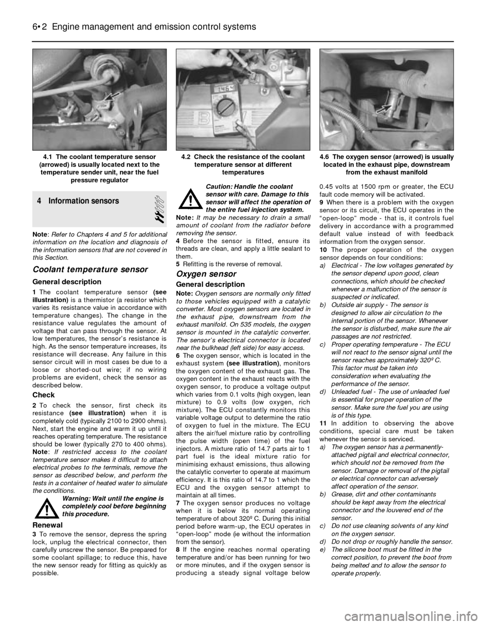
1The coolant temperature sensor (see
illustration)is a thermistor (a resistor which
varies its resistance value in accordance with
temperature changes). The change in the
resistance value regulates the amount of
voltage that can pass through the sensor. At
low temperatures, the sensor’s resistance is
high. As the sensor temperature increases, its
resistance will decrease. Any failure in this
sensor circuit will in most cases be due to a
loose or shorted-out wire; if no wiring
problems are evident, check the sensor as
described below.
Check
2To check the sensor, first check its
resistance (see illustration)when it is
completely cold (typically 2100 to 2900 ohms).
Next, start the engine and warm it up until it
reaches operating temperature. The resistance
should be lower (typically 270 to 400 ohms).
Note: If restricted access to the coolant
temperature sensor makes it difficult to attach
electrical probes to the terminals, remove the
sensor as described below, and perform the
tests in a container of heated water to simulate
the conditions.
Warning: Wait until the engine is
completely cool before beginning
this procedure.
Renewal
3To remove the sensor, depress the spring
lock, unplug the electrical connector, then
carefully unscrew the sensor. Be prepared for
some coolant spillage; to reduce this, have
the new sensor ready for fitting as quickly as
possible.Caution: Handle the coolant
sensor with care. Damage to this
sensor will affect the operation of
the entire fuel injection system.
Note: It may be necessary to drain a small
amount of coolant from the radiator before
removing the sensor.
4Before the sensor is fitted, ensure its
threads are clean, and apply a little sealant to
them.
5Refitting is the reverse of removal.
Oxygen sensor
General description
Note:Oxygen sensors are normally only fitted
to those vehicles equipped with a catalytic
converter. Most oxygen sensors are located in
the exhaust pipe, downstream from the
exhaust manifold. On 535 models, the oxygen
sensor is mounted in the catalytic converter.
The sensor’s electrical connector is located
near the bulkhead (left side) for easy access.
6The oxygen sensor, which is located in the
exhaust system (see illustration), monitors
the oxygen content of the exhaust gas. The
oxygen content in the exhaust reacts with the
oxygen sensor, to produce a voltage output
which varies from 0.1 volts (high oxygen, lean
mixture) to 0.9 volts (low oxygen, rich
mixture). The ECU constantly monitors this
variable voltage output to determine the ratio
of oxygen to fuel in the mixture. The ECU
alters the air/fuel mixture ratio by controlling
the pulse width (open time) of the fuel
injectors. A mixture ratio of 14.7 parts air to 1
part fuel is the ideal mixture ratio for
minimising exhaust emissions, thus allowing
the catalytic converter to operate at maximum
efficiency. It is this ratio of 14.7 to 1 which the
ECU and the oxygen sensor attempt to
maintain at all times.
7The oxygen sensor produces no voltage
when it is below its normal operating
temperature of about 320º C. During this initial
period before warm-up, the ECU operates in
“open-loop” mode (ie without the information
from the sensor).
8If the engine reaches normal operating
temperature and/or has been running for two
or more minutes, and if the oxygen sensor is
producing a steady signal voltage below 0.45 volts at 1500 rpm or greater, the ECU
fault code memory will be activated.
9When there is a problem with the oxygen
sensor or its circuit, the ECU operates in the
“open-loop” mode - that is, it controls fuel
delivery in accordance with a programmed
default value instead of with feedback
information from the oxygen sensor.
10The proper operation of the oxygen
sensor depends on four conditions:
a) Electrical - The low voltages generated by
the sensor depend upon good, clean
connections, which should be checked
whenever a malfunction of the sensor is
suspected or indicated.
b) Outside air supply - The sensor is
designed to allow air circulation to the
internal portion of the sensor. Whenever
the sensor is disturbed, make sure the air
passages are not restricted.
c) Proper operating temperature - The ECU
will not react to the sensor signal until the
sensor reaches approximately 320º C.
This factor must be taken into
consideration when evaluating the
performance of the sensor.
d) Unleaded fuel - The use of unleaded fuel
is essential for proper operation of the
sensor. Make sure the fuel you are using
is of this type.
11In addition to observing the above
conditions, special care must be taken
whenever the sensor is serviced.
a) The oxygen sensor has a permanently-
attached pigtail and electrical connector,
which should not be removed from the
sensor. Damage or removal of the pigtail
or electrical connector can adversely
affect operation of the sensor.
b) Grease, dirt and other contaminants
should be kept away from the electrical
connector and the louvered end of the
sensor.
c) Do not use cleaning solvents of any kind
on the oxygen sensor.
d) Do not drop or roughly handle the sensor.
e) The silicone boot must be fitted in the
correct position, to prevent the boot from
being melted and to allow the sensor to
operate properly.
6•2 Engine management and emission control systems
4.6 The oxygen sensor (arrowed) is usually
located in the exhaust pipe, downstream
from the exhaust manifold4.2 Check the resistance of the coolant
temperature sensor at different
temperatures4.1 The coolant temperature sensor
(arrowed) is usually located next to the
temperature sender unit, near the fuel
pressure regulator
Page 142 of 228
simply unscrew it. Plug the open fitting in the
caliper if the hose is removed for any length of
time, to prevent dirt ingress.
5Refitting is the reverse of the removal
procedure. Make sure the brackets are in
good condition and the locknuts are securely
tightened. Renew the spring clips if they don’t
fit tightly.
6Carefully check to make sure the
suspension and steering components do not
make contact with the hoses. Have an
assistant turn the steering wheel from lock-to-
lock during inspection.
7Bleed the brake system as described in
Section 16.
Metal brake line renewal
8When renewing brake lines, use genuine
parts only - preferably from a BMW dealer.
9Genuine BMW brake lines are supplied
straight. You’ll need a pipe-bending tool to
bend them to the proper shape.
10First, remove the line you intend to renew,
lay it on a clean workbench and measure it
carefully. Obtain a new line of the same
length, and bend it to match the pattern of the
old line.
Warning: Do not crimp or
damage the line. No bend should
have a smaller radius than
14 mm. Make sure the protective
coating on the new line is undamaged at
the bends.
11When fitting the new line, make sure it’s
well supported by the brackets, that the
routing matches the original, and that there’s
plenty of clearance between movable
components or those components which will
become hot.
12After refitting, check the master cylinder
fluid level, and add fluid as necessary. Bleed
the brake system as outlined in Section 16,
and test the brakes carefully before driving the
vehicle. Be sure there are no leaks.
16 Brake hydraulic system-
bleeding
3
Warning: Wear eye protection
when bleeding the brake system.
If the fluid comes in contact with
your eyes, immediately rinse
them with water, and seek medical
attention. Most types of brake fluid are
highly flammable, and may ignite if spilled
onto hot engine components, for example.
In this respect, brake fluid should be
treated with as much care as if it were
petrol. When topping-up or renewing the
fluid, always use the recommended type,
and ensure that it comes from a freshly-
opened sealed container. Never re-use old
brake fluid bled from the system, and don’t
top-up with fluid which has been standing
open for a long time, as it is potentially
dangerous to do so.
Note:Bleeding the hydraulic system is
necessary to remove any air which has
entered the system during removal and
refitting of a hose, line, caliper or master
cylinder.
1It will probably be necessary to bleed the
system at all four brakes if air has entered the
system due to low fluid level, or if the brake
lines have been disconnected at the master
cylinder.
2If a brake line was disconnected at only one
wheel, then only that caliper or wheel cylinder
need be bled.
3If a brake line is disconnected at a fitting
located between the master cylinder and any
of the brakes, that part of the system served
by the disconnected line must be bled.
4Bleed the right rear, the left rear, the right
front and the left front brake, in that order,
when the entire system is involved.
5Remove any residual vacuum from the
brake servo by applying the brakes about 30
times with the engine off. This will also relieve
any pressure in the anti-lock brake system
(where applicable).
6Remove the master cylinder reservoir
cover, and fill the reservoir with brake fluid.
Refit the cover. Note:Check the fluid level
often during the bleeding operation, and add
fluid as necessary to prevent the fluid level
from falling low enough to allow air into the
master cylinder.
7Have an assistant on hand, an empty clear
plastic container, and a length of clear plastic
or vinyl tubing to fit over the bleed screws.
Alternatively, a “one-man” bleeding kit can be
used. A “one-man” kit usually contains a tubeor bottle with a one-way valve incorporated -
in this way, the pedal can be pumped as
normal, but air is not drawn back into the
system when the pedal is released. If a one-
man kit is used, follow the instructions
provided with it; similarly with pressure
bleeding kits. In any case, you will also need a
supply of new brake fluid of the
recommended type, and a spanner for the
bleed screw.
8Beginning at the right rear wheel, loosen the
bleed screw slightly, then tighten it to a point
where it is tight but can still be loosened
quickly and easily.
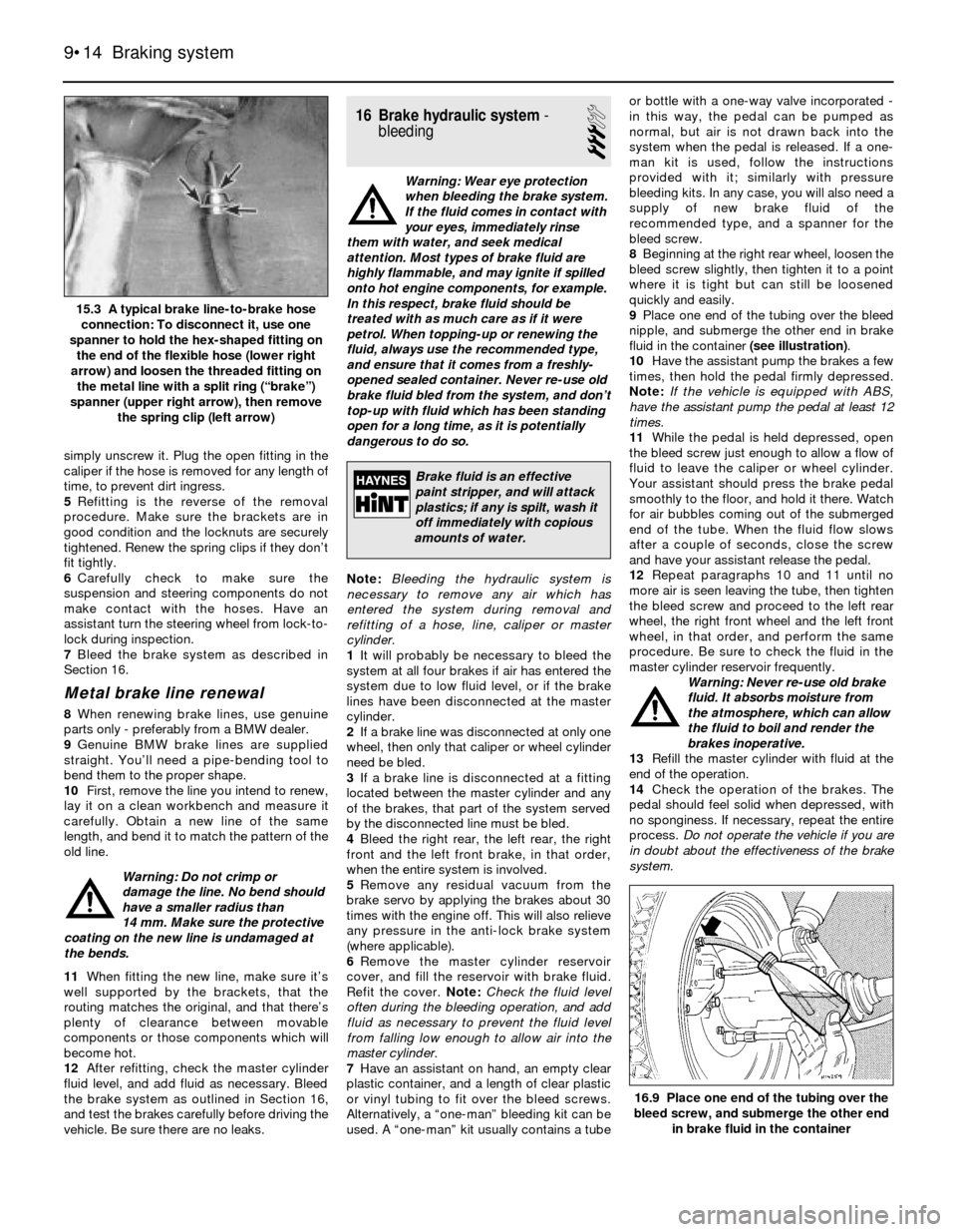
9Place one end of the tubing over the bleed
nipple, and submerge the other end in brake
fluid in the container (see illustration).
10Have the assistant pump the brakes a few
times, then hold the pedal firmly depressed.
Note:If the vehicle is equipped with ABS,
have the assistant pump the pedal at least 12
times.
11While the pedal is held depressed, open
the bleed screw just enough to allow a flow of
fluid to leave the caliper or wheel cylinder.
Your assistant should press the brake pedal
smoothly to the floor, and hold it there. Watch
for air bubbles coming out of the submerged
end of the tube. When the fluid flow slows
after a couple of seconds, close the screw
and have your assistant release the pedal.
12Repeat paragraphs 10 and 11 until no
more air is seen leaving the tube, then tighten
the bleed screw and proceed to the left rear
wheel, the right front wheel and the left front
wheel, in that order, and perform the same
procedure. Be sure to check the fluid in the
master cylinder reservoir frequently.
Warning: Never re-use old brake
fluid. It absorbs moisture from
the atmosphere, which can allow
the fluid to boil and render the
brakes inoperative.
13Refill the master cylinder with fluid at the
end of the operation.
14Check the operation of the brakes. The
pedal should feel solid when depressed, with
no sponginess. If necessary, repeat the entire
process. Do not operate the vehicle if you are
in doubt about the effectiveness of the brake
system.
9•14 Braking system
16.9 Place one end of the tubing over the
bleed screw, and submerge the other end
in brake fluid in the container
15.3 A typical brake line-to-brake hose
connection: To disconnect it, use one
spanner to hold the hex-shaped fitting on
the end of the flexible hose (lower right
arrow) and loosen the threaded fitting on
the metal line with a split ring (“brake”)
spanner (upper right arrow), then remove
the spring clip (left arrow)
Brake fluid is an effective
paint stripper, and will attack
plastics; if any is spilt, wash it
off immediately with copious
amounts of water.
Page 163 of 228
7 Hinges and locks-
maintenance
1
Every six months or so, the hinges and lock
assemblies on the doors, bonnet and the boot
lid/tailgate should be given a few drops of
light oil or lock lubricant. The door or tailgate
lock strikers should also be lubricated with a
thin coat of grease, to reduce wear and
ensure free movement.
8 Fixed glass- renewal
5
Renewal of the windscreen and fixed glass
requires the use of special fast-setting
adhesive materials, and some specialised
tools and techniques. These operations
should be left to a dealer service department
or windscreen specialist.
9 Radiator grille-
removal and refitting
1
3-Series
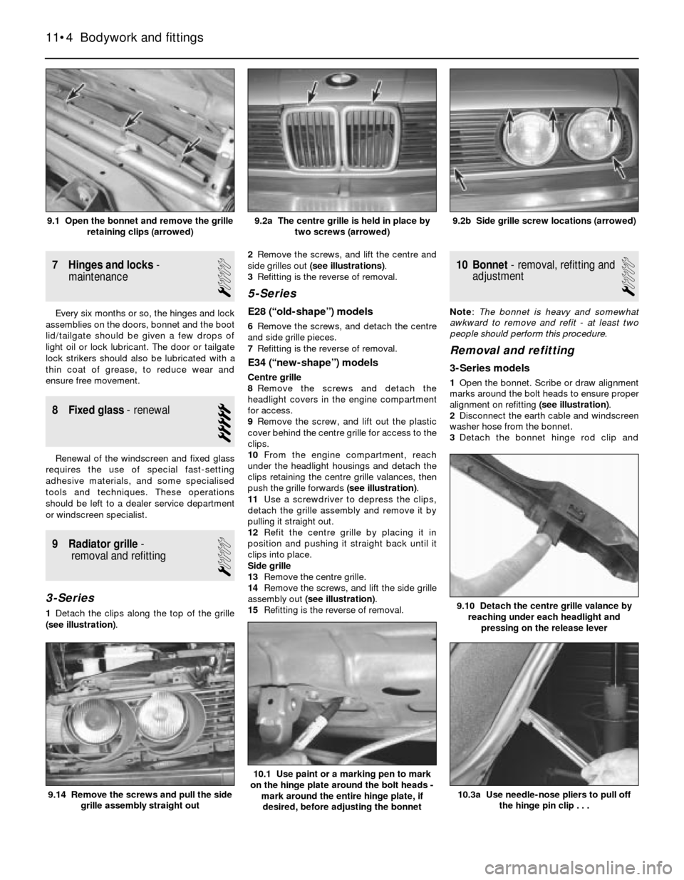
1Detach the clips along the top of the grille
(see illustration).2Remove the screws, and lift the centre and
side grilles out (see illustrations).
3Refitting is the reverse of removal.
5-Series
E28 (“old-shape”) models
6Remove the screws, and detach the centre
and side grille pieces.
7Refitting is the reverse of removal.
E34 (“new-shape”) models
Centre grille
8Remove the screws and detach the
headlight covers in the engine compartment
for access.
9Remove the screw, and lift out the plastic
cover behind the centre grille for access to the
clips.
10From the engine compartment, reach
under the headlight housings and detach the
clips retaining the centre grille valances, then
push the grille forwards (see illustration).
11Use a screwdriver to depress the clips,
detach the grille assembly and remove it by
pulling it straight out.
12Refit the centre grille by placing it in
position and pushing it straight back until it
clips into place.
Side grille
13Remove the centre grille.
14Remove the screws, and lift the side grille
assembly out (see illustration).
15Refitting is the reverse of removal.
10 Bonnet- removal, refitting and
adjustment
1
Note: The bonnet is heavy and somewhat
awkward to remove and refit - at least two
people should perform this procedure.
Removal and refitting
3-Series models
1Open the bonnet. Scribe or draw alignment
marks around the bolt heads to ensure proper
alignment on refitting (see illustration).
2Disconnect the earth cable and windscreen
washer hose from the bonnet.
3Detach the bonnet hinge rod clip and
11•4 Bodywork and fittings
10.3a Use needle-nose pliers to pull off
the hinge pin clip . . .
10.1 Use paint or a marking pen to mark
on the hinge plate around the bolt heads -
mark around the entire hinge plate, if
desired, before adjusting the bonnet
9.14 Remove the screws and pull the side
grille assembly straight out
9.10 Detach the centre grille valance by
reaching under each headlight and
pressing on the release lever
9.2b Side grille screw locations (arrowed)9.2a The centre grille is held in place by
two screws (arrowed)9.1 Open the bonnet and remove the grille
retaining clips (arrowed)
Page 175 of 228
16 Windscreen/tailgate wiper
motor- removal and refitting
2
Caution: If the radio in your
vehicle is equipped with an anti-
theft system, make sure you have
the correct activation code
before disconnecting the battery, Refer to
the information on page 0-7 at the front of
this manual before detaching the cable.
Note: If, after connecting the battery, the
wrong language appears on the instrument
panel display, refer to page 0-7 for the
language resetting procedure.
1Disconnect the battery negative cable.
Windscreen wiper motor
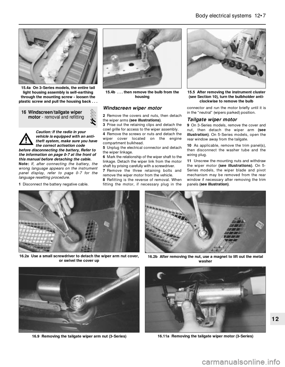
2Remove the covers and nuts, then detach
the wiper arms (see illustrations).
3Prise out the retaining clips and detach the
cowl grille for access to the wiper assembly.
4Remove the screws or nuts and detach the
wiper cover located on the engine
compartment bulkhead.
5Unplug the electrical connector and detach
the wiper linkage.
6Mark the relationship of the wiper shaft to the
linkage. Detach the wiper link from the motor
shaft by prising carefully with a screwdriver.
7Remove the three retaining bolts and
remove the wiper motor from the vehicle.
8Refitting is the reverse of removal. When
fitting the motor, if necessary plug in theconnector and run the motor briefly until it is
in the “neutral” (wipers parked) position.Tailgate wiper motor
9On 3-Series models, remove the cover and
nut, then detach the wiper arm (see
illustration). On 5-Series models, open the
rear window away from the tailgate.
10As applicable, remove the trim panel(s),
then disconnect the washer tube and the
wiring plug.
11Unscrew the mounting nuts and withdraw
the wiper motor (see illustrations). On 5-
Series models, the wiper blade and pivot
mechanism may be removed from the rear
window if necessary after removing the trim
panels (see illustration).
Body electrical systems 12•7
15.5 After removing the instrument cluster
(see Section 10), turn the bulbholder anti-
clockwise to remove the bulb15.4b . . . then remove the bulb from the
housing15.4a On 3-Series models, the entire tail
light housing assembly is self-earthing
through the mounting screw - loosen the
plastic screw and pull the housing back . . .
16.11a Removing the tailgate wiper motor (3-Series)
16.2b After removing the nut, use a magnet to lift out the metal
washer16.2a Use a small screwdriver to detach the wiper arm nut cover,
or swivel the cover up
16.9 Removing the tailgate wiper arm nut (3-Series)
12
Page 204 of 228
REF•3
REF
MOT Test Checks
Exhaust system
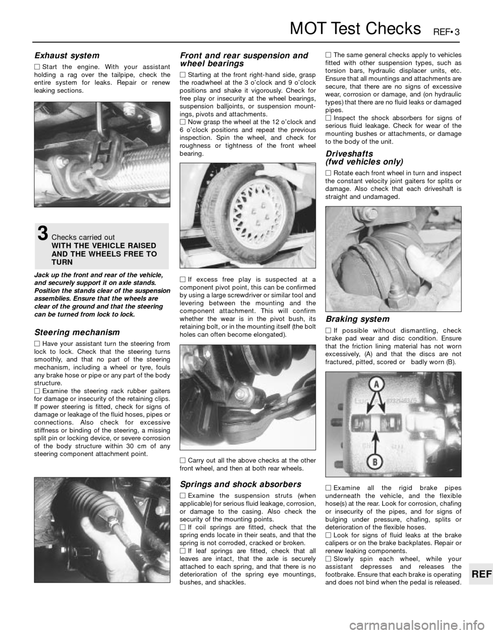
MStart the engine. With your assistant
holding a rag over the tailpipe, check the
entire system for leaks. Repair or renew
leaking sections.
Jack up the front and rear of the vehicle,
and securely support it on axle stands.
Position the stands clear of the suspension
assemblies. Ensure that the wheels are
clear of the ground and that the steering
can be turned from lock to lock.
Steering mechanism
MHave your assistant turn the steering from
lock to lock. Check that the steering turns
smoothly, and that no part of the steering
mechanism, including a wheel or tyre, fouls
any brake hose or pipe or any part of the body
structure.
MExamine the steering rack rubber gaiters
for damage or insecurity of the retaining clips.
If power steering is fitted, check for signs of
damage or leakage of the fluid hoses, pipes or
connections. Also check for excessive
stiffness or binding of the steering, a missing
split pin or locking device, or severe corrosion
of the body structure within 30 cm of any
steering component attachment point.
Front and rear suspension and
wheel bearings
MStarting at the front right-hand side, grasp
the roadwheel at the 3 o’clock and 9 o’clock
positions and shake it vigorously. Check for
free play or insecurity at the wheel bearings,
suspension balljoints, or suspension mount-
ings, pivots and attachments.
MNow grasp the wheel at the 12 o’clock and
6 o’clock positions and repeat the previous
inspection. Spin the wheel, and check for
roughness or tightness of the front wheel
bearing.
MIf excess free play is suspected at a
component pivot point, this can be confirmed
by using a large screwdriver or similar tool and
levering between the mounting and the
component attachment. This will confirm
whether the wear is in the pivot bush, its
retaining bolt, or in the mounting itself (the bolt
holes can often become elongated).
MCarry out all the above checks at the other
front wheel, and then at both rear wheels.
Springs and shock absorbers
MExamine the suspension struts (when
applicable) for serious fluid leakage, corrosion,
or damage to the casing. Also check the
security of the mounting points.
MIf coil springs are fitted, check that the
spring ends locate in their seats, and that the
spring is not corroded, cracked or broken.
MIf leaf springs are fitted, check that all
leaves are intact, that the axle is securely
attached to each spring, and that there is no
deterioration of the spring eye mountings,
bushes, and shackles.MThe same general checks apply to vehicles
fitted with other suspension types, such as
torsion bars, hydraulic displacer units, etc.
Ensure that all mountings and attachments are
secure, that there are no signs of excessive
wear, corrosion or damage, and (on hydraulic
types) that there are no fluid leaks or damaged
pipes.
MInspect the shock absorbers for signs of
serious fluid leakage. Check for wear of the
mounting bushes or attachments, or damage
to the body of the unit.
Driveshafts
(fwd vehicles only)
MRotate each front wheel in turn and inspect
the constant velocity joint gaiters for splits or
damage. Also check that each driveshaft is
straight and undamaged.
Braking system
MIf possible without dismantling, check
brake pad wear and disc condition. Ensure
that the friction lining material has not worn
excessively, (A) and that the discs are not
fractured, pitted, scored or badly worn (B).
MExamine all the rigid brake pipes
underneath the vehicle, and the flexible
hose(s) at the rear. Look for corrosion, chafing
or insecurity of the pipes, and for signs of
bulging under pressure, chafing, splits or
deterioration of the flexible hoses.
MLook for signs of fluid leaks at the brake
calipers or on the brake backplates. Repair or
renew leaking components.
MSlowly spin each wheel, while your
assistant depresses and releases the
footbrake. Ensure that each brake is operating
and does not bind when the pedal is released.
3Checks carried out
WITH THE VEHICLE RAISED
AND THE WHEELS FREE TO
TURN
Page 205 of 228
REF•4MOT Test Checks
MExamine the handbrake mechanism,
checking for frayed or broken cables,
excessive corrosion, or wear or insecurity of
the linkage. Check that the mechanism works
on each relevant wheel, and releases fully,
without binding.
MIt is not possible to test brake efficiency
without special equipment, but a road test can
be carried out later to check that the vehicle
pulls up in a straight line.
Fuel and exhaust systems
MInspect the fuel tank (including the filler
cap), fuel pipes, hoses and unions. All
components must be secure and free from
leaks.
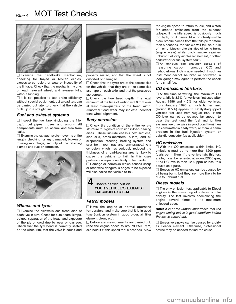
MExamine the exhaust system over its entire
length, checking for any damaged, broken or
missing mountings, security of the retaining
clamps and rust or corrosion.
Wheels and tyres
MExamine the sidewalls and tread area of
each tyre in turn. Check for cuts, tears, lumps,
bulges, separation of the tread, and exposure
of the ply or cord due to wear or damage.
Check that the tyre bead is correctly seated
on the wheel rim, that the valve is sound andproperly seated, and that the wheel is not
distorted or damaged.
MCheck that the tyres are of the correct size
for the vehicle, that they are of the same size
and type on each axle, and that the pressures
are correct.
MCheck the tyre tread depth. The legal
minimum at the time of writing is 1.6 mm over
at least three-quarters of the tread width.
Abnormal tread wear may indicate incorrect
front wheel alignment.
Body corrosion
MCheck the condition of the entire vehicle
structure for signs of corrosion in load-bearing
areas. (These include chassis box sections,
side sills, cross-members, pillars, and all
suspension, steering, braking system and
seat belt mountings and anchorages.) Any
corrosion which has seriously reduced the
thickness of a load-bearing area is likely to
cause the vehicle to fail. In this case
professional repairs are likely to be needed.
MDamage or corrosion which causes sharp
or otherwise dangerous edges to be exposed
will also cause the vehicle to fail.
Petrol models
MHave the engine at normal operating
temperature, and make sure that it is in good
tune (ignition system in good order, air filter
element clean, etc).
MBefore any measurements are carried out,
raise the engine speed to around 2500 rpm,
and hold it at this speed for 20 seconds. Allowthe engine speed to return to idle, and watch
for smoke emissions from the exhaust
tailpipe. If the idle speed is obviously much
too high, or if dense blue or clearly-visible
black smoke comes from the tailpipe for more
than 5 seconds, the vehicle will fail. As a rule
of thumb, blue smoke signifies oil being burnt
(engine wear) while black smoke signifies
unburnt fuel (dirty air cleaner element, or other
carburettor or fuel system fault).
MAn exhaust gas analyser capable of
measuring carbon monoxide (CO) and
hydrocarbons (HC) is now needed. If such an
instrument cannot be hired or borrowed, a
local garage may agree to perform the check
for a small fee.
CO emissions (mixture)
MAt the time of writing, the maximum CO
level at idle is 3.5% for vehicles first used after
August 1986 and 4.5% for older vehicles.
From January 1996 a much tighter limit
(around 0.5%) applies to catalyst-equipped
vehicles first used from August 1992. If the
CO level cannot be reduced far enough to
pass the test (and the fuel and ignition
systems are otherwise in good condition) then
the carburettor is badly worn, or there is some
problem in the fuel injection system or
catalytic converter (as applicable).
HC emissionsMWith the CO emissions within limits, HC
emissions must be no more than 1200 ppm
(parts per million). If the vehicle fails this test
at idle, it can be re-tested at around 2000 rpm;
if the HC level is then 1200 ppm or less, this
counts as a pass.
MExcessive HC emissions can be caused by
oil being burnt, but they are more likely to be
due to unburnt fuel.
Diesel models
MThe only emission test applicable to Diesel
engines is the measuring of exhaust smoke
density. The test involves accelerating the
engine several times to its maximum
unloaded speed.
Note: It is of the utmost importance that the
engine timing belt is in good condition before
the test is carried out.
M
Excessive smoke can be caused by a dirty
air cleaner element. Otherwise, professional
advice may be needed to find the cause.
4Checks carried out on
YOUR VEHICLE’S EXHAUST
EMISSION SYSTEM
Page 223 of 228
REF•23
REF
Glossary of Technical Terms
JJump startStarting the engine of a vehicle
with a discharged or weak battery by
attaching jump leads from the weak battery to
a charged or helper battery.
LLoad Sensing Proportioning Valve (LSPV)A
brake hydraulic system control valve that
works like a proportioning valve, but also
takes into consideration the amount of weight
carried by the rear axle.
LocknutA nut used to lock an adjustment
nut, or other threaded component, in place.
For example, a locknut is employed to keep
the adjusting nut on the rocker arm in
position.
LockwasherA form of washer designed to
prevent an attaching nut from working loose.
MMacPherson strutA type of front
suspension system devised by Earle
MacPherson at Ford of England. In its original
form, a simple lateral link with the anti-roll bar
creates the lower control arm. A long strut - an
integral coil spring and shock absorber - is
mounted between the body and the steering
knuckle. Many modern so-called MacPherson
strut systems use a conventional lower A-arm
and don’t rely on the anti-roll bar for location.
MultimeterAn electrical test instrument with
the capability to measure voltage, current and
resistance.
NNOxOxides of Nitrogen. A common toxic
pollutant emitted by petrol and diesel engines
at higher temperatures.
OOhmThe unit of electrical resistance. One
volt applied to a resistance of one ohm will
produce a current of one amp.
OhmmeterAn instrument for measuring
electrical resistance.
O-ringA type of sealing ring made of a
special rubber-like material; in use, the O-ring
is compressed into a groove to provide the
sealing action.Overhead cam (ohc) engineAn engine with
the camshaft(s) located on top of the cylinder
head(s).
Overhead valve (ohv) engineAn engine with
the valves located in the cylinder head, but
with the camshaft located in the engine block.
Oxygen sensorA device installed in the
engine exhaust manifold, which senses the
oxygen content in the exhaust and converts
this information into an electric current. Also
called a Lambda sensor.
PPhillips screwA type of screw head having a
cross instead of a slot for a corresponding
type of screwdriver.
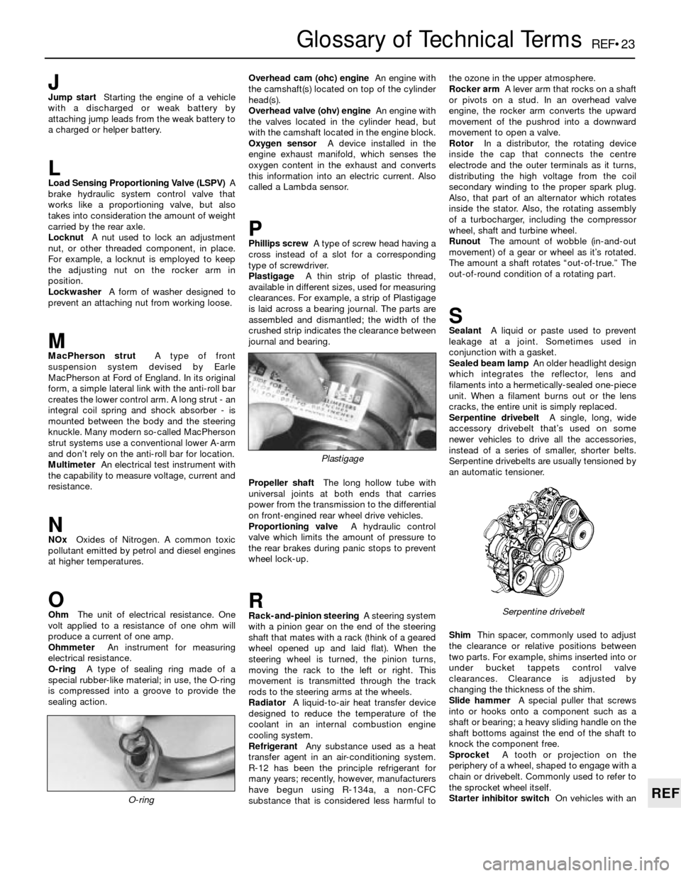
PlastigageA thin strip of plastic thread,
available in different sizes, used for measuring
clearances. For example, a strip of Plastigage
is laid across a bearing journal. The parts are
assembled and dismantled; the width of the
crushed strip indicates the clearance between
journal and bearing.
Propeller shaftThe long hollow tube with
universal joints at both ends that carries
power from the transmission to the differential
on front-engined rear wheel drive vehicles.
Proportioning valveA hydraulic control
valve which limits the amount of pressure to
the rear brakes during panic stops to prevent
wheel lock-up.
RRack-and-pinion steeringA steering system
with a pinion gear on the end of the steering
shaft that mates with a rack (think of a geared
wheel opened up and laid flat). When the
steering wheel is turned, the pinion turns,
moving the rack to the left or right. This
movement is transmitted through the track
rods to the steering arms at the wheels.
RadiatorA liquid-to-air heat transfer device
designed to reduce the temperature of the
coolant in an internal combustion engine
cooling system.
RefrigerantAny substance used as a heat
transfer agent in an air-conditioning system.
R-12 has been the principle refrigerant for
many years; recently, however, manufacturers
have begun using R-134a, a non-CFC
substance that is considered less harmful tothe ozone in the upper atmosphere.
Rocker armA lever arm that rocks on a shaft
or pivots on a stud. In an overhead valve
engine, the rocker arm converts the upward
movement of the pushrod into a downward
movement to open a valve.
RotorIn a distributor, the rotating device
inside the cap that connects the centre
electrode and the outer terminals as it turns,
distributing the high voltage from the coil
secondary winding to the proper spark plug.
Also, that part of an alternator which rotates
inside the stator. Also, the rotating assembly
of a turbocharger, including the compressor
wheel, shaft and turbine wheel.
RunoutThe amount of wobble (in-and-out
movement) of a gear or wheel as it’s rotated.
The amount a shaft rotates “out-of-true.” The
out-of-round condition of a rotating part.
SSealantA liquid or paste used to prevent
leakage at a joint. Sometimes used in
conjunction with a gasket.
Sealed beam lampAn older headlight design
which integrates the reflector, lens and
filaments into a hermetically-sealed one-piece
unit. When a filament burns out or the lens
cracks, the entire unit is simply replaced.
Serpentine drivebeltA single, long, wide
accessory drivebelt that’s used on some
newer vehicles to drive all the accessories,
instead of a series of smaller, shorter belts.
Serpentine drivebelts are usually tensioned by
an automatic tensioner.
ShimThin spacer, commonly used to adjust
the clearance or relative positions between
two parts. For example, shims inserted into or
under bucket tappets control valve
clearances. Clearance is adjusted by
changing the thickness of the shim.
Slide hammerA special puller that screws
into or hooks onto a component such as a
shaft or bearing; a heavy sliding handle on the
shaft bottoms against the end of the shaft to
knock the component free.
SprocketA tooth or projection on the
periphery of a wheel, shaped to engage with a
chain or drivebelt. Commonly used to refer to
the sprocket wheel itself.
Starter inhibitor switchOn vehicles with an
O-ring
Serpentine drivebelt
Plastigage