service BMW 3 SERIES 1987 E30 Service Manual
[x] Cancel search | Manufacturer: BMW, Model Year: 1987, Model line: 3 SERIES, Model: BMW 3 SERIES 1987 E30Pages: 228, PDF Size: 7.04 MB
Page 148 of 228
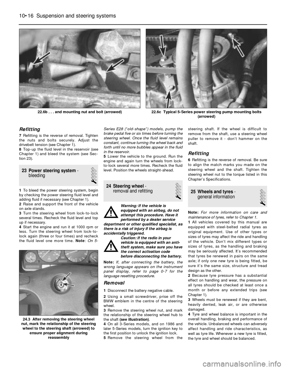
Bush inspection and renewal
8If the bush is cracked, torn or otherwise
deteriorated, take the arm to a BMW dealer
service department or an engineering works,
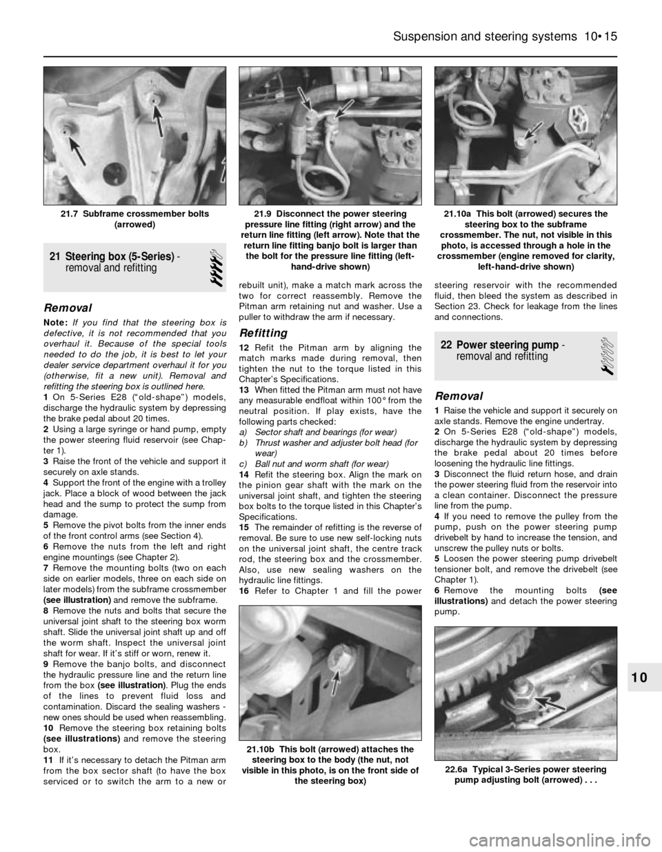
and have it pressed out and a new bush
pressed in. Bushes should always be renewed
in pairs (a new bush should be fitted in each
arm, and both bushes should have the same
manufacturer markings). If you’re fitting a new
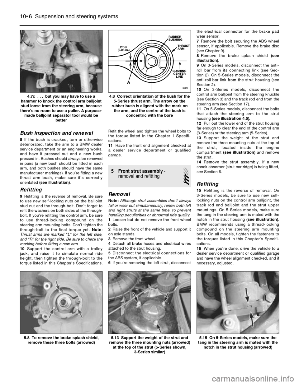
thrust arm bush, make sure it’s correctly
orientated (see illustration).
Refitting
9Refitting is the reverse of removal. Be sure
to use new self-locking nuts on the balljoint
stud nut and the through-bolt. Don’t forget to
refit the washers on both sides of the through-
bolt. If you’re refitting the control arm, be sure
to use thread-locking compound on the
steering arm mounting bolts. Don’t tighten the
through-bolt to the final torque yet. Note:
Thrust arms are marked “L” for the left side,
and “R” for the right side. Be sure to check the
marking before fitting a new arm.
10Support the control arm with a trolley
jack, and raise it to simulate normal ride
height, then tighten the through-bolt to the
torque listed in this Chapter’s Specifications.Refit the wheel and tighten the wheel bolts to
the torque listed in the Chapter 1 Specifi-
cations.
11Have the front end alignment checked at
a dealer service department or qualified
garage.
5 Front strut assembly-
removal and refitting
3
Removal
Note:Although strut assemblies don’t always
fail or wear out simultaneously, renew both left
and right struts at the same time, to prevent
handling peculiarities or abnormal ride quality.
1Loosen but do not remove the front wheel
bolts.
2Raise the front of the vehicle and support it
on axle stands.
3Remove the front wheel.
4Detach all brake hoses and electrical wires
attached to the strut housing.
5Disconnect the electrical connections for
the ABS system, if applicable.
6If you’re removing the left strut, disconnectthe electrical connector for the brake pad
wear sensor.
7Remove the bolt securing the ABS wheel
sensor, if applicable. Remove the brake disc
(see Chapter 9).
8Remove the brake splash shield (see
illustration).
9On 3-Series models, disconnect the anti-
roll bar from its connecting link (see Sec-
tion 2). On 5-Series models, disconnect the
anti-roll bar link from the strut housing (see
Section 2).
10On 3-Series models, disconnect the
control arm balljoint from the steering knuckle
(see Section 3) and the track rod end from the
steering arm (see Section 17).
11On 5-Series models, disconnect the bolts
that attach the steering arm to the strut
housing (see illustration 4.5).
12Pull out the lower end of the strut housing
far enough to clear the end of the control arm
(3-Series) or the steering arm (5-Series).
13Support the weight of the strut and
remove the three mounting nuts at the top of
the strut, located inside the engine
compartment (see illustration)and remove
the strut.
14Remove the strut assembly. If a new
shock absorber (strut cartridge) is being fitted,
see Section 6.
Refitting
15Refitting is the reverse of removal. On
3-Series models, be sure to use new self-
locking nuts on the control arm balljoint, the
track rod end balljoint and the strut upper
mountings. On 5-Series models, make sure
the tang in the steering arm is mated with the
notch in the strut housing (see illustration).
BMW recommends using a thread-locking
compound on the steering arm mounting
bolts. On all models, tighten the fasteners to
the torques listed in this Chapter’s Specifi-
cations.
16When you’re done, drive the vehicle to a
dealer service department or qualified garage
and have the wheel alignment checked, and if
necessary, adjusted.
10•6 Suspension and steering systems
5.15 On 5-Series models, make sure the
tang in the steering arm is mated with the
notch in the strut housing (arrowed)5.13 Support the weight of the strut and
remove the three mounting nuts (arrowed)
at the top of the strut (5-Series shown,
3-Series similar)5.8 To remove the brake splash shield,
remove these three bolts (arrowed)
4.8 Correct orientation of the bush for the
5-Series thrust arm. The arrow on the
rubber bush is aligned with the mark on
the arm, and the centre of the bush is
concentric with the bore4.7c . . . but you may have to use a
hammer to knock the control arm balljoint
stud loose from the steering arm, because
there’s no room to use a puller. A purpose-
made balljoint separator tool would be
better
Page 150 of 228
problem exists, a new subframe or steering
arm (5-Series) or steering knuckle (3-Series),
which is integral with the strut housing, should
be fitted as well as the new balljoint.
Renewal
Note: None of these balljoints can be serviced
or renewed individually. If one of them is worn,
a complete new arm must be fitted.
8 Front hub and wheel bearing
assembly-
removal and refitting
3
Note:Removing the front hub/bearing
assembly renders it unfit for re-use. A new
assembly will be required for refitting.
Removal
1Loosen the wheel bolts, then raise the front
of the vehicle, and support it securely on axle
stands. Remove the wheel bolts and the
wheel.
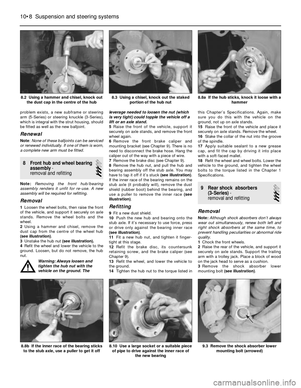
2Using a hammer and chisel, remove the
dust cap from the centre of the wheel hub
(see illustration).
3Unstake the hub nut (see illustration).
4Refit the wheel and lower the vehicle to the
ground. Loosen, but do not remove, the hub
nut.
Warning: Always loosen and
tighten the hub nut with the
vehicle on the ground. Theleverage needed to loosen the nut (which
is very tight) could topple the vehicle off a
lift or an axle stand.
5Raise the front of the vehicle, support it
securely on axle stands, and remove the front
wheel again.
6Remove the front brake caliper and
mounting bracket (see Chapter 9). There is no
need to disconnect the brake hose. Hang the
caliper out of the way with a piece of wire.
7Remove the brake disc (see Chapter 9).
8Remove the hub nut, and pull the hub and
bearing assembly off the stub axle. You may
have to tap it off if it’s stuck (see illustration).
If the inner race of the bearing remains on the
stub axle (it probably will), remove the dust
shield (rubber boot) behind the bearing, and
use a puller to remove the inner race (see
illustration).Refitting
9Fit a new dust shield.
10Push the new hub and bearing onto the
stub axle. If it’s necessary to use force, press
or drive only against the bearing inner race
(see illustration).
11Fit a new hub nut, and tighten it finger-
tight at this stage.
12Refit the brake disc, its countersunk
retaining screw, and the brake caliper (see
Chapter 9).
13Refit the wheel, and lower the vehicle to
the ground.
14Tighten the hub nut to the torque listed inthis Chapter’s Specifications. Again, make
sure you do this with the vehicle on the
ground, not up on axle stands.
15Raise the front of the vehicle and place it
securely on axle stands. Remove the wheel.
16Stake the collar of the nut into the groove
of the spindle.
17Apply suitable sealant to a new grease
cap, and fit the cap by driving it into place
with a soft-faced mallet.
18Refit the wheel and wheel bolts. Lower the
vehicle to the ground, and tighten the wheel
bolts to the torque listed in the Chapter 1
Specifications.
9 Rear shock absorbers
(3-Series)-
removal and refitting
3
Removal
Note:Although shock absorbers don’t always
wear out simultaneously, renew both left and
right shock absorbers at the same time, to
prevent handling peculiarities or abnormal ride
quality.
1Chock the front wheels.
2Raise the rear of the vehicle, and support it
securely on axle stands. Support the trailing
arm with a trolley jack. Place a block of wood
on the jack head to serve as a cushion.
3Remove the shock absorber lower
mounting bolt (see illustration).
10•8 Suspension and steering systems
9.3 Remove the shock absorber lower
mounting bolt (arrowed)8.10 Use a large socket or a suitable piece
of pipe to drive against the inner race of
the new bearing8.8b If the inner race of the bearing sticks
to the stub axle, use a puller to get it off
8.8a If the hub sticks, knock it loose with a
hammer8.3 Using a chisel, knock out the staked
portion of the hub nut8.2 Using a hammer and chisel, knock out
the dust cap in the centre of the hub
Page 155 of 228
Where power-assistance is fitted, hydraulic
pressure (provided by an engine-driven pump)
delivers power steering fluid to the rack-and-
pinion steering gear or the recirculating-ball
steering box - this enhances steering
response and reduces steering effort.
Aside from maintaining the proper level of
power steering fluid in the system and
checking the tension of the drivebelt (see
Chapter 1, where applicable), the steering
system requires no maintenance. However,
on high-mileage vehicles, the track rod end
balljoints, the universal joints on either end of
the universal joint shaft, and the rubber
coupling between the steering column and the
universal joint shaft will wear, develop
excessive play, and cause the steering to feel
somewhat loose. At this point, you’ll have to
renew these items; they can’t be serviced.
Before you conclude that the steering
system needs work, however, always check
the tyres (see Section 25) and tyre pressures
(see Chapter 1). Also inspect the bearings in
the strut upper mounts (see Section 5), the
front hub bearings (see Section 8) and other
suspension parts, which may also be
contributing to an imprecise steering feel.
17 Track rod ends-
removal and refitting
4
1Loosen but do not remove the wheel bolts,
then raise the front of the vehicle and secure it
on axle stands. Remove the front wheel.
3-Series models
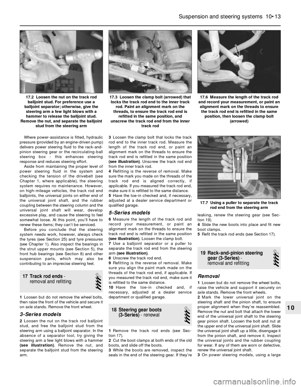
2Loosen the nut on the track rod balljoint
stud, and free the balljoint stud from the
steering arm using a balljoint separator. In the
absence of a separator tool, try giving the
steering arm a few light blows with a hammer
(see illustration). Remove the nut, and
separate the balljoint stud from the steering
arm.3Loosen the clamp bolt that locks the track
rod end to the inner track rod. Measure the
length of the track rod end, or paint an
alignment mark on the threads to ensure the
track rod end is refitted in the same position
(see illustration). Unscrew the track rod end
from the inner track rod.
4Refitting is the reverse of removal. Make
sure the mark you made on the threads of the
track rod end is aligned correctly, if
applicable. If you measured the track rod end,
make sure it is refitted to the same distance.
5Have the toe-in checked and, if necessary,
adjusted at a dealer service department or
qualified garage.
5-Series models
6Measure the length of the track rod and
record your measurement, or paint an
alignment mark on the threads to ensure the
track rod end is refitted in the same position
(see illustration). Loosen the clamp bolt.
7Use a balljoint separator or a puller to
separate the track rod end from the steering
arm (see illustration).
8Unscrew the track rod end.
9Refitting is the reverse of removal. Make
sure you align the paint mark made on the
threads of the track rod end, if applicable. If
you measured the track rod end, make sure it
is refitted to the same distance.
10Have the toe-in checked and, if
necessary, adjusted at a dealer service
department or qualified garage.
18 Steering gear boots
(3-Series)- renewal
4
1Remove the track rod ends (see Sec-
tion 17).
2Cut the boot clamps at both ends of the old
boots, and slide off the boots.
3While the boots are removed, inspect the
seals in the end of the steering gear. If they’releaking, renew the steering gear (see Sec-
tion 19).
4Slide the new boots into place and fit new
boot clamps.
5Refit the track rod ends (see Section 17).
19 Rack-and-pinion steering
gear (3-Series)-
removal and refitting
4
Removal
1Loosen but do not remove the wheel bolts,
raise the vehicle and support it securely on
axle stands. Remove the front wheels.
2Mark the lower universal joint on the
steering shaft and the pinion shaft, to ensure
proper alignment when they’re reassembled.
Remove the nut and bolt that attach the lower
end of the universal joint shaft to the steering
gear pinion shaft. Loosen the bolt and nut at
the upper end of the universal joint shaft. Slide
the universal joint shaft up a little, disengage it
from the pinion shaft, and remove it. Inspect
the universal joints and the rubber coupling
for wear. If any of them are worn or defective,
renew the universal joint shaft.
3On power steering models, using a large
Suspension and steering systems 10•13
17.6 Measure the length of the track rod
and record your measurement, or paint an
alignment mark on the threads to ensure
the track rod end is refitted in the same
position, then loosen the clamp bolt
(arrowed)17.3 Loosen the clamp bolt (arrowed) that
locks the track rod end to the inner track
rod. Paint an alignment mark on the
threads, to ensure the track rod end is
refitted in the same position, and
unscrew the track rod end from the inner
track rod17.2 Loosen the nut on the track rod
balljoint stud. For preference use a
balljoint separator; otherwise, give the
steering arm a few light blows with a
hammer to release the balljoint stud.
Remove the nut, and separate the balljoint
stud from the steering arm
17.7 Using a puller to separate the track
rod end from the steering arm
10
Page 156 of 228
syringe or hand pump, empty the power
steering fluid reservoir.
4On power steering models, remove the
banjo bolts and disconnect the power
steering pressure and return lines from the
steering gear. Place a container under the
lines to catch spilled fluid. Plug the lines to
prevent excessive fluid loss and
contamination. Discard the sealing washers
(new ones should be used when
reassembling).
5Disconnect the track rod ends from the
steering arms (see Section 17).
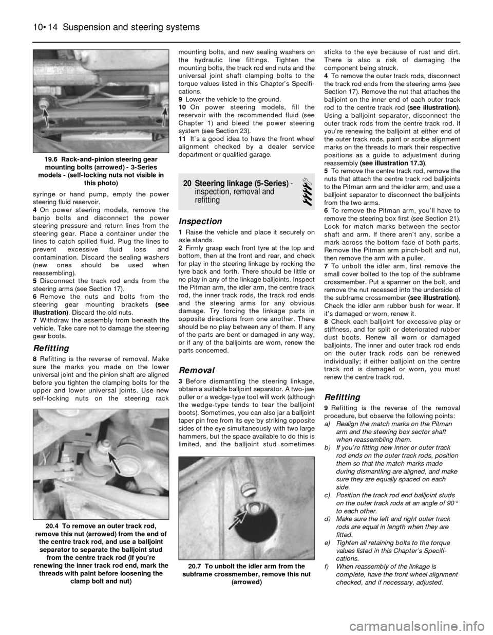
6Remove the nuts and bolts from the
steering gear mounting brackets (see
illustration). Discard the old nuts.
7Withdraw the assembly from beneath the
vehicle. Take care not to damage the steering
gear boots.
Refitting
8Refitting is the reverse of removal. Make
sure the marks you made on the lower
universal joint and the pinion shaft are aligned
before you tighten the clamping bolts for the
upper and lower universal joints. Use new
self-locking nuts on the steering rackmounting bolts, and new sealing washers on
the hydraulic line fittings. Tighten the
mounting bolts, the track rod end nuts and the
universal joint shaft clamping bolts to the
torque values listed in this Chapter’s Specifi-
cations.
9Lower the vehicle to the ground.
10On power steering models, fill the
reservoir with the recommended fluid (see
Chapter 1) and bleed the power steering
system (see Section 23).
11It’s a good idea to have the front wheel
alignment checked by a dealer service
department or qualified garage.
20 Steering linkage (5-Series)-
inspection, removal and
refitting
4
Inspection
1Raise the vehicle and place it securely on
axle stands.
2Firmly grasp each front tyre at the top and
bottom, then at the front and rear, and check
for play in the steering linkage by rocking the
tyre back and forth. There should be little or
no play in any of the linkage balljoints. Inspect
the Pitman arm, the idler arm, the centre track
rod, the inner track rods, the track rod ends
and the steering arms for any obvious
damage. Try forcing the linkage parts in
opposite directions from one another. There
should be no play between any of them. If any
of the parts are bent or damaged in any way,
or if any of the balljoints are worn, renew the
parts concerned.
Removal
3Before dismantling the steering linkage,
obtain a suitable balljoint separator. A two-jaw
puller or a wedge-type tool will work (although
the wedge-type tends to tear the balljoint
boots). Sometimes, you can also jar a balljoint
taper pin free from its eye by striking opposite
sides of the eye simultaneously with two large
hammers, but the space available to do this is
limited, and the balljoint stud sometimessticks to the eye because of rust and dirt.
There is also a risk of damaging the
component being struck.
4To remove the outer track rods, disconnect
the track rod ends from the steering arms (see
Section 17). Remove the nut that attaches the
balljoint on the inner end of each outer track
rod to the centre track rod (see illustration).
Using a balljoint separator, disconnect the
outer track rods from the centre track rod. If
you’re renewing the balljoint at either end of
the outer track rods, paint or scribe alignment
marks on the threads to mark their respective
positions as a guide to adjustment during
reassembly (see illustration 17.3).
5To remove the centre track rod, remove the
nuts that attach the centre track rod balljoints
to the Pitman arm and the idler arm, and use a
balljoint separator to disconnect the balljoints
from the two arms.
6To remove the Pitman arm, you’ll have to
remove the steering box first (see Section 21).
Look for match marks between the sector
shaft and arm. If there aren’t any, scribe a
mark across the bottom face of both parts.
Remove the Pitman arm pinch-bolt and nut,
then remove the arm with a puller.
7To unbolt the idler arm, first remove the
small cover bolted to the top of the subframe
crossmember. Put a spanner on the bolt, and
remove the nut recessed into the underside of
the subframe crossmember (see illustration).
Check the idler arm rubber bush for wear. If
it’s damaged or worn, renew it.
8Check each balljoint for excessive play or
stiffness, and for split or deteriorated rubber
dust boots. Renew all worn or damaged
balljoints. The inner and outer track rod ends
on the outer track rods can be renewed
individually; if either balljoint on the centre
track rod is damaged or worn, you must
renew the centre track rod.
Refitting
9Refitting is the reverse of the removal
procedure, but observe the following points:
a) Realign the match marks on the Pitman
arm and the steering box sector shaft
when reassembling them.
b) If you’re fitting new inner or outer track
rod ends on the outer track rods, position
them so that the match marks made
during dismantling are aligned, and make
sure they are equally spaced on each
side.
c) Position the track rod end balljoint studs
on the outer track rods at an angle of 90°
to each other.
d) Make sure the left and right outer track
rods are equal in length when they are
fitted.
e) Tighten all retaining bolts to the torque
values listed in this Chapter’s Specifi-
cations.
f) When reassembly of the linkage is
complete, have the front wheel alignment
checked, and if necessary, adjusted.
10•14 Suspension and steering systems
20.7 To unbolt the idler arm from the
subframe crossmember, remove this nut
(arrowed)
20.4 To remove an outer track rod,
remove this nut (arrowed) from the end of
the centre track rod, and use a balljoint
separator to separate the balljoint stud
from the centre track rod (if you’re
renewing the inner track rod end, mark the
threads with paint before loosening the
clamp bolt and nut)
19.6 Rack-and-pinion steering gear
mounting bolts (arrowed) - 3-Series
models - (self-locking nuts not visible in
this photo)
Page 157 of 228
21 Steering box (5-Series)-
removal and refitting
4
Removal
Note:If you find that the steering box is
defective, it is not recommended that you
overhaul it. Because of the special tools
needed to do the job, it is best to let your
dealer service department overhaul it for you
(otherwise, fit a new unit). Removal and
refitting the steering box is outlined here.
1On 5-Series E28 (“old-shape”) models,
discharge the hydraulic system by depressing
the brake pedal about 20 times.
2Using a large syringe or hand pump, empty
the power steering fluid reservoir (see Chap-
ter 1).
3Raise the front of the vehicle and support it
securely on axle stands.
4Support the front of the engine with a trolley
jack. Place a block of wood between the jack
head and the sump to protect the sump from
damage.
5Remove the pivot bolts from the inner ends
of the front control arms (see Section 4).
6Remove the nuts from the left and right
engine mountings (see Chapter 2).
7Remove the mounting bolts (two on each
side on earlier models, three on each side on
later models) from the subframe crossmember
(see illustration)and remove the subframe.
8Remove the nuts and bolts that secure the
universal joint shaft to the steering box worm
shaft. Slide the universal joint shaft up and off
the worm shaft. Inspect the universal joint
shaft for wear. If it’s stiff or worn, renew it.
9Remove the banjo bolts, and disconnect
the hydraulic pressure line and the return line
from the box (see illustration). Plug the ends
of the lines to prevent fluid loss and
contamination. Discard the sealing washers -
new ones should be used when reassembling.
10Remove the steering box retaining bolts
(see illustrations)and remove the steering
box.
11If it’s necessary to detach the Pitman arm
from the box sector shaft (to have the box
serviced or to switch the arm to a new orrebuilt unit), make a match mark across the
two for correct reassembly. Remove the
Pitman arm retaining nut and washer. Use a
puller to withdraw the arm if necessary.
Refitting
12Refit the Pitman arm by aligning the
match marks made during removal, then
tighten the nut to the torque listed in this
Chapter’s Specifications.
13When fitted the Pitman arm must not have
any measurable endfloat within 100° from the
neutral position. If play exists, have the
following parts checked:
a) Sector shaft and bearings (for wear)
b) Thrust washer and adjuster bolt head (for
wear)
c) Ball nut and worm shaft (for wear)
14Refit the steering box. Align the mark on
the pinion gear shaft with the mark on the
universal joint shaft, and tighten the steering
box bolts to the torque listed in this Chapter’s
Specifications.
15The remainder of refitting is the reverse of
removal. Be sure to use new self-locking nuts
on the universal joint shaft, the centre track
rod, the steering box and the crossmember.
Also, use new sealing washers on the
hydraulic line fittings.
16Refer to Chapter 1 and fill the powersteering reservoir with the recommended
fluid, then bleed the system as described in
Section 23. Check for leakage from the lines
and connections.22 Power steering pump-
removal and refitting
1
Removal
1Raise the vehicle and support it securely on
axle stands. Remove the engine undertray.
2On 5-Series E28 (“old-shape”) models,
discharge the hydraulic system by depressing
the brake pedal about 20 times before
loosening the hydraulic line fittings.
3Disconnect the fluid return hose, and drain
the power steering fluid from the reservoir into
a clean container. Disconnect the pressure
line from the pump.
4If you need to remove the pulley from the
pump, push on the power steering pump
drivebelt by hand to increase the tension, and
unscrew the pulley nuts or bolts.
5Loosen the power steering pump drivebelt
tensioner bolt, and remove the drivebelt (see
Chapter 1).
6Remove the mounting bolts (see
illustrations)and detach the power steering
pump.
Suspension and steering systems 10•15
21.10a This bolt (arrowed) secures the
steering box to the subframe
crossmember. The nut, not visible in this
photo, is accessed through a hole in the
crossmember (engine removed for clarity,
left-hand-drive shown)21.9 Disconnect the power steering
pressure line fitting (right arrow) and the
return line fitting (left arrow). Note that the
return line fitting banjo bolt is larger than
the bolt for the pressure line fitting (left-
hand-drive shown)21.7 Subframe crossmember bolts
(arrowed)
22.6a Typical 3-Series power steering
pump adjusting bolt (arrowed) . . .
21.10b This bolt (arrowed) attaches the
steering box to the body (the nut, not
visible in this photo, is on the front side of
the steering box)
10
Page 158 of 228
Refitting
7Refitting is the reverse of removal. Tighten
the nuts and bolts securely. Adjust the
drivebelt tension (see Chapter 1).
8Top-up the fluid level in the reservoir (see
Chapter 1) and bleed the system (see Sec-
tion 23).
23 Power steering system-
bleeding
1
1To bleed the power steering system, begin
by checking the power steering fluid level and
adding fluid if necessary (see Chapter 1).
2Raise and support the front of the vehicle
on axle stands.
3Turn the steering wheel from lock-to-lock
several times. Recheck the fluid level and top
up if necessary.
4Start the engine and run it at 1000 rpm or
less. Turn the steering wheel from lock-to-
lock again (three or four times) and recheck
the fluid level one more time. Note:On 5-Series E28 (“old-shape”) models, pump the
brake pedal five or six times before turning the
steering wheel. Once the fluid level remains
constant, continue turning the wheel back and
forth until no more bubbles appear in the fluid
in the reservoir.
5Lower the vehicle to the ground. Run the
engine and again turn the wheels from lock-
to-lock several more times. Recheck the fluid
level. Position the wheels straight-ahead.24 Steering wheel-
removal and refitting
1
Warning: If the vehicle is
equipped with an airbag, do not
attempt this procedure. Have it
performed by a dealer service
department or other qualified specialist, as
there is a risk of injury if the airbag is
accidentally triggered.
Caution: If the radio in your
vehicle is equipped with an anti-
theft system, make sure you have
the correct activation code
before disconnecting the battery.
Note: If, after connecting the battery, the
wrong language appears on the instrument
panel display, refer to page 0-7 for the
language resetting procedure.
Removal
1Disconnect the battery negative cable.
2Using a small screwdriver, prise off the
BMW emblem in the centre of the steering
wheel.
3Remove the steering wheel nut, and mark
the relationship of the steering wheel hub to
the shaft (see illustration).
4On all 3-Series models, and on 1986 and
later 5-Series models, turn the ignition key to
the first position to unlock the ignition lock.
5Remove the steering wheel from thesteering shaft. If the wheel is difficult to
remove from the shaft, use a steering wheel
puller to remove it - don’t hammer on the
shaft.
Refitting
6Refitting is the reverse of removal. Be sure
to align the match marks you made on the
steering wheel and the shaft. Tighten the
steering wheel nut to the torque listed in this
Chapter’s Specifications.
25 Wheels and tyres-
general information
1
Note:For more information on care and
maintenance of tyres, refer to Chapter 1.
1All vehicles covered by this manual are
equipped with steel-belted radial tyres as
original equipment. Use of other types or
sizes of tyres may affect the ride and handling
of the vehicle. Don’t mix different types or
sizes of tyres, as the handling and braking
may be seriously affected. It’s recommended
that tyres be renewed in pairs on the same
axle; if only one new tyre is being fitted, be
sure it’s the same size, structure and tread
design as the other.
2Because tyre pressure has a substantial
effect on handling and wear, the pressure on
all tyres should be checked at least once a
month or before any extended trips (see
Chapter 1).
3Wheels must be renewed if they are bent,
heavily dented, leak air, or are otherwise
damaged.
4Tyre and wheel balance is important in the
overall handling, braking and performance of
the vehicle. Unbalanced wheels can adversely
affect handling and ride characteristics, as
well as tyre life. Whenever a new tyre is fitted,
the tyre and wheel should be balanced.
10•16 Suspension and steering systems
24.3 After removing the steering wheel
nut, mark the relationship of the steering
wheel to the steering shaft (arrowed) to
ensure proper alignment during
reassembly
22.6c Typical 5-Series power steering pump mounting bolts
(arrowed)22.6b . . . and mounting nut and bolt (arrowed)
Page 163 of 228
7 Hinges and locks-
maintenance
1
Every six months or so, the hinges and lock
assemblies on the doors, bonnet and the boot
lid/tailgate should be given a few drops of
light oil or lock lubricant. The door or tailgate
lock strikers should also be lubricated with a
thin coat of grease, to reduce wear and
ensure free movement.
8 Fixed glass- renewal
5
Renewal of the windscreen and fixed glass
requires the use of special fast-setting
adhesive materials, and some specialised
tools and techniques. These operations
should be left to a dealer service department
or windscreen specialist.
9 Radiator grille-
removal and refitting
1
3-Series
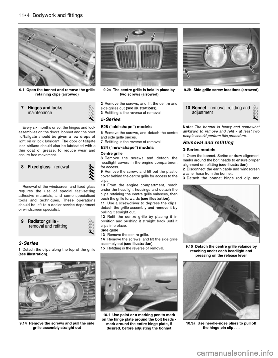
1Detach the clips along the top of the grille
(see illustration).2Remove the screws, and lift the centre and
side grilles out (see illustrations).
3Refitting is the reverse of removal.
5-Series
E28 (“old-shape”) models
6Remove the screws, and detach the centre
and side grille pieces.
7Refitting is the reverse of removal.
E34 (“new-shape”) models
Centre grille
8Remove the screws and detach the
headlight covers in the engine compartment
for access.
9Remove the screw, and lift out the plastic
cover behind the centre grille for access to the
clips.
10From the engine compartment, reach
under the headlight housings and detach the
clips retaining the centre grille valances, then
push the grille forwards (see illustration).
11Use a screwdriver to depress the clips,
detach the grille assembly and remove it by
pulling it straight out.
12Refit the centre grille by placing it in
position and pushing it straight back until it
clips into place.
Side grille
13Remove the centre grille.
14Remove the screws, and lift the side grille
assembly out (see illustration).
15Refitting is the reverse of removal.
10 Bonnet- removal, refitting and
adjustment
1
Note: The bonnet is heavy and somewhat
awkward to remove and refit - at least two
people should perform this procedure.
Removal and refitting
3-Series models
1Open the bonnet. Scribe or draw alignment
marks around the bolt heads to ensure proper
alignment on refitting (see illustration).
2Disconnect the earth cable and windscreen
washer hose from the bonnet.
3Detach the bonnet hinge rod clip and
11•4 Bodywork and fittings
10.3a Use needle-nose pliers to pull off
the hinge pin clip . . .
10.1 Use paint or a marking pen to mark
on the hinge plate around the bolt heads -
mark around the entire hinge plate, if
desired, before adjusting the bonnet
9.14 Remove the screws and pull the side
grille assembly straight out
9.10 Detach the centre grille valance by
reaching under each headlight and
pressing on the release lever
9.2b Side grille screw locations (arrowed)9.2a The centre grille is held in place by
two screws (arrowed)9.1 Open the bonnet and remove the grille
retaining clips (arrowed)
Page 169 of 228
12
Chapter 12 Body electrical systems
Bulb renewal . . . . . . . . . . . . . . . . . . . . . . . . . . . . . . . . . . . . . . . . . . . 15
Central locking system - description and check . . . . . . . . . . . . . . . . 20
Cruise control system - description and check . . . . . . . . . . . . . . . . 19
Direction indicator/hazard warning flasher - check and renewal . . . 5
Electric windows - description and check . . . . . . . . . . . . . . . . . . . . 21
Electrical system fault finding - general information . . . . . . . . . . . . . 2
Fuses - general information . . . . . . . . . . . . . . . . . . . . . . . . . . . . . . . 3
General information . . . . . . . . . . . . . . . . . . . . . . . . . . . . . . . . . . . . . . 1
Headlight housing - removal and refitting . . . . . . . . . . . . . . . . . . . . . 14
Headlights - adjustment . . . . . . . . . . . . . . . . . . . . . . . . . . . . . . . . . . 13
Headlights - bulb renewal . . . . . . . . . . . . . . . . . . . . . . . . . . . . . . . . . 12Heated rear window - check and repair . . . . . . . . . . . . . . . . . . . . . . 17
Ignition switch - removal and refitting . . . . . . . . . . . . . . . . . . . . . . . . 7
Instrument cluster - removal and refitting . . . . . . . . . . . . . . . . . . . . . 10
Radio - removal and refitting . . . . . . . . . . . . . . . . . . . . . . . . . . . . . . . 8
Radio aerial - removal and refitting . . . . . . . . . . . . . . . . . . . . . . . . . . 9
Relays - general information . . . . . . . . . . . . . . . . . . . . . . . . . . . . . . . 4
Service Indicator (SI) board - general information . . . . . . . . . . . . . . 11
Steering column switches - removal and refitting . . . . . . . . . . . . . . . 6
Supplemental Restraint System (SRS) - general information . . . . . . 18
Windscreen/tailgate wiper motor - removal and refitting . . . . . . . . . 16
Wiring diagrams - general information . . . . . . . . . . . . . . . . . . . . . . . 22
12•1
Easy,suitable for
novice with little
experienceFairly easy,suitable
for beginner with
some experienceFairly difficult,
suitable for competent
DIY mechanic
Difficult,suitable for
experienced DIY
mechanicVery difficult,
suitable for expert
DIY or professional
Degrees of difficulty Contents
1 General information
The chassis electrical system of this vehicle
is of 12-volt, negative earth type. Power for
the lights and all electrical accessories is
supplied by a lead/acid-type battery, which is
charged by the alternator.
This Chapter covers repair and service
procedures for various chassis (non-engine
related) electrical components. For
information regarding the engine electrical
system components (battery, alternator,
distributor and starter motor), see Chapter 5.
Warning: To prevent electrical
short-circuits, fires and injury,
always disconnect the battery
negative terminal before
checking, repairing or renewing electrical
components.
Caution: If the radio in your
vehicle is equipped with an anti-
theft system, make sure you have
the correct activation code
before disconnecting the battery, Refer to
the information on page 0-7 at the front of
this manual before detaching the cable.
Note: If, after connecting the battery, the
wrong language appears on the instrument
panel display, refer to page 0-7 for the
language resetting procedure.
2 Electrical system fault
finding- general information
2
A typical electrical circuit consists of an
electrical component, any switches, relays,
motors, fuses, fusible links or circuit breakers,
etc related to that component, and the wiring
and connectors that link the components to
both the battery and the chassis. To help you
pinpoint an electrical circuit problem, wiring
diagrams are included at the end of this book.
Before tackling any troublesome electrical
circuit, first study the appropriate wiring
diagrams to get a complete understanding of
what makes up that individual circuit.
Troublespots, for instance, can often be
isolated by noting if other components related
to that circuit are routed through the same
fuse and earth connections.
Electrical problems usually stem from
simple causes such as loose or corroded
connectors, a blown fuse, a melted fusible
link, or a bad relay. Inspect all fuses, wires
and connectors in a problem circuit first.
The basic tools needed include a circuit
tester, a high-impedance digital voltmeter, a
continuity tester and a jumper wire with an in-
line circuit breaker for bypassing electrical
components. Before attempting to locate or
define a problem with electrical testinstruments, use the wiring diagrams to
decide where to make the necessary
connections.
Voltage checks
Perform a voltage check first when a circuit
is not functioning properly. Connect one lead
of a circuit tester to either the negative battery
terminal or a known good earth.
Connect the other lead to a connector in
the circuit being tested, preferably nearest to
the battery or fuse. If the bulb of the tester
lights up, voltage is present, which means that
the part of the circuit between the connector
and the battery is problem-free. Continue
checking the rest of the circuit in the same
fashion.
When you reach a point at which no voltage
is present, the problem lies between that point
and the last test point with voltage. Most of
the time, problems can be traced to a loose
connection.Note:Keep in mind that some
circuits receive voltage only when the ignition
key is turned to a certain position.
Electrical fault diagnosis is simple if you
keep in mind that all electrical circuits are
basically electricity running from the battery,
through the wires, switches, relays, fuses and
fusible links to each electrical component
(light bulb, motor, etc) and then to earth, from
where it is passed back to the battery. Any
electrical problem is an interruption in the flow
of electricity to and from the battery.
Page 170 of 228
Finding a short-circuit
One method of finding a short-circuit is to
remove the fuse and connect a test light or
voltmeter in its place. There should be no
voltage present in the circuit. Move the
electrical connectors from side-to-side while
watching the test light. If the bulb goes on,
there is a short to earth somewhere in that
area, probably where the insulation has been
rubbed through. The same test can be
performed on each component in a circuit,
even a switch.
Earth check
Perform a earth check to see whether a
component is properly earthed (passing
current back via the vehicle body). Disconnect
the battery, and connect one lead of a self-
powered test light (often known as a
continuity tester) to a known good earth.
Connect the other lead to the wire or earth
connection being tested. The bulb should
light, indicating a good earth connection. If
not, dismantle the connection, and clean all
relevant parts thoroughly. When re-making
the connection, use serrated (shakeproof)
washers if possible, and tighten all bolts, etc,
securely.
Caution: If the radio in your
vehicle is equipped with an anti-
theft system, make sure you have
the correct activation code
before disconnecting the battery, Refer to
the information on page 0-7 at the front of
this manual before detaching the cable.
Note: If, after connecting the battery, the
wrong language appears on the instrument
panel display, refer to page 0-7 for the
language resetting procedure.
Continuity check
A continuity check determines if there are
any breaks in a circuit - if it is conducting
electricity properly. With the circuit off (no
power in the circuit), a self-powered continuity
tester can be used to check the circuit.
Connect the test leads to both ends of the
circuit, and if the test light comes on, the
circuit is passing current properly. If the light
doesn’t come on, there is a break somewhere
in the circuit. The same procedure can be
used to test a switch, by connecting the
continuity tester to the power-in and power-
out sides of the switch. With the switch turned
on, the test light should come on.
Finding an open-circuit
When diagnosing for possible open-
circuits, it is often difficult to locate them by
sight, because oxidation or terminal
misalignment are hidden by the connectors.
Intermittent problems are often caused by
oxidised or loose connections. Merely
wiggling an electrical connector may correct
the open-circuit condition, albeit temporarily.
Dismantle the connector, and spray with a
water-dispersant aerosol. On simpler
connectors, it may be possible to carefullybend the connector pins inside, to improve
the metal-to-metal contact - don’t damage
the connector in the process, however.
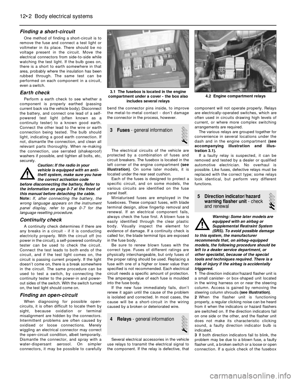
3 Fuses- general information
1
The electrical circuits of the vehicle are
protected by a combination of fuses and
circuit breakers. The fusebox is located in the
left corner of the engine compartment (see
illustration). On some later models, it is
located under the rear seat cushion.
Each of the fuses is designed to protect a
specific circuit, and on some models, the
various circuits are identified on the fuse
panel itself.
Miniaturised fuses are employed in the
fuseboxes. These compact fuses, with blade
terminal design, allow fingertip removal and
renewal. If an electrical component fails,
always check the fuse first. A blown fuse is
easily identified through the clear plastic
body. Visually inspect the element for
evidence of damage. If a continuity check is
called for, the blade terminal tips are exposed
in the fuse body.
Be sure to renew blown fuses with the
correct type. Fuses of different ratings are
physically interchangeable, but only fuses of
the proper rating should be used. Replacing a
fuse with one of a higher or lower value than
specified is not recommended. Each electrical
circuit needs a specific amount of protection.
The amperage value of each fuse is moulded
into the fuse body.
If the new fuse immediately fails, don’t
renew it again until the cause of the problem
is isolated and corrected. In most cases, the
cause will be a short-circuit in the wiring
caused by a broken or deteriorated wire.
4 Relays- general information
1
Several electrical accessories in the vehicle
use relays to transmit the electrical signal to
the component. If the relay is defective, thatcomponent will not operate properly. Relays
are electrically-operated switches, which are
often used in circuits drawing high levels of
current, or where more complex switching
arrangements are required.
The various relays are grouped together for
convenience in several locations under the
dash and in the engine compartment (see
accompanying illustration and illus-
tration 3.1).
If a faulty relay is suspected, it can be
removed and tested by a dealer or qualified
automotive electrician. No overhaul is
possible. Like fuses, defective relays must be
replaced with the correct type; some relays
look identical, but perform very different
functions.
5 Direction indicator/hazard
warning flasher unit- check
and renewal
2
Warning: Some later models are
equipped with an airbag or
Supplemental Restraint System
(SRS). To avoid possible damage
to this system, the manufacturer
recommends that, on airbag-equipped
models, the following procedure should be
left to a dealer service department, or
other specialist, because of the special
tools and techniques required. There is a
risk of injury if the airbag is accidentally
triggered.
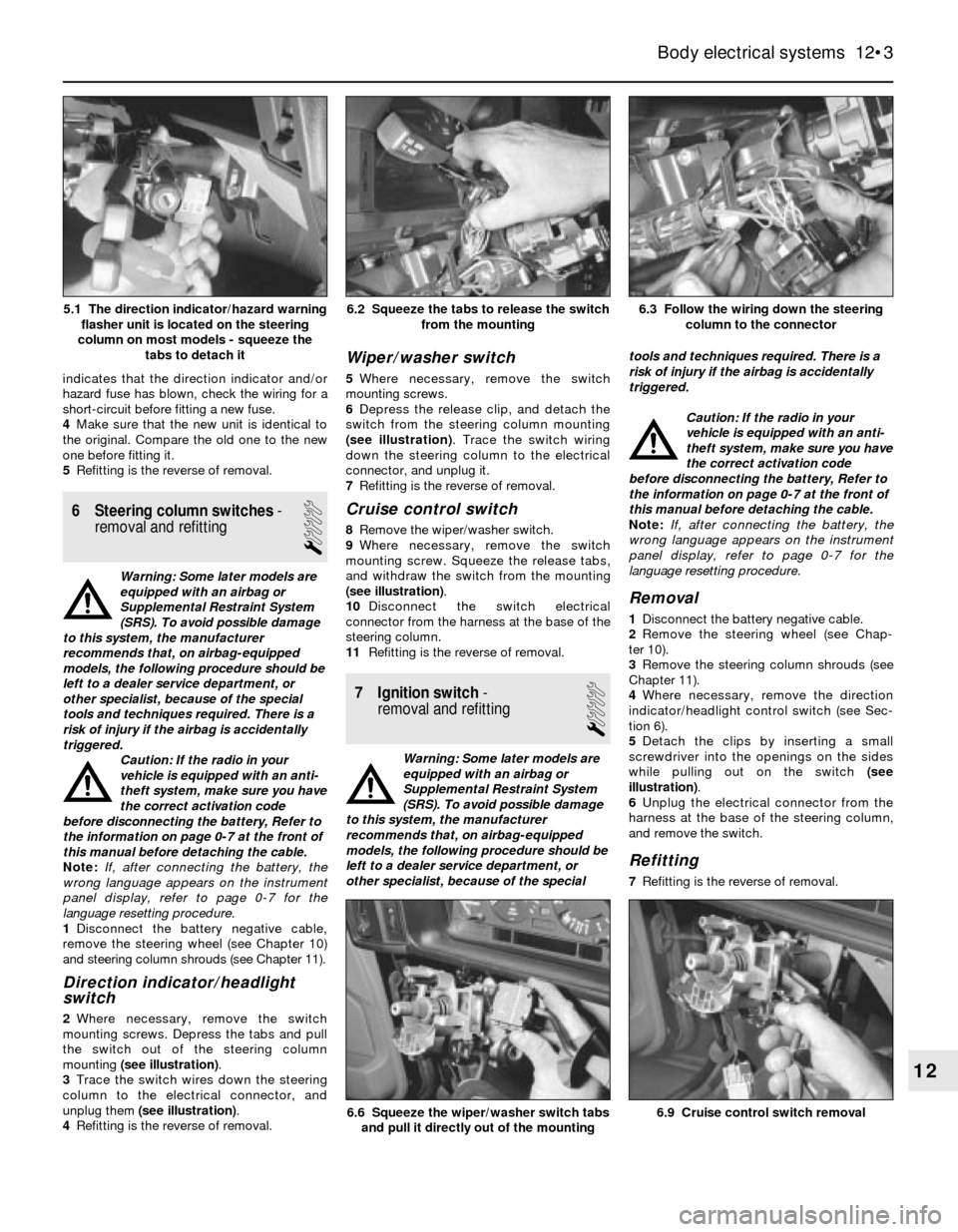
1The direction indicator/hazard flasher unit is
a small canister- or box-shaped unit located
in the wiring harness on or near the steering
column. Access is gained by removing the
steering column shrouds (see illustration).
2When the flasher unit is functioning
properly, a regular clicking noise can be heard
from it when the indicators or hazard flashers
are switched on. If the direction indicators fail
on one side or the other, and the flasher unit
does not make its characteristic clicking
sound, a faulty direction indicator bulb is
indicated.
3If both direction indicators fail to blink, the
problem may be due to a blown fuse, a faulty
flasher unit, a broken switch or a loose or open
connection. If a quick check of the fusebox
12•2 Body electrical systems
4.2 Engine compartment relays3.1 The fusebox is located in the engine
compartment under a cover - the box also
includes several relays
Page 171 of 228
indicates that the direction indicator and/or
hazard fuse has blown, check the wiring for a
short-circuit before fitting a new fuse.
4Make sure that the new unit is identical to
the original. Compare the old one to the new
one before fitting it.
5Refitting is the reverse of removal.
6 Steering column switches-
removal and refitting
1
Warning: Some later models are
equipped with an airbag or
Supplemental Restraint System
(SRS). To avoid possible damage
to this system, the manufacturer
recommends that, on airbag-equipped
models, the following procedure should be
left to a dealer service department, or
other specialist, because of the special
tools and techniques required. There is a
risk of injury if the airbag is accidentally
triggered.
Caution: If the radio in your
vehicle is equipped with an anti-
theft system, make sure you have
the correct activation code
before disconnecting the battery, Refer to
the information on page 0-7 at the front of
this manual before detaching the cable.
Note: If, after connecting the battery, the
wrong language appears on the instrument
panel display, refer to page 0-7 for the
language resetting procedure.
1Disconnect the battery negative cable,
remove the steering wheel (see Chapter 10)
and steering column shrouds (see Chapter 11).
Direction indicator/headlight
switch
2Where necessary, remove the switch
mounting screws. Depress the tabs and pull
the switch out of the steering column
mounting (see illustration).
3Trace the switch wires down the steering
column to the electrical connector, and
unplug them (see illustration).
4Refitting is the reverse of removal.
Wiper/washer switch
5Where necessary, remove the switch
mounting screws.
6Depress the release clip, and detach the
switch from the steering column mounting
(see illustration). Trace the switch wiring
down the steering column to the electrical
connector, and unplug it.
7Refitting is the reverse of removal.
Cruise control switch
8Remove the wiper/washer switch.
9Where necessary, remove the switch
mounting screw. Squeeze the release tabs,
and withdraw the switch from the mounting
(see illustration).
10Disconnect the switch electrical
connector from the harness at the base of the
steering column.
11Refitting is the reverse of removal.
7 Ignition switch-
removal and refitting
1
Warning: Some later models are
equipped with an airbag or
Supplemental Restraint System
(SRS). To avoid possible damage
to this system, the manufacturer
recommends that, on airbag-equipped
models, the following procedure should be
left to a dealer service department, or
other specialist, because of the specialtools and techniques required. There is a
risk of injury if the airbag is accidentally
triggered.
Caution: If the radio in your
vehicle is equipped with an anti-
theft system, make sure you have
the correct activation code
before disconnecting the battery, Refer to
the information on page 0-7 at the front of
this manual before detaching the cable.
Note: If, after connecting the battery, the
wrong language appears on the instrument
panel display, refer to page 0-7 for the
language resetting procedure.
Removal
1Disconnect the battery negative cable.
2Remove the steering wheel (see Chap-
ter 10).
3Remove the steering column shrouds (see
Chapter 11).
4Where necessary, remove the direction
indicator/headlight control switch (see Sec-
tion 6).
5Detach the clips by inserting a small
screwdriver into the openings on the sides
while pulling out on the switch (see
illustration).
6Unplug the electrical connector from the
harness at the base of the steering column,
and remove the switch.
Refitting
7Refitting is the reverse of removal.
Body electrical systems 12•3
6.3 Follow the wiring down the steering
column to the connector6.2 Squeeze the tabs to release the switch
from the mounting
6.9 Cruise control switch removal6.6 Squeeze the wiper/washer switch tabs
and pull it directly out of the mounting
12
5.1 The direction indicator/hazard warning
flasher unit is located on the steering
column on most models - squeeze the
tabs to detach it