fuel cap release BMW 3 SERIES 1987 E30 Workshop Manual
[x] Cancel search | Manufacturer: BMW, Model Year: 1987, Model line: 3 SERIES, Model: BMW 3 SERIES 1987 E30Pages: 228, PDF Size: 7.04 MB
Page 30 of 228

drag when the feeler gauge is moved back
and forth.
6If the gap is too large or too small, loosen
the locknut, insert a hook made from large-
diameter metal wire, and rotate the eccentric
to obtain the correct gap (see illustration).
7Once the gap has been set, hold the
eccentric in position with the hook, and
retighten the locknut securely. Recheck the
clearance - sometimes it’ll change slightly
when the locknut is tightened. If so, re-adjust
until it’s correct.
8On the M10 engine, the valves are adjusted
in the firing order, which is 1-3-4-2. After
adjusting No 1 cylinder valves, rotate the
crankshaft half a turn (180º), then check and
adjust the valves on No 3 cylinder. Repeat the
procedure on the remaining cylinders.
9On M20 and M30 engines, the valves are
adjusted following the firing order, which is
1-5-3-6-2-4. After adjusting No 1 cylinder
valves, rotate the crankshaft a third of a turn
(120º), then check and adjust the valves on No
5 cylinder. Repeat the procedure for the
remaining cylinders.
10Refit the valve cover (use a new gasket)
and tighten the mounting nuts evenly and
securely.
11Start the engine and check for oil leakage
between the valve cover and the cylinder
head.19 Throttle linkage -
check and lubrication
1
1The throttle linkage should be checked and
lubricated periodically to ensure its proper
operation.
2Check the linkage to make sure it isn’t
binding.
3Inspect the linkage joints for looseness, and
the connections for corrosion and damage,
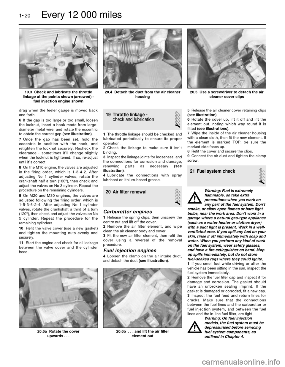
renewing parts as necessary (see
illustration).
4Lubricate the connections with spray
lubricant or lithium-based grease.
20 Air filter renewal
1
Carburettor engines
1Release the spring clips, then unscrew the
centre nut and lift off the cover.
2Remove the air filter element, and wipe
clean the air cleaner body and cover
3Fit the new air filter element, then refit the
cover using a reversal of the removal
procedure.
Fuel injection engines
4Loosen the clamp on the air intake duct,
and detach the duct (see illustration).5Release the air cleaner cover retaining clips
(see illustration).
6Rotate the cover up, lift it off and lift the
element out, noting which way round it is
fitted (see illustrations).
7Wipe the inside of the air cleaner housing
with a clean cloth, then fit the new element. If
the element is marked TOP, be sure the
marked side faces up.
8Refit the cover and secure the clips.
9Connect the air duct and tighten the clamp
screw.
21 Fuel system check
1
Warning: Fuel is extremely
flammable, so take extra
precautions when you work on
any part of the fuel system. Don’t
smoke, or allow open flames or bare light
bulbs, near the work area. Don’t work in a
garage where a natural gas-type appliance
(such as a water heater or clothes dryer)
with a pilot light is present. Work in a well-
ventilated area. If you spill any fuel on your
skin, rinse it off immediately with soap and
water. When you perform any kind of work
on the fuel system, wear safety glasses,
and have a fire extinguisher on hand. Mop
up spills immediately, but do not store
fuel-soaked rags where they could ignite.
1If you smell fuel while driving or after the
vehicle has been sitting in the sun, inspect the
fuel system immediately.
2Remove the fuel filler cap and inspect it for
damage and corrosion. The gasket should
have an unbroken sealing imprint. If the
gasket is damaged or corroded, fit a new cap.
3Inspect the fuel feed and return lines for
cracks. Make sure that the connections
between the fuel lines and the carburettor or
fuel injection system, and between the fuel
lines and the in-line fuel filter, are tight.
Warning: On fuel injection
models, the fuel system must be
depressurised before servicing
fuel system components, as
outlined in Chapter 4.
1•20
20.6b . . . and lift the air filter
element out20.6a Rotate the cover
upwards . . .
20.5 Use a screwdriver to detach the air
cleaner cover clips20.4 Detach the duct from the air cleaner
housing19.3 Check and lubricate the throttle
linkage at the points shown (arrowed) -
fuel injection engine shown
Every 12 000 miles
Page 31 of 228

4Since some components of the fuel system
- the fuel tank and some of the fuel feed and
return lines, for example - are underneath the
vehicle, they can be inspected more easily
with the vehicle raised on a hoist. If that’s not
possible, raise the vehicle and support it on
axle stands or ramps.
5With the vehicle raised and safely
supported, inspect the fuel tank and filler neck
for punctures, cracks or other damage. The
connection between the filler neck and the
tank is particularly critical. Sometimes a
rubber filler neck will leak because of loose
clamps or deteriorated rubber. Inspect all fuel
tank mounting brackets and straps, to be sure
the tank is securely attached to the vehicle.
Warning: Do not, under any
circumstances, try to repair a fuel
tank (except rubber
components). A welding torch or
any naked flame can easily cause fuel
vapours inside the tank to explode.
6Carefully check all flexible hoses and metal
lines leading away from the fuel tank. Check
for loose connections, deteriorated hoses,
crimped lines, and other damage. Repair or
renew damaged sections as necessary (see
Chapter 4).
22 Cooling system check
1
1Many major engine failures can be
attributed to cooling system problems. If the
vehicle has automatic transmission, the
engine cooling system also plays an importantrole in prolonging transmission life, because it
cools the transmission fluid.
2The engine should be cold for the cooling
system check, so perform the following
procedure before the vehicle is driven for the
day, or after it has been switched off for at
leastthree hours.
3Remove the radiator cap, doing so slowly
and taking adequate precautions against
scalding if the engine is at all warm. Clean the
cap thoroughly, inside and out, with clean
water. Also clean the filler neck on the
radiator. The presence of rust or corrosion in
the filler neck means the coolant should be
changed (see Section 29). The coolant inside
the radiator should be relatively clean and
clear. If it’s rust-coloured, drain the system
and refill with new coolant.
4Carefully check the radiator hoses and the
smaller-diameter heater hoses. Inspect each
coolant hose along its entire length, renewing
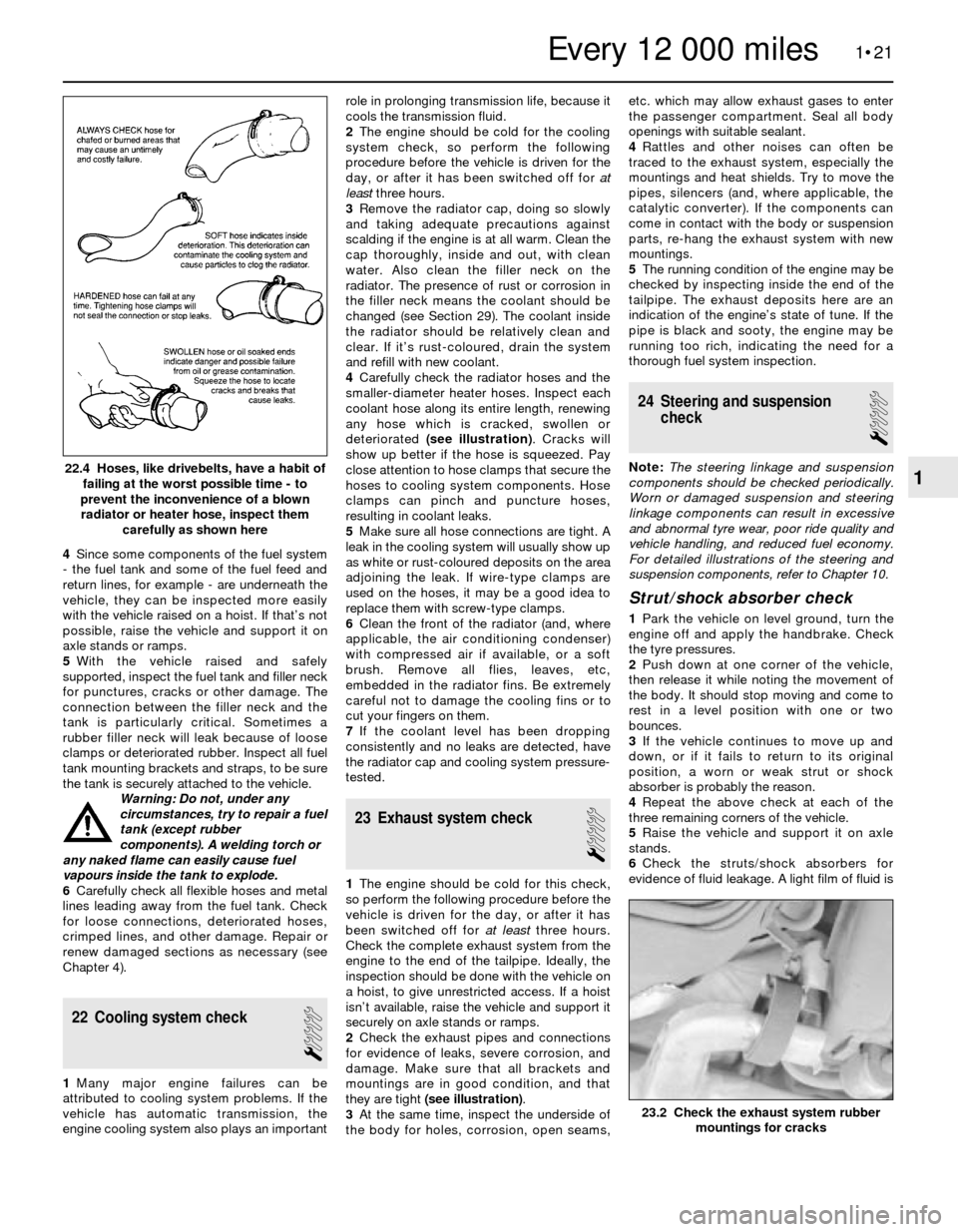
any hose which is cracked, swollen or
deteriorated (see illustration). Cracks will
show up better if the hose is squeezed. Pay
close attention to hose clamps that secure the
hoses to cooling system components. Hose
clamps can pinch and puncture hoses,
resulting in coolant leaks.
5Make sure all hose connections are tight. A
leak in the cooling system will usually show up
as white or rust-coloured deposits on the area
adjoining the leak. If wire-type clamps are
used on the hoses, it may be a good idea to
replace them with screw-type clamps.
6Clean the front of the radiator (and, where
applicable, the air conditioning condenser)
with compressed air if available, or a soft
brush. Remove all flies, leaves, etc,
embedded in the radiator fins. Be extremely
careful not to damage the cooling fins or to
cut your fingers on them.
7If the coolant level has been dropping
consistently and no leaks are detected, have
the radiator cap and cooling system pressure-
tested.
23 Exhaust system check
1
1The engine should be cold for this check,
so perform the following procedure before the
vehicle is driven for the day, or after it has
been switched off for at leastthree hours.
Check the complete exhaust system from the
engine to the end of the tailpipe. Ideally, the
inspection should be done with the vehicle on
a hoist, to give unrestricted access. If a hoist
isn’t available, raise the vehicle and support it
securely on axle stands or ramps.
2Check the exhaust pipes and connections
for evidence of leaks, severe corrosion, and
damage. Make sure that all brackets and
mountings are in good condition, and that
they are tight (see illustration).
3At the same time, inspect the underside of
the body for holes, corrosion, open seams,etc. which may allow exhaust gases to enter
the passenger compartment. Seal all body
openings with suitable sealant.
4Rattles and other noises can often be
traced to the exhaust system, especially the
mountings and heat shields. Try to move the
pipes, silencers (and, where applicable, the
catalytic converter). If the components can
come in contact with the body or suspension
parts, re-hang the exhaust system with new
mountings.
5The running condition of the engine may be
checked by inspecting inside the end of the
tailpipe. The exhaust deposits here are an
indication of the engine’s state of tune. If the
pipe is black and sooty, the engine may be
running too rich, indicating the need for a
thorough fuel system inspection.
24 Steering and suspension
check
1
Note: The steering linkage and suspension
components should be checked periodically.
Worn or damaged suspension and steering
linkage components can result in excessive
and abnormal tyre wear, poor ride quality and
vehicle handling, and reduced fuel economy.
For detailed illustrations of the steering and
suspension components, refer to Chapter 10.
Strut/shock absorber check
1Park the vehicle on level ground, turn the
engine off and apply the handbrake. Check
the tyre pressures.
2Push down at one corner of the vehicle,
then release it while noting the movement of
the body. It should stop moving and come to
rest in a level position with one or two
bounces.
3If the vehicle continues to move up and
down, or if it fails to return to its original
position, a worn or weak strut or shock
absorber is probably the reason.
4Repeat the above check at each of the
three remaining corners of the vehicle.
5Raise the vehicle and support it on axle
stands.
6Check the struts/shock absorbers for
evidence of fluid leakage. A light film of fluid is
1•21
22.4 Hoses, like drivebelts, have a habit of
failing at the worst possible time - to
prevent the inconvenience of a blown
radiator or heater hose, inspect them
carefully as shown here
23.2 Check the exhaust system rubber
mountings for cracks
1
Every 12 000 miles
Page 205 of 228

REF•4MOT Test Checks
MExamine the handbrake mechanism,
checking for frayed or broken cables,
excessive corrosion, or wear or insecurity of
the linkage. Check that the mechanism works
on each relevant wheel, and releases fully,
without binding.
MIt is not possible to test brake efficiency
without special equipment, but a road test can
be carried out later to check that the vehicle
pulls up in a straight line.
Fuel and exhaust systems
MInspect the fuel tank (including the filler
cap), fuel pipes, hoses and unions. All
components must be secure and free from
leaks.
MExamine the exhaust system over its entire
length, checking for any damaged, broken or
missing mountings, security of the retaining
clamps and rust or corrosion.
Wheels and tyres
MExamine the sidewalls and tread area of
each tyre in turn. Check for cuts, tears, lumps,
bulges, separation of the tread, and exposure
of the ply or cord due to wear or damage.
Check that the tyre bead is correctly seated
on the wheel rim, that the valve is sound andproperly seated, and that the wheel is not
distorted or damaged.
MCheck that the tyres are of the correct size
for the vehicle, that they are of the same size
and type on each axle, and that the pressures
are correct.
MCheck the tyre tread depth. The legal
minimum at the time of writing is 1.6 mm over
at least three-quarters of the tread width.
Abnormal tread wear may indicate incorrect
front wheel alignment.
Body corrosion
MCheck the condition of the entire vehicle
structure for signs of corrosion in load-bearing
areas. (These include chassis box sections,
side sills, cross-members, pillars, and all
suspension, steering, braking system and
seat belt mountings and anchorages.) Any
corrosion which has seriously reduced the
thickness of a load-bearing area is likely to
cause the vehicle to fail. In this case
professional repairs are likely to be needed.
MDamage or corrosion which causes sharp
or otherwise dangerous edges to be exposed
will also cause the vehicle to fail.
Petrol models
MHave the engine at normal operating
temperature, and make sure that it is in good
tune (ignition system in good order, air filter
element clean, etc).
MBefore any measurements are carried out,
raise the engine speed to around 2500 rpm,
and hold it at this speed for 20 seconds. Allowthe engine speed to return to idle, and watch
for smoke emissions from the exhaust
tailpipe. If the idle speed is obviously much
too high, or if dense blue or clearly-visible
black smoke comes from the tailpipe for more
than 5 seconds, the vehicle will fail. As a rule
of thumb, blue smoke signifies oil being burnt
(engine wear) while black smoke signifies
unburnt fuel (dirty air cleaner element, or other
carburettor or fuel system fault).
MAn exhaust gas analyser capable of
measuring carbon monoxide (CO) and
hydrocarbons (HC) is now needed. If such an
instrument cannot be hired or borrowed, a
local garage may agree to perform the check
for a small fee.
CO emissions (mixture)
MAt the time of writing, the maximum CO
level at idle is 3.5% for vehicles first used after
August 1986 and 4.5% for older vehicles.
From January 1996 a much tighter limit
(around 0.5%) applies to catalyst-equipped
vehicles first used from August 1992. If the
CO level cannot be reduced far enough to
pass the test (and the fuel and ignition
systems are otherwise in good condition) then
the carburettor is badly worn, or there is some
problem in the fuel injection system or
catalytic converter (as applicable).
HC emissionsMWith the CO emissions within limits, HC
emissions must be no more than 1200 ppm
(parts per million). If the vehicle fails this test
at idle, it can be re-tested at around 2000 rpm;
if the HC level is then 1200 ppm or less, this
counts as a pass.
MExcessive HC emissions can be caused by
oil being burnt, but they are more likely to be
due to unburnt fuel.
Diesel models
MThe only emission test applicable to Diesel
engines is the measuring of exhaust smoke
density. The test involves accelerating the
engine several times to its maximum
unloaded speed.
Note: It is of the utmost importance that the
engine timing belt is in good condition before
the test is carried out.
M
Excessive smoke can be caused by a dirty
air cleaner element. Otherwise, professional
advice may be needed to find the cause.
4Checks carried out on
YOUR VEHICLE’S EXHAUST
EMISSION SYSTEM
Page 213 of 228

REF•12Fault Finding
Fuel system
Excessive fuel consumption
m mDirty or clogged air filter element (Chapter 1).
m mIgnition timing incorrect (Chapter 5).
m mEmissions system not functioning properly (Chapter 6).
m mFuel injection internal parts or carburettor jets excessively worn or
damaged (Chapter 4).
m mLow tyre pressure or incorrect tyre size (Chapter 1).
m mUnsympathetic driving style, or unfavourable conditions.
Fuel leakage and/or fuel odour
Warning: Don’t drive the vehicle if a fuel leak is
suspected. Leaking fuel in the engine compartment
could catch fire.
m mLeak in a fuel feed or vent line (Chapter 4).
m mTank overfilled.
m mFuel injector or carburettor parts excessively worn, or fuel system
gaskets leaking (Chapter 4).
Cooling system
Overheating
m mInsufficient coolant in system (Chapter 1).
m mWater pump drivebelt defective or out of adjustment (Chapter 1).
m mRadiator matrix blocked, or grille restricted (Chapter 3).
m mThermostat faulty (Chapter 3).
m mRadiator cap not maintaining proper pressure (Chapter 3).
m mIgnition timing incorrect (Chapter 5).
Overcooling
m
mFaulty thermostat (Chapter 3).
External coolant leakage
m
mDeteriorated/damaged hoses; loose clamps (Chapters 1 and 3).
m mWater pump seal defective (Chapters 1 and 3).
m mLeakage from radiator matrix, heater matrix or header tank
(Chapter 3).
m mRadiator/engine block drain plugs or water jacket core plugs
leaking (Chapters 2 and 3).
Internal coolant leakage
m mLeaking cylinder head gasket (Chapter 2).
m mCracked cylinder bore or cylinder head (Chapter 2).
Coolant loss
m
mToo much coolant in system (Chapter 1).
m mCoolant boiling away because of overheating (see above).
m mInternal or external leakage (see above).
m mFaulty radiator cap (Chapter 3).
Poor coolant circulation
m
mInoperative water pump (Chapter 3).
m mRestriction in cooling system (Chapters 1 and 3).
m mWater pump drivebelt defective/out of adjustment (Chapter 1).
m mThermostat sticking (Chapter 3).
Clutch
Pedal travels to floor - no pressure or very little
resistance
m mMaster or slave cylinder faulty (Chapter 8).
m mFluid line burst or leaking (Chapter 8).
m mConnections leaking (Chapter 8).
m mNo fluid in reservoir (Chapter 1).
m mIf fluid is present in master cylinder dust cover, master cylinder rear
seal has failed (Chapter 8).
m mBroken release bearing or fork (Chapter 8).
Fluid in area of master cylinder dust cover, and on
pedal
m mRear seal failure in master cylinder (Chapter 8).
Fluid on slave cylinder
m
mSlave cylinder plunger seal faulty (Chapter 8).
Pedal feels “spongy” when depressed
m
mAir in system (Chapter 8).
Unable to select gears
m
mFaulty transmission (Chapter 7).
m mFaulty clutch plate (Chapter 8).
m mFork and bearing not assembled properly (Chapter 8).
m mFaulty pressure plate (Chapter 8).
m mPressure plate-to-flywheel bolts loose (Chapter 8).
Clutch slips (engine speed increases with no
increase in vehicle speed)
m mClutch plate worn (Chapter 8).
m mClutch plate is oil-soaked by leaking rear main seal (Chapter 8).
m mWarped pressure plate or flywheel (Chapter 8).
m mWeak diaphragm spring (Chapter 8).
m mClutch plate overheated.
Grabbing (chattering) as clutch is engaged
m
mOil on clutch plate lining, burned or glazed facings (Chapter 8).
m mWorn or loose engine or transmission mountings (Chapters 2
and 7A).
m mWorn splines on clutch plate hub (Chapter 8).
m mWarped pressure plate or flywheel (Chapter 8).
Noise in clutch area
m
mFork improperly fitted (Chapter 8).
m mFaulty release bearing (Chapter 8).
Clutch pedal stays on floor
m
mFork binding in housing (Chapter 8).
m mBroken release bearing or fork (Chapter 8).
High pedal effort
m
mFork binding in housing (Chapter 8).
m mPressure plate faulty (Chapter 8).
m mIncorrect-size master or slave cylinder fitted (Chapter 8).