glove box BMW 3 SERIES 1987 E30 Workshop Manual
[x] Cancel search | Manufacturer: BMW, Model Year: 1987, Model line: 3 SERIES, Model: BMW 3 SERIES 1987 E30Pages: 228, PDF Size: 7.04 MB
Page 138 of 228

expel the air from the master cylinder. A large
Phillips screwdriver can be used to push on
the piston assembly.
11To prevent air from being drawn back into
the master cylinder, the plug must be refitted
and tightened down before releasing the
pressure on the piston assembly.
12Repeat the procedure until brake fluid free
of air bubbles is expelled from the brake line
outlet hole. Repeat the procedure with the
other outlet hole and plug. Be sure to keep the
master cylinder reservoir filled with brake
fluid, to prevent the introduction of air into the
system.
13High pressure is not involved in the bench
bleeding procedure, so the plugs described
above need not be refitted each time the
piston is released, if wished. Instead, before
releasing the piston, simply put your finger
tightly over the hole to keep air from being
drawn back into the master cylinder. Wait
several seconds for brake fluid to be drawn
from the reservoir into the piston bore, then
depress the piston again, removing your
finger as brake fluid is expelled. Be sure to put
your finger back over the hole each time
before releasing the piston, and when the
bleeding procedure is complete for that outlet,
refit the plug and tighten it up before going on
to the other port.
Refitting
14Refit the master cylinder (together with a
new O-ring) over the studs on the brake servo,
and tighten the mounting nuts only finger-tight
at this time.
15Thread the brake line fittings into the
master cylinder. Since the master cylinder is
still a bit loose, it can be moved slightly in
order for the fittings to thread in easily. Do not
strip the threads as the fittings are tightened.
16Tighten the brake fittings securely, and
the mounting nuts to the torque listed in this
Chapter’s Specifications.
17Fill the master cylinder reservoir with fluid,
then bleed the master cylinder (only if the
cylinder has not already been bled) and the
brake system as described in Section 16.
18To bleed the cylinder on the vehicle, have
an assistant pump the brake pedal severaltimes and then hold the pedal to the floor.
Loosen the fitting nut to allow air and fluid to
escape, then tighten the nut. Repeat this
procedure on both fittings until the fluid is
clear of air bubbles. Test the operation of the
brake system carefully before returning the
vehicle to normal service.
8 Brake vacuum servo-
check, removal and refitting
3
Operating check
1Depress the brake pedal several times with
the engine off, until there is no change in the
pedal travel.
2Depress and hold the pedal, then start the
engine. If the pedal goes down slightly,
operation is normal.
Airtightness check
3Start the engine, and turn it off after one or
two minutes. Depress the brake pedal several
times slowly. If the pedal goes down further
the first time but gradually rises after the
second or third depression, the servo is
airtight.
4Depress the brake pedal while the engine is
running, then stop the engine with the pedal
depressed. If there is no change in the pedal
travel after holding the pedal for 30 seconds,
the servo is airtight.
Removal and refitting
5Dismantling the vacuum servo requires
special tools, and cannot be performed by the
home mechanic. If a problem develops, it is
recommended that a new unit be fitted.
6Remove the master cylinder as described in
Section 7.
7Disconnect the vacuum hose from the
brake servo.
8Working in the passenger compartment,
remove the glovebox and lower left-hand trim
panels.
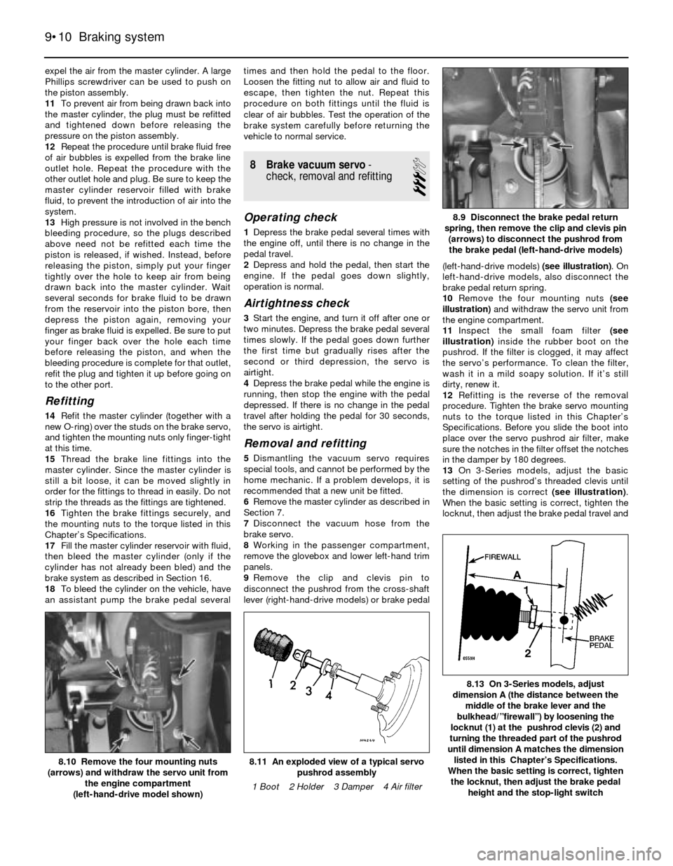
9Remove the clip and clevis pin to
disconnect the pushrod from the cross-shaft
lever (right-hand-drive models) or brake pedal(left-hand-drive models) (see illustration). On
left-hand-drive models, also disconnect the
brake pedal return spring.
10Remove the four mounting nuts (see
illustration)and withdraw the servo unit from
the engine compartment.
11Inspect the small foam filter (see
illustration)inside the rubber boot on the
pushrod. If the filter is clogged, it may affect
the servo’s performance. To clean the filter,
wash it in a mild soapy solution. If it’s still
dirty, renew it.
12Refitting is the reverse of the removal
procedure. Tighten the brake servo mounting
nuts to the torque listed in this Chapter’s
Specifications. Before you slide the boot into
place over the servo pushrod air filter, make
sure the notches in the filter offset the notches
in the damper by 180 degrees.
13On 3-Series models, adjust the basic
setting of the pushrod’s threaded clevis until
the dimension is correct (see illustration).
When the basic setting is correct, tighten the
locknut, then adjust the brake pedal travel and
9•10 Braking system
8.13 On 3-Series models, adjust
dimension A (the distance between the
middle of the brake lever and the
bulkhead/”firewall”) by loosening the
locknut (1) at the pushrod clevis (2) and
turning the threaded part of the pushrod
until dimension A matches the dimension
listed in this Chapter’s Specifications.
When the basic setting is correct, tighten
the locknut, then adjust the brake pedal
height and the stop-light switch
8.11 An exploded view of a typical servo
pushrod assembly
1 Boot 2 Holder 3 Damper 4 Air filter8.10 Remove the four mounting nuts
(arrows) and withdraw the servo unit from
the engine compartment
(left-hand-drive model shown)
8.9 Disconnect the brake pedal return
spring, then remove the clip and clevis pin
(arrows) to disconnect the pushrod from
the brake pedal (left-hand-drive models)
Page 139 of 228

the stop-light switch (see Section 13). Note:
On right-hand-drive models, the brake pedal
in on the right-hand side of the vehicle, and is
connected to the left-hand side by a cross-
shaft. The adjustment is carried out on the
pushrod at the left-hand side, but the
dimension is measured at the pedal on the
right-hand side.
14On 5-Series models, adjust the brake
pedal height and the stop-light switch (see
Section 13).
15Refit the master cylinder (see Section 7)
and attach the vacuum hose.
16Carefully test the operation of the brakes
before returning the vehicle to normal use
9 Hydraulic brake servo-
description, removal and
refitting
3
Warning: Brake fluid is
poisonous. It is also an effective
paint stripper. Refer to the
warning at the start of Section 16.
Description
1On 5-Series E28 (“old-shape”) models, a
hydraulic brake servo system is fitted. The
servo unit, located between the brake pedal
(left-hand-drive) or cross-shaft lever (right-
hand-drive) and the master cylinder, is
operated by hydraulic pressure generated by
the power steering pump. When the engine is
running, the power steering pump supplies
hydraulic pressure to a power flow regulator/
accumulator. The regulator/accumulator
stores and regulates the pressure to the
hydraulic brake servo. When you press the
brake pedal, the pressure in the servo helps
actuate the master cylinder, reducing pedal
effort.
2The hydraulic brake servo cannot be
overhauled; if it fails, a new one must be fitted.
Testing the system requires special tools, so
even fault diagnosis is beyond the scope of
the home mechanic. If the system fails, take it
to a dealer service department or other
qualified garage for repairs.
Removal and refitting
3With the engine off, discharge the hydraulic
accumulator by depressing the brake pedal
20 times or more.
4Remove the master cylinder (see Section 7).
5Clean the area around the return and
supply line fittings, then disconnect them.
Plug the lines, to prevent dirt from entering the
system, and to prevent further fluid loss.
Caution: Even a particle of dirt
can damage the servo, so be
extremely careful to prevent dirt
from entering the system while
the lines are disconnected.
6Working from inside the passenger
compartment, remove the lower left trim
panels above the brake pedal (left-hand-drive
models) or glovebox and trim (right-hand-drive models). On left-hand-drive models, also
disconnect the pedal return spring.
7Prise off the retaining clip, and disconnect
the pushrod from the brake pedal (see
illustration 8.9) or cross-shaft lever.
8Remove the four mounting nuts and
remove the brake servo (see illus-
tration 8.10).
9Refitting is the reverse of removal. Tighten
the hydraulic lines to the torque listed in this
Chapter’s Specifications. Note:Don’t try to
tighten these fittings without a torque wrench.
If they’re loose, they can leak, which can affect
system operation; if they’re tight, they can be
damaged, and they’ll also leak. You’ll need a
crowfoot-type split ring (“brake”) attachment
for your torque wrench to tighten the fittings
properly.
10When you’re done, bleed the brake
hydraulic system (Section 16) and adjust the
brake pedal travel and the stop-light switch
(see Section 13).
10 Handbrake cable(s)- renewal
2
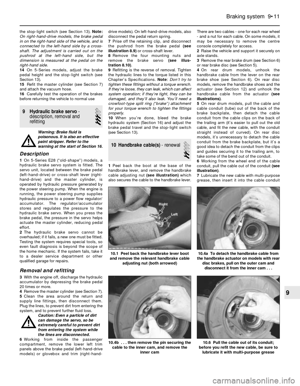
1Peel back the boot at the base of the
handbrake lever, and remove the handbrake
cable adjusting nut (see illustration)which
also secures the cable to the handbrake lever.There are two cables - one for each rear wheel
- and a nut for each cable. On some models, it
may be necessary to remove the centre
console completely for access.
2Raise the vehicle and support it securely on
axle stands.
3Remove the rear brake drum (see Section 6)
or rear brake disc (see Section 5).
4On rear drum models, unhook the
handbrake cable from the lever on the rear
brake shoe (see Section 6). On rear disc
models, remove the handbrake shoes and the
actuator (see Section 12) and unhook the
handbrake cable from the actuator (see
illustrations).
5On rear drum models, pull the cable and
cable conduit (tube) out of the back of the
brake backplate, then detach the cable
conduit from the cable clips on the back of
the trailing arm (it’s easier to pull out the old
cable, and fit the new cable, with the conduit
straight instead of curved). On rear disc
models, it’s unnecessary to detach the cable
conduit from the brake backplate, but it’s a
good idea to detach the conduit from the clips
and guides securing it to the trailing arm, to
take some of the bend out of the conduit.
6Working from the wheel end of the cable
conduit, pull the cable out of the conduit (see
illustration).
7Lubricate the new cable with multi-purpose
grease, then insert it into the cable conduit
Braking system 9•11
10.1 Peel back the handbrake lever boot
and remove the relevant handbrake cable
adjusting nut (both arrowed)
10.6 Pull the cable out of its conduit;
before you refit the new cable, be sure to
lubricate it with multi-purpose grease10.4b . . . then remove the pin securing the
cable to the inner cam, and remove the
inner cam
10.4a To detach the handbrake cable from
the handbrake actuator on models with rear
disc brakes, pull on the outer cam and
disconnect it from the inner cam . . .
9
Page 141 of 228

then back off the adjuster until the shoes
don’t drag (see Section 11). Refit the wheel
bolts, and tighten them to the torque given in
Chapter 1 Specifications.
13 Brake pedal- adjustment
1
Note:You should always adjust brake pedal
height after the master cylinder or brake servo
has been removed or renewed. You should
also adjust the stop-light switch (see Sec-
tion 14).
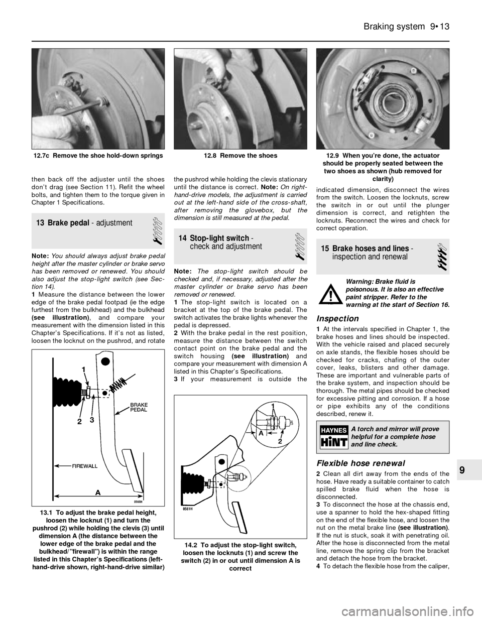
1Measure the distance between the lower
edge of the brake pedal footpad (ie the edge
furthest from the bulkhead) and the bulkhead
(see illustration), and compare your
measurement with the dimension listed in this
Chapter’s Specifications. If it’s not as listed,
loosen the locknut on the pushrod, and rotatethe pushrod while holding the clevis stationary
until the distance is correct. Note:On right-
hand-drive models, the adjustment is carried
out at the left-hand side of the cross-shaft,
after removing the glovebox, but the
dimension is still measured at the pedal.
14 Stop-light switch-
check and adjustment
1
Note:The stop-light switch should be
checked and, if necessary, adjusted after the
master cylinder or brake servo has been
removed or renewed.
1The stop-light switch is located on a
bracket at the top of the brake pedal. The
switch activates the brake lights whenever the
pedal is depressed.
2With the brake pedal in the rest position,
measure the distance between the switch
contact point on the brake pedal and the
switch housing (see illustration)and
compare your measurement with dimension A
listed in this Chapter’s Specifications.
3If your measurement is outside theindicated dimension, disconnect the wires
from the switch. Loosen the locknuts, screw
the switch in or out until the plunger
dimension is correct, and retighten the
locknuts. Reconnect the wires and check for
correct operation.
15 Brake hoses and lines-
inspection and renewal
4
Warning: Brake fluid is
poisonous. It is also an effective
paint stripper. Refer to the
warning at the start of Section 16.
Inspection
1At the intervals specified in Chapter 1, the
brake hoses and lines should be inspected.
With the vehicle raised and placed securely
on axle stands, the flexible hoses should be
checked for cracks, chafing of the outer
cover, leaks, blisters and other damage.
These are important and vulnerable parts of
the brake system, and inspection should be
thorough. The metal pipes should be checked
for excessive pitting and corrosion. If a hose
or pipe exhibits any of the conditions
described, renew it.
Flexible hose renewal
2Clean all dirt away from the ends of the
hose. Have ready a suitable container to catch
spilled brake fluid when the hose is
disconnected.
3To disconnect the hose at the chassis end,
use a spanner to hold the hex-shaped fitting
on the end of the flexible hose, and loosen the
nut on the metal brake line (see illustration).
If the nut is stuck, soak it with penetrating oil.
After the hose is disconnected from the metal
line, remove the spring clip from the bracket
and detach the hose from the bracket.
4To detach the flexible hose from the caliper,
Braking system 9•13
12.9 When you’re done, the actuator
should be properly seated between the
two shoes as shown (hub removed for
clarity)12.8 Remove the shoes12.7c Remove the shoe hold-down springs
14.2 To adjust the stop-light switch,
loosen the locknuts (1) and screw the
switch (2) in or out until dimension A is
correct
13.1 To adjust the brake pedal height,
loosen the locknut (1) and turn the
pushrod (2) while holding the clevis (3) until
dimension A (the distance between the
lower edge of the brake pedal and the
bulkhead/”firewall”) is within the range
listed in this Chapter’s Specifications (left-
hand-drive shown, right-hand-drive similar)
9
A torch and mirror will prove
helpful for a complete hose
and line check.
Page 220 of 228

REF•20Glossary of Technical Terms
A
ABS (Anti-lock brake system)A system,
usually electronically controlled, that senses
incipient wheel lockup during braking and
relieves hydraulic pressure at wheels that are
about to skid.
Air bag An inflatable bag hidden in the
steering wheel (driver’s side) or the dash or
glovebox (passenger side). In a head-on
collision, the bags inflate, preventing the
driver and front passenger from being thrown
forward into the steering wheel or windscreen.
Air cleanerA metal or plastic housing,
containing a filter element, which removes
dust and dirt from the air being drawn into the
engine.
Air filter elementThe actual filter in an air
cleaner system, usually manufactured from
pleated paper and requiring renewal at regular
intervals.
Allen keyA hexagonal wrench which fits into
a recessed hexagonal hole.
Alligator clipA long-nosed spring-loaded
metal clip with meshing teeth. Used to make
temporary electrical connections.
AlternatorA component in the electrical
system which converts mechanical energy
from a drivebelt into electrical energy to
charge the battery and to operate the starting
system, ignition system and electrical
accessories.
Ampere (amp)A unit of measurement for the
flow of electric current. One amp is the
amount of current produced by one volt
acting through a resistance of one ohm.
Anaerobic sealerA substance used to
prevent bolts and screws from loosening.
Anaerobic means that it does not require
oxygen for activation. The Loctite brand is
widely used.
AntifreezeA substance (usually ethylene
glycol) mixed with water, and added to a
vehicle’s cooling system, to prevent freezing
of the coolant in winter. Antifreeze also
contains chemicals to inhibit corrosion and
the formation of rust and other deposits thatwould tend to clog the radiator and coolant
passages and reduce cooling efficiency.
Anti-seize compoundA coating that
reduces the risk of seizing on fasteners that
are subjected to high temperatures, such as
exhaust manifold bolts and nuts.
AsbestosA natural fibrous mineral with great
heat resistance, commonly used in the
composition of brake friction materials.
Asbestos is a health hazard and the dust
created by brake systems should never be
inhaled or ingested.
AxleA shaft on which a wheel revolves, or
which revolves with a wheel. Also, a solid
beam that connects the two wheels at one
end of the vehicle. An axle which also
transmits power to the wheels is known as a
live axle.
AxleshaftA single rotating shaft, on either
side of the differential, which delivers power
from the final drive assembly to the drive
wheels. Also called a driveshaft or a halfshaft.
BBall bearingAn anti-friction bearing
consisting of a hardened inner and outer race
with hardened steel balls between two races.BearingThe curved surface on a shaft or in a
bore, or the part assembled into either, that
permits relative motion between them with
minimum wear and friction.
Big-end bearingThe bearing in the end of
the connecting rod that’s attached to the
crankshaft.
Bleed nippleA valve on a brake wheel
cylinder, caliper or other hydraulic component
that is opened to purge the hydraulic system
of air. Also called a bleed screw.
Brake bleedingProcedure for removing air
from lines of a hydraulic brake system.
Brake discThe component of a disc brake
that rotates with the wheels.
Brake drumThe component of a drum brake
that rotates with the wheels.
Brake liningsThe friction material which
contacts the brake disc or drum to retard the
vehicle’s speed. The linings are bonded or
riveted to the brake pads or shoes.
Brake padsThe replaceable friction pads
that pinch the brake disc when the brakes are
applied. Brake pads consist of a friction
material bonded or riveted to a rigid backing
plate.
Brake shoeThe crescent-shaped carrier to
which the brake linings are mounted and
which forces the lining against the rotating
drum during braking.
Braking systemsFor more information on
braking systems, consult the Haynes
Automotive Brake Manual.
Breaker barA long socket wrench handle
providing greater leverage.
BulkheadThe insulated partition between
the engine and the passenger compartment.
CCaliperThe non-rotating part of a disc-brake
assembly that straddles the disc and carries
the brake pads. The caliper also contains the
hydraulic components that cause the pads to
pinch the disc when the brakes are applied. A
caliper is also a measuring tool that can be set
to measure inside or outside dimensions of an
object.
Brake bleeding
Bearing
Axle assembly
Anti-seize compound
Alternator (exploded view)
Air filter