oxygen sensor BMW 3 SERIES 1987 E30 Workshop Manual
[x] Cancel search | Manufacturer: BMW, Model Year: 1987, Model line: 3 SERIES, Model: BMW 3 SERIES 1987 E30Pages: 228, PDF Size: 7.04 MB
Page 13 of 228

Tyre pressures (cold) - bars (psi)Front Rear
3-Series, E30
316 . . . . . . . . . . . . . . . . . . . . . . . . . . . . . . . . . . . . . . . . . . . . . . . . . . . 1.9 (28) 2.1 (30)
316i
Saloon . . . . . . . . . . . . . . . . . . . . . . . . . . . . . . . . . . . . . . . . . . . . . . . 2.0 (29) 2.1 (30)
Estate . . . . . . . . . . . . . . . . . . . . . . . . . . . . . . . . . . . . . . . . . . . . . . . 2.0 (29) 2.2 (32)
318i . . . . . . . . . . . . . . . . . . . . . . . . . . . . . . . . . . . . . . . . . . . . . . . . . . . 1.8 (26) 1.9 (28)
320i . . . . . . . . . . . . . . . . . . . . . . . . . . . . . . . . . . . . . . . . . . . . . . . . . . . 1.9 (28) 2.0 (29)
325i . . . . . . . . . . . . . . . . . . . . . . . . . . . . . . . . . . . . . . . . . . . . . . . . . . . 2.2 (32) 2.3 (33)
5-Series, E28 (“old-shape”)
518 and 518i . . . . . . . . . . . . . . . . . . . . . . . . . . . . . . . . . . . . . . . . . . . . 2.0 (29) 2.0 (29)
525i and 528i . . . . . . . . . . . . . . . . . . . . . . . . . . . . . . . . . . . . . . . . . . . 2.2 (32) 2.2 (32)
535i and M535i . . . . . . . . . . . . . . . . . . . . . . . . . . . . . . . . . . . . . . . . . . 2.3 (33) 2.5 (36)
5-Series, E34 (“new-shape”)
518i . . . . . . . . . . . . . . . . . . . . . . . . . . . . . . . . . . . . . . . . . . . . . . . . . . . 2.0 (29) 2.0 (29)
520i . . . . . . . . . . . . . . . . . . . . . . . . . . . . . . . . . . . . . . . . . . . . . . . . . . . 2.2 (32) 2.1 (30)
525i, 530i and 535i . . . . . . . . . . . . . . . . . . . . . . . . . . . . . . . . . . . . . . . 2.0 (29) 2.3 (33)
Torque wrench settingsNm
Automatic transmission sump bolts
Three-speed . . . . . . . . . . . . . . . . . . . . . . . . . . . . . . . . . . . . . . . . . . . . 8 to 9
Four-speed . . . . . . . . . . . . . . . . . . . . . . . . . . . . . . . . . . . . . . . . . . . . . 5 to 7
Spark plugs
M10 engines . . . . . . . . . . . . . . . . . . . . . . . . . . . . . . . . . . . . . . . . . . . . 20 to 30
Except M10 engines . . . . . . . . . . . . . . . . . . . . . . . . . . . . . . . . . . . . . . 30 to 33
Oxygen sensor . . . . . . . . . . . . . . . . . . . . . . . . . . . . . . . . . . . . . . . . . . . . 30 to 33
Wheel bolts . . . . . . . . . . . . . . . . . . . . . . . . . . . . . . . . . . . . . . . . . . . . . . . 100
Lubricants and fluids
Component or system Lubricant type/specification
Engine . . . . . . . . . . . . . . . . . . . . . . . . . . . . . . . . . . . . . . . . . . . . . . . . . . Multigrade engine oil, viscositySAE 10W/40 to 20W/50, to API SG
Cooling system . . . . . . . . . . . . . . . . . . . . . . . . . . . . . . . . . . . . . . . . . . . Ethylene glycol-based antifreeze with corrosion inhibitors
Manual transmission* . . . . . . . . . . . . . . . . . . . . . . . . . . . . . . . . . . . . . . Gear oil, viscosity SAE 80 to API-GL4, or single-grade mineral-based
engine oil, viscosity SAE 20, 30 or 40 to API-SG
Automatic transmission . . . . . . . . . . . . . . . . . . . . . . . . . . . . . . . . . . . . Dexron ll type ATF
Final drive . . . . . . . . . . . . . . . . . . . . . . . . . . . . . . . . . . . . . . . . . . . . . . . BMW-approved hypoid gear oil, viscosity SAE 90**
Brake and clutch hydraulic systems . . . . . . . . . . . . . . . . . . . . . . . . . . Hydraulic brake fluid to SAE J 1703 or DOT 4
Power steering . . . . . . . . . . . . . . . . . . . . . . . . . . . . . . . . . . . . . . . . . . . Dexron ll type ATF
* E34 520i & 525i with air conditioning, E34 530i & 535i - Dexron II type ATF)
** Only available in bulk; refer to your BMW dealer
Capacities*
1•3
1
Engine oil
M10 engines . . . . . . . . . . . . . . . . . . . . . . . . . . . . . . 4.0 litres
M20 engines . . . . . . . . . . . . . . . . . . . . . . . . . . . . . . 4.3 litres
M30 engines . . . . . . . . . . . . . . . . . . . . . . . . . . . . . . 5.8 litres
M40 engines . . . . . . . . . . . . . . . . . . . . . . . . . . . . . . 4.0 litres
Cooling system
M10 engines . . . . . . . . . . . . . . . . . . . . . . . . . . . . . . 7.0 litres
M20 engines . . . . . . . . . . . . . . . . . . . . . . . . . . . . . . 10.5 litres
M30 engines . . . . . . . . . . . . . . . . . . . . . . . . . . . . . . 12.0 litres
M40 engines . . . . . . . . . . . . . . . . . . . . . . . . . . . . . . 7.0 litres
Fuel tank
3-Series, E30
Saloon . . . . . . . . . . . . . . . . . . . . . . . . . . . . . . . . 55 litres (early),
64 litres (later)
Estate . . . . . . . . . . . . . . . . . . . . . . . . . . . . . . . . . 63 litres (early),
70 litres (later)
5-Series
E28 (“old-shape”) . . . . . . . . . . . . . . . . . . . . . . . . 70 litres
E34 (“new-shape”) . . . . . . . . . . . . . . . . . . . . . . . 81 litresManual transmission
ZF . . . . . . . . . . . . . . . . . . . . . . . . . . . . . . . . . . . . . . 1.2 litres
Getrag . . . . . . . . . . . . . . . . . . . . . . . . . . . . . . . . . . 1.0 to 1.5 litres
Automatic transmission (refill)
3-speed . . . . . . . . . . . . . . . . . . . . . . . . . . . . . . . . . 2.0 litres
4-speed . . . . . . . . . . . . . . . . . . . . . . . . . . . . . . . . . 3.0 litres
Final drive capacity (drain and refill)
3-Series, E30 . . . . . . . . . . . . . . . . . . . . . . . . . . . . . 0.9 litres
5-Series, E28 (“old-shape”) . . . . . . . . . . . . . . . . . . 0.9 litres
5-Series, E34 (“new-shape”) . . . . . . . . . . . . . . . . . 1.7 litres
*All capacities approximate
Servicing Specifications
Page 42 of 228
6 Exhaust manifold-
removal and refitting
1
Warning: Make sure the engine is
completely cool before beginning
work on the exhaust system.
Caution: If the radio in your
vehicle is equipped with an anti-
theft system, make sure you
have the correct activation code
before disconnecting the battery.
Note: If, after connecting the battery, the
wrong language appears on the instrument
panel display, refer to page 0-7 for the
language resetting procedure.
1Disconnect the battery negative cable.
2On models where the air cleaner is on the
exhaust manifold side of the engine, remove
the air cleaner housing assembly and/or
airflow sensor to provide sufficient working
area (see Chapter 4, if necessary).
3Unplug the HT leads and set the spark plug
lead harness aside (see Chapter 1).
4Clearly label, then disconnect or remove, all
wires, hoses, fittings, etc. that are in the way.
Be sure to disconnect the oxygen sensor,
where fitted.
5Raise the vehicle, and support it securely
on axle stands. Working from under the
vehicle, separate the exhaust downpipe from
the manifold. Use penetrating oil on the
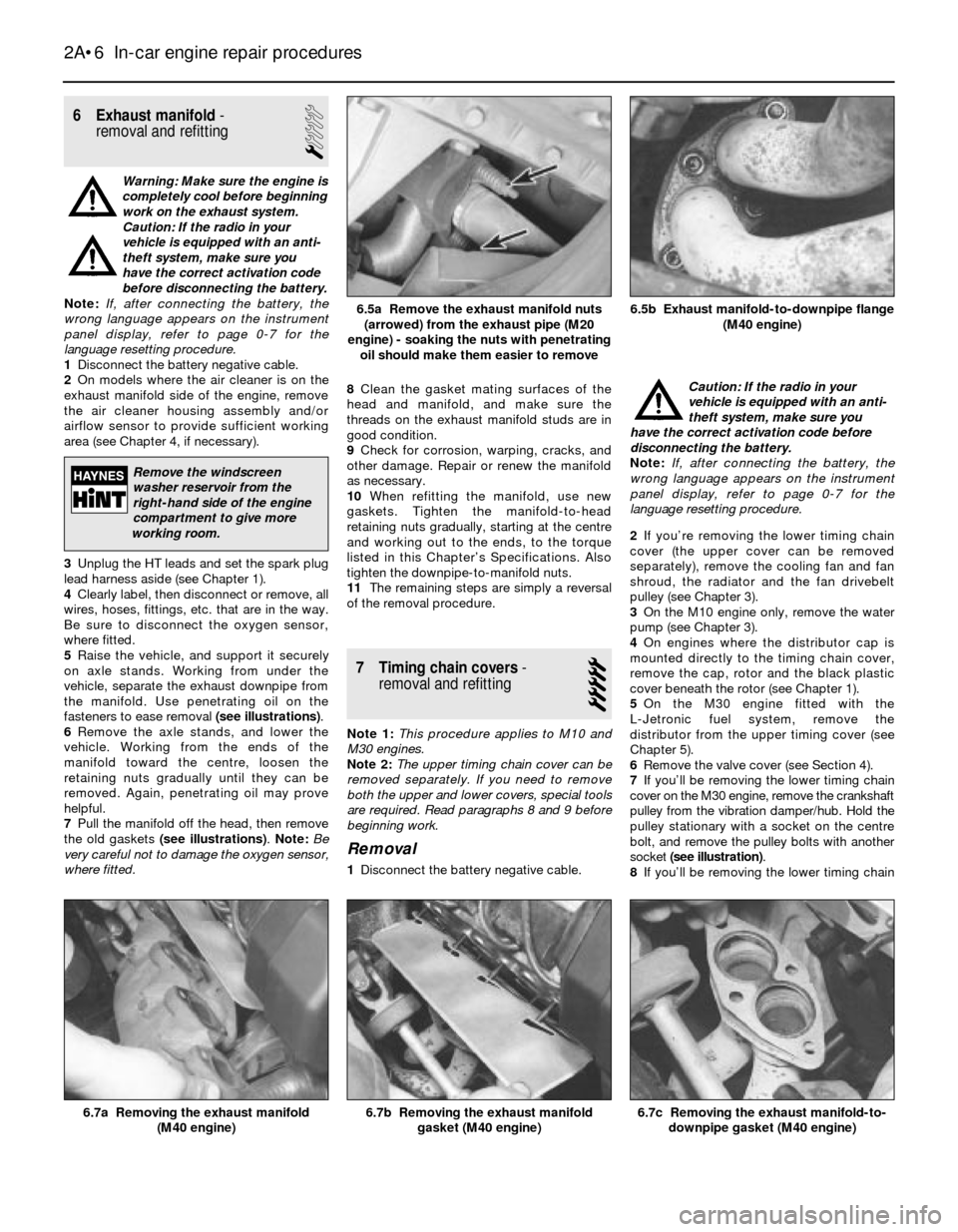
fasteners to ease removal (see illustrations).
6Remove the axle stands, and lower the
vehicle. Working from the ends of the
manifold toward the centre, loosen the
retaining nuts gradually until they can be
removed. Again, penetrating oil may prove
helpful.
7Pull the manifold off the head, then remove
the old gaskets (see illustrations). Note:Be
very careful not to damage the oxygen sensor,
where fitted.8Clean the gasket mating surfaces of the
head and manifold, and make sure the
threads on the exhaust manifold studs are in
good condition.
9Check for corrosion, warping, cracks, and
other damage. Repair or renew the manifold
as necessary.
10When refitting the manifold, use new
gaskets. Tighten the manifold-to-head
retaining nuts gradually, starting at the centre
and working out to the ends, to the torque
listed in this Chapter’s Specifications. Also
tighten the downpipe-to-manifold nuts.
11The remaining steps are simply a reversal
of the removal procedure.
7 Timing chain covers-
removal and refitting
5
Note 1:This procedure applies to M10 and
M30 engines.
Note 2:The upper timing chain cover can be
removed separately. If you need to remove
both the upper and lower covers, special tools
are required. Read paragraphs 8 and 9 before
beginning work.
Removal
1Disconnect the battery negative cable.Caution: If the radio in your
vehicle is equipped with an anti-
theft system, make sure you
have the correct activation code before
disconnecting the battery.
Note: If, after connecting the battery, the
wrong language appears on the instrument
panel display, refer to page 0-7 for the
language resetting procedure.
2If you’re removing the lower timing chain
cover (the upper cover can be removed
separately), remove the cooling fan and fan
shroud, the radiator and the fan drivebelt
pulley (see Chapter 3).
3On the M10 engine only, remove the water
pump (see Chapter 3).
4On engines where the distributor cap is
mounted directly to the timing chain cover,
remove the cap, rotor and the black plastic
cover beneath the rotor (see Chapter 1).
5On the M30 engine fitted with the
L-Jetronic fuel system, remove the
distributor from the upper timing cover (see
Chapter 5).
6Remove the valve cover (see Section 4).
7If you’ll be removing the lower timing chain
cover on the M30 engine, remove the crankshaft
pulley from the vibration damper/hub. Hold the
pulley stationary with a socket on the centre
bolt, and remove the pulley bolts with another
socket (see illustration).
8If you’ll be removing the lower timing chain
2A•6 In-car engine repair procedures
6.7c Removing the exhaust manifold-to-
downpipe gasket (M40 engine)6.7b Removing the exhaust manifold
gasket (M40 engine)6.7a Removing the exhaust manifold
(M40 engine)
6.5b Exhaust manifold-to-downpipe flange
(M40 engine)6.5a Remove the exhaust manifold nuts
(arrowed) from the exhaust pipe (M20
engine) - soaking the nuts with penetrating
oil should make them easier to remove
Remove the windscreen
washer reservoir from the
right-hand side of the engine
compartment to give more
working room.
Page 91 of 228
information on removing and refitting the
intake manifold, refer to Chapter 2A.
The throttle valve inside the throttle body or
carburettor is actuated by the accelerator
cable. When you depress the accelerator
pedal, the throttle plate opens and airflow
through the intake system increases.
On fuel injection systems, a flap inside the
airflow meter opens wider as the airflow
increases. A throttle position switch attached
to the pivot shaft of the flap detects the angle
of the flap (how much it’s open) and converts
this to a voltage signal, which it sends to the
computer.
Fuel system
On carburettor models, the fuel pump
supplies fuel under pressure to the
carburettor. A needle valve in the float
chamber maintains the fuel at a constant
level. A fuel return system channels excess
fuel back to the fuel tank.
On fuel injection models, an electric fuel
pump supplies fuel under constant pressure
to the fuel rail, which distributes fuel to the
injectors. The electric fuel pump is located
inside the fuel tank on later models, or beside
the fuel tank on early models. Early models
also have a transfer pump located in the fuel
tank. The transfer pump acts as an aid to the
larger main pump for delivering the necessary
pressure. A fuel pressure regulator controls
the pressure in the fuel system. The fuel
system also has a fuel pulsation damper
located near the fuel filter. The damper
reduces the pressure pulsations caused by
fuel pump operation, and the opening and
closing of the injectors. The amount of fuel
injected into the intake ports is precisely
controlled by an Electronic Control Unit (ECU
or computer). Some later 5-Series models
have a fuel cooler in the return line.
Electronic control system (fuel
injection system)
Besides altering the injector opening
duration as described above, the electronic
control unit performs a number of other tasks
related to fuel and emissions control. It
accomplishes these tasks by using data
relayed to it by a wide array of information
sensors located throughout the enginecompartment, comparing this information to
its stored map, and altering engine operation
by controlling a number of different actuators.
Since special equipment is required, most
fault diagnosis and repair of the electronic
control system is beyond the scope of the
home mechanic. Additional information and
testing procedures for the emissions system
components (oxygen sensor, coolant
temperature sensor, EVAP system, etc.) is
contained in Chapter 6.
2 Fuel injection system-
depressurising
1
Warning: Fuel is extremely
flammable, so take extra
precautions when you work on
any part of the fuel system. Don’t
smoke or allow open flames or bare light
bulbs near the work area. Also, don’t work
in a garage where a natural gas-type
appliance with a pilot light is present.
1Remove the fuel pump fuse from the main
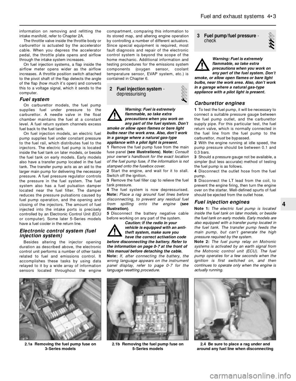
fuse panel (see illustrations). Note:Consult
your owner’s handbook for the exact location
of the fuel pump fuse, if the information is not
stamped onto the fusebox cover.
2Start the engine, and wait for it to stall.
Switch off the ignition.
3Remove the fuel filler cap to relieve the fuel
tank pressure.
4The fuel system is now depressurised.
Note:Place a rag around fuel lines before
disconnecting, to prevent any residual fuel
from spilling onto the engine(see
illustration).
5Disconnect the battery negative cable
before working on any part of the system.
Caution: If the radio in your
vehicle is equipped with an anti-
theft system, make sure you
have the correct activation code
before disconnecting the battery. Refer to
the information on page 0-7 at the front of
this manual before detaching the cable.
Note: If, after connecting the battery, the
wrong language appears on the instrument
panel display, refer to page 0-7 for the
language resetting procedure.
3 Fuel pump/fuel pressure-
check
3
Warning: Fuel is extremely
flammable, so take extra
precautions when you work on
any part of the fuel system. Don’t
smoke, or allow open flames or bare light
bulbs, near the work area. Also, don’t work
in a garage where a natural gas-type
appliance with a pilot light is present.
Carburettor engines
1To test the fuel pump, it will be necessary to
connect a suitable pressure gauge between
the fuel pump outlet, and the carburettor
supply pipe. For this particular test, the fuel
return valve, which is normally connected in
the fuel line from the fuel pump to the
carburettor, mustbe bypassed.
2With the engine running at idle speed, the
pump pressure should be between 0.1 and
0.3 bars.
3Should a pressure gauge not be available, a
simpler (but less accurate) method of testing
the fuel pump is as follows.
4Disconnect the outlet hose from the fuel
pump.
5Disconnect the LT lead from the coil, to
prevent the engine firing, then turn the engine
over on the starter. Well-defined spurts of fuel
should be ejected from the outlet hose.
Fuel injection engines
Note 1:The electric fuel pump is located
inside the fuel tank on later models, or beside
the fuel tank on early models. Early models are
also equipped with a transfer pump located in
the fuel tank. The transfer pump feeds the
main pump, but can’t generate the high
pressure required by the system.
Note 2:The fuel pump relay on Motronic
systems is activated by an earth signal from
the Motronic control unit (ECU). The fuel
pump operates for a few seconds when the
ignition is first switched on, and then
continues to operate only when the engine is
actually running.
Fuel and exhaust systems 4•3
2.4 Be sure to place a rag under and
around any fuel line when disconnecting2.1b Removing the fuel pump fuse on
5-Series models2.1a Removing the fuel pump fuse on
3-Series models
4
Page 102 of 228
Throttle positioner (2BE)
24Special tools are required to carry out a
comprehensive adjustment on the 2BE
carburettor. This work should therefore be left
to a BMW dealer.
13 Fuel injection -
general information
The fuel injection system is composed of
three basic sub-systems: fuel system, air
intake system and electronic control system.
Fuel system
An electric fuel pump, located inside the
fuel tank or beside the fuel tank, supplies fuel
under constant pressure to the fuel rail, which
distributes fuel evenly to all injectors. From
the fuel rail, fuel is injected into the intake
ports, just above the intake valves, by the fuel
injectors. The amount of fuel supplied by the
injectors is precisely controlled by an
Electronic Control Unit (ECU). An additional
injector, known as the cold start injector (L-
Jetronic and early Motronic systems only),
supplies extra fuel into the intake manifold for
starting. A pressure regulator controls system
pressure in relation to intake manifold
vacuum. A fuel filter between the fuel pump
and the fuel rail filters the fuel, to protect the
components of the system.
Air intake system
The air intake system consists of an air filter
housing, an airflow meter, a throttle body, the
intake manifold, and the associated ducting.
The airflow meter is an information-gathering
device for the ECU. These models are
equipped with the vane-type airflow meter. A
potentiometer measures intake airflow, and a
temperature sensor measures intake air
temperature. This information helps the ECU
determine the amount of fuel to be injected by
the injectors (injection duration). The throttle
plate inside the throttle body is controlled by
the driver. As the throttle plate opens, the
amount of air that can pass through the
system increases, so the potentiometer opens
further and the ECU signals the injectors to
increase the amount of fuel delivered to the
intake ports.
Electronic control system
The computer control system controls the
fuel system and other systems by means of
an Electronic Control Unit (ECU). The ECU
receives signals from a number of information
sensors which monitor such variables as
intake air volume, intake air temperature,
coolant temperature, engine rpm,
acceleration/deceleration, and exhaust
oxygen content. These signals help the ECU
determine the injection duration necessary for
the optimum air/fuel ratio. These sensors and
their corresponding ECU-controlled outputactuators are located throughout the engine
compartment. For further information
regarding the ECU and its relationship to the
engine electrical systems and ignition system,
refer to Chapters 5 and 6.
Either an L-Jetronic system or a Motronic
system is fitted. Later models have an
updated version of the original Motronic
system.
14 Fuel injection systems
L-Jetronic fuel injection system
The Bosch L-Jetronic fuel injection system
is used on most 3-Series models up to 1987,
and on most E28 (“old-shape”) 5-Series
models. It is an electronically-controlled fuel
injection system that utilises one solenoid-
operated fuel injector per cylinder. The system
is governed by an Electronic Control Unit
(ECU) which processes information sent by
various sensors, and in turn precisely
meters the fuel to the cylinders by
adjusting the amount of time that the injectors
are open.
An electric fuel pump delivers fuel under
high pressure to the injectors, through the fuel
feed line and an in-line filter. A pressure
regulator keeps fuel available at an optimum
pressure, allowing pressure to rise or fall
depending on engine speed and load. Any
excess fuel is returned to the fuel tank by a
separate line.
A sensor in the air intake duct constantly
measures the mass of the incoming air, and
the ECU adjusts the fuel mixture to provide an
optimum air/fuel ratio.
Other components incorporated in the
system are the throttle valve (which controls
airflow to the engine), the coolant temperature
sensor, the throttle position switch, idle
stabiliser valve (which bypasses air around
the throttle plate to control idle speed) and
associated relays and fuses.
Motronic fuel injection system
The Motronic system combines the fuel
control of the L-Jetronic fuel injection system
with the control of ignition timing, idle speed
and emissions into one control unit.
The fuel injection and idle speed control
functions are similar to those used on the L-
Jetronic system described above. For more
information on the Motronic system, see
Chapter 6.
An oxygen sensor is mounted in the
exhaust system on later models with a
catalytic converter. This sensor continually
reads the oxygen content of the exhaust gas.
The information is used by the ECU to adjust
the duration of injection, making it possible to
adjust the fuel mixture for optimum converter
efficiency and minimum emissions.
15 Fuel injection system-
check
2
Warning: Fuel is extremely
flammable, so take extra
precautions when you work on
any part of the fuel system. Don’t
smoke, or allow open flames or bare light
bulbs, near the work area. Don’t work in a
garage where a natural gas-type appliance
(such as a water heater or clothes dryer)
with a pilot light is present. If you spill any
fuel on your skin, rinse it off immediately
with soap and water. When you perform
any kind of work on the fuel system, wear
safety glasses, and have a fire
extinguisher on hand.
1Check the earth wire connections. Check
all wiring harness connectors that are related
to the system. Loose connectors and poor
earths can cause many problems that
resemble more serious malfunctions.
2Make sure the battery is fully charged, as
the control unit and sensors depend on an
accurate supply voltage in order to properly
meter the fuel.
3Check the air filter element - a dirty or
partially-blocked filter will severely impede
performance and economy (see Chapter 1).
4If a blown fuse is found, renew it and see if
it blows again. If it does, search for an earthed
wire in the harness related to the system.
5Check the air intake duct from the airflow
meter to the intake manifold for leaks. Intake
air leaks can cause a variety of problems. Also
check the condition of the vacuum hoses
connected to the intake manifold.
6Remove the air intake duct from the throttle
body, and check for dirt, carbon and other
residue build-up. If it’s dirty, clean it with
carburettor cleaner and a toothbrush.
7With the engine running, place a
screwdriver or a stethoscope against each
injector, one at a time, and listen for a clicking
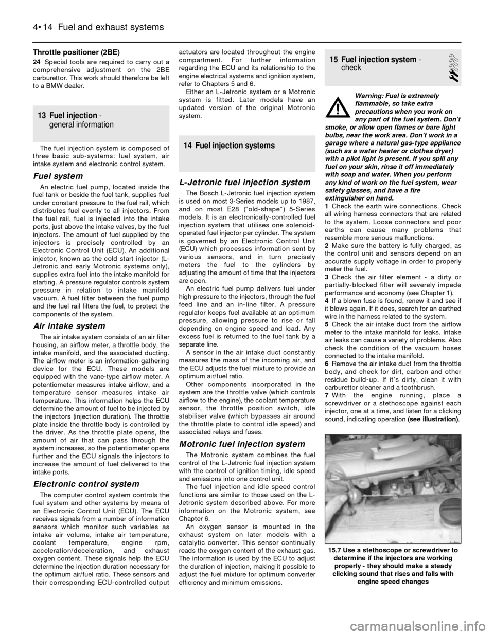
sound, indicating operation (see illustration).
4•14 Fuel and exhaust systems
15.7 Use a stethoscope or screwdriver to
determine if the injectors are working
properly - they should make a steady
clicking sound that rises and falls with
engine speed changes
Page 107 of 228
2L-Jetronic systems are equipped with a
separate idle speed control unit (computer)
located under the facia. The idle air stabiliser
valve has an adjusting screw. Early models
are equipped with plastic valves, but they still
can be adjusted by removing the hose and
inserting a very thin screwdriver inside.
3Early Motronic systems are also equipped
with a separate idle speed control unit
(computer) located under the facia. The idle
air stabiliser valve has an adjusting screw.
4On later Motronic systems, the idle air
stabiliser valve is ECU-controlled, and no
provision is made for adjustment.
Preliminary check
5Before performing any checks on the idle
air stabiliser valve, make sure these criteria
are met:
a) The engine must be at operating
temperature (60ºC)
b) Turn off all electrical accessories (air
conditioning, heater controls, headlights,
auxiliary cooling fan, etc)
c) The throttle position sensor must be
operating correctly (see Chapter 6)
d) There must not be any exhaust leaks
e) There must not be any vacuum leaks
f) Where fitted, the oxygen sensor must be
operating properly (see Chapter 6)
6Connect a tachometer in accordance with
the manufacturer’s instructions.
Caution: The ignition must be
switched off before making any
electrical connections.
7The idle air stabiliser valve operates
continuously when the ignition is on. Start the
engine and make sure the valve is vibrating
and humming slightly.
L-Jetronic system
Check
8With the engine running, disconnect the
electrical connector from the valve. The idle
speed should increase to about 2,000 rpm.
9If the idle speed does not increase, turn the
engine off. Using an ohmmeter, check the
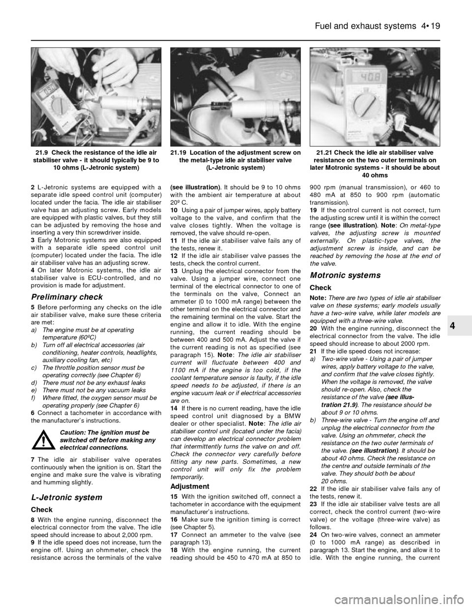
resistance across the terminals of the valve(see illustration). It should be 9 to 10 ohms
with the ambient air temperature at about
20º C.
10Using a pair of jumper wires, apply battery
voltage to the valve, and confirm that the
valve closes tightly. When the voltage is
removed, the valve should re-open.
11If the idle air stabiliser valve fails any of
the tests, renew it.
12If the idle air stabiliser valve passes the
tests, check the control current.
13Unplug the electrical connector from the
valve. Using a jumper wire, connect one
terminal of the electrical connector to one of
the terminals on the valve, Connect an
ammeter (0 to 1000 mA range) between the
other terminal on the electrical connector and
the remaining terminal on the valve. Start the
engine and allow it to idle. With the engine
running, the current reading should be
between 400 and 500 mA. Adjust the valve if
the current reading is not as specified (see
paragraph 15). Note: The idle air stabiliser
current will fluctuate between 400 and
1100 mA if the engine is too cold, if the
coolant temperature sensor is faulty, if the idle
speed needs to be adjusted, if there is an
engine vacuum leak or if electrical accessories
are on.
14If there is no current reading, have the idle
speed control unit diagnosed by a BMW
dealer or other specialist. Note: The idle air
stabiliser control unit (located under the facia)
can develop an electrical connector problem
that intermittently turns the valve on and off.
Check the connector very carefully before
fitting any new parts. Sometimes, a new
control unit will only fix the problem
temporarily.
Adjustment
15With the ignition switched off, connect a
tachometer in accordance with the equipment
manufacturer’s instructions.
16Make sure the ignition timing is correct
(see Chapter 5).
17Connect an ammeter to the valve (see
paragraph 13).
18With the engine running, the current
reading should be 450 to 470 mA at 850 to900 rpm (manual transmission), or 460 to
480 mA at 850 to 900 rpm (automatic
transmission).
19If the control current is not correct, turn
the adjusting screw until it is within the correct
range (see illustration). Note: On metal-type
valves, the adjusting screw is mounted
externally. On plastic-type valves, the
adjustment screw is inside, and can be
reached by removing the hose at the end of
the valve.
Motronic systems
Check
Note:There are two types of idle air stabiliser
valve on these systems; early models usually
have a two-wire valve, while later models are
equipped with a three-wire valve.
20With the engine running, disconnect the
electrical connector from the valve. The idle
speed should increase to about 2000 rpm.
21If the idle speed does not increase:
a) Two-wire valve - Using a pair of jumper
wires, apply battery voltage to the valve,
and confirm that the valve closes tightly.
When the voltage is removed, the valve
should re-open. Also, check the
resistance of the valve (see illus-
tration 21.9). The resistance should be
about 9 or 10 ohms.
b) Three-wire valve - Turn the engine off and
unplug the electrical connector from the
valve. Using an ohmmeter, check the
resistance on the two outer terminals of
the valve. (see illustration). It should be
about 40 ohms. Check the resistance on
the centre and outside terminals of the
valve. They should both be about
20 ohms.
22If the idle air stabiliser valve fails any of
the tests, renew it.
23If the idle air stabiliser valve tests are all
correct, check the control current (two-wire
valve) or the voltage (three-wire valve) as
follows.
24On two-wire valves, connect an ammeter
(0 to 1000 mA range) as described in
paragraph 13. Start the engine, and allow it to
idle. With the engine running, the current
Fuel and exhaust systems 4•19
21.21 Check the idle air stabiliser valve
resistance on the two outer terminals on
later Motronic systems - it should be about
40 ohms21.19 Location of the adjustment screw on
the metal-type idle air stabiliser valve
(L-Jetronic system)21.9 Check the resistance of the idle air
stabiliser valve - it should typically be 9 to
10 ohms (L-Jetronic system)
4
Page 110 of 228

Engine difficult to start, or fails to start (when cold)
Probable cause Corrective action
Cold start injector or thermotime switch
faulty (early Motronic system only) Test cold start injector and thermotime switch. Renew faulty components (see Section 19)
Fuel pump not running Check fuel pump fuse and fuel pump relay (see Sections 2 and 3)
Airflow meter flap (door) binding, or
stuck in open position Inspect the airflow meter for damage (see Section 16)
Fuel pressure incorrect Test system pressure (see Section 3)
Intake air leaks Inspect all vacuum lines, air ducts and oil filler and dipstick seals
Fuel injectors clogged or not operating Check fuel injectors (see Section 20) and wiring harness
Coolant temperature sensor faulty or Test coolant temperature sensor (see Chapter 6, Section 4)
wiring problem
TPS (throttle position sensor) incorrectly adjusted Check TPS adjustment (see Chapter 6, Section 4)
Dirt or other contaminants in fuel Check the fuel and drain the tank if necessary
Faulty ECU Have the ECU tested at a dealer service department or other specialist
Crankshaft position signal missing Faulty position sensor or flywheel, or reference pin missing (see Chapter 5)
Engine difficult to start, or fails to start (when warm)
Probable cause Corrective action
Cold start injector leaking or operating
continuously (early Motronic system only) Test cold start injector and thermotime switch (see Section 19)
Fuel pressure incorrect Test fuel pressure (see Section 3)
Insufficient residual fuel pressure Test fuel system hold pressure (see Section 3)
Fuel leak(s) Inspect fuel lines and fuel injectors for leaks. Correct leaks as necessary
Coolant temperature sensor faulty
or wiring problem Test coolant temperature sensor (see Chapter 6, Section 4)
Vapour lock (in warm weather) Check fuel pressure (see Section 3)
EVAP system faulty Check EVAP system (see Chapter 6, Section 6)
Faulty ECU Have the ECU tested at a dealer service department or other specialist
Idle speed control system faulty Test the idle air stabiliser valve (see Section 21)
Oxygen sensor faulty (where applicable) Check the oxygen sensor (see Chapter 6, Section 4)
Engine misses and hesitates under load
Probable cause Corrective action
Fuel injector clogged Test fuel injectors. Check for clogged injector lines. Renew faulty injectors (see Section 20)
Fuel pressure incorrect Test fuel system pressure (see Section 3). Test fuel pressure regulator (see Section 18)
Fuel leak(s) Inspect fuel lines and fuel injectors for leaks (see Chapter 4)
Engine maintenance Tune-up engine (see Chapter 1). Check the distributor cap, rotor, HT leads and spark
plugs, and renew any faulty components
Airflow meter flap (door) binding, or Inspect the airflow meter for damage (see Section 16)
stuck in open position
Intake air leaks Inspect all vacuum lines, air ducts, and oil filler and dipstick seals
Throttle position sensor (TPS) incorrectly adjusted Check TPS adjustment (see Chapter 6)
Engine idles too fast
Probable cause Corrective action
Accelerator pedal, cable or throttle valve binding Check for worn or broken components, kinked cable, or other damage. Renew faulty
components
Air leaking past throttle valve Inspect throttle valve, and adjust or renew as required
Engine has erratic idle speed
Probable cause Corrective action
Idle air stabiliser valve faulty Check the idle air stabiliser valve (see Section 21)
No power to the idle air stabiliser valve Check the idle air stabiliser relay and wiring circuit (see Chapter 12)
Idle speed control unit faulty Have the idle speed control unit checked by a dealer
Poor fuel economy
Probable cause Corrective action
Cold start injector leaking
(early Motronic system only) Test and, if necessary, renew cold start injector (see Section 19)
Oxygen sensor faulty (where applicable) Test the oxygen sensor (see Chapter 6, Section 4))
Sticking handbrake/binding brakes Check the handbrake/braking system (see Chapter 9)
Tyre pressures low Check tyre pressures (Chapter 1)
4•22 Fuel and exhaust systems
Page 124 of 228
4 Information sensors
2
Note:Refer to Chapters 4 and 5 for additional
information on the location and diagnosis of
the information sensors that are not covered in
this Section.
Coolant temperature sensor
General description
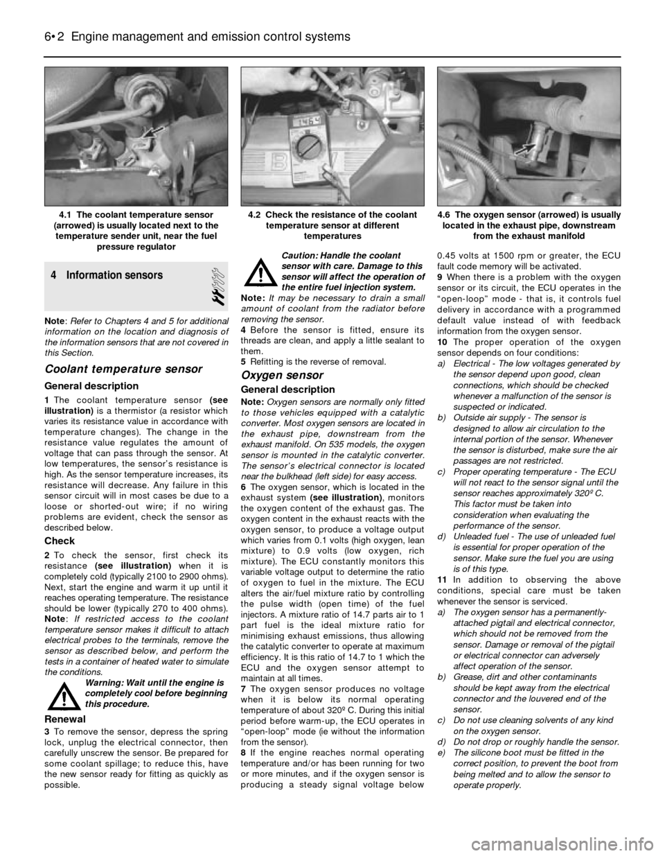
1The coolant temperature sensor (see
illustration)is a thermistor (a resistor which
varies its resistance value in accordance with
temperature changes). The change in the
resistance value regulates the amount of
voltage that can pass through the sensor. At
low temperatures, the sensor’s resistance is
high. As the sensor temperature increases, its
resistance will decrease. Any failure in this
sensor circuit will in most cases be due to a
loose or shorted-out wire; if no wiring
problems are evident, check the sensor as
described below.
Check
2To check the sensor, first check its
resistance (see illustration)when it is
completely cold (typically 2100 to 2900 ohms).
Next, start the engine and warm it up until it
reaches operating temperature. The resistance
should be lower (typically 270 to 400 ohms).
Note: If restricted access to the coolant
temperature sensor makes it difficult to attach
electrical probes to the terminals, remove the
sensor as described below, and perform the
tests in a container of heated water to simulate
the conditions.
Warning: Wait until the engine is
completely cool before beginning
this procedure.
Renewal
3To remove the sensor, depress the spring
lock, unplug the electrical connector, then
carefully unscrew the sensor. Be prepared for
some coolant spillage; to reduce this, have
the new sensor ready for fitting as quickly as
possible.Caution: Handle the coolant
sensor with care. Damage to this
sensor will affect the operation of
the entire fuel injection system.
Note: It may be necessary to drain a small
amount of coolant from the radiator before
removing the sensor.
4Before the sensor is fitted, ensure its
threads are clean, and apply a little sealant to
them.
5Refitting is the reverse of removal.
Oxygen sensor
General description
Note:Oxygen sensors are normally only fitted
to those vehicles equipped with a catalytic
converter. Most oxygen sensors are located in
the exhaust pipe, downstream from the
exhaust manifold. On 535 models, the oxygen
sensor is mounted in the catalytic converter.
The sensor’s electrical connector is located
near the bulkhead (left side) for easy access.
6The oxygen sensor, which is located in the
exhaust system (see illustration), monitors
the oxygen content of the exhaust gas. The
oxygen content in the exhaust reacts with the
oxygen sensor, to produce a voltage output
which varies from 0.1 volts (high oxygen, lean
mixture) to 0.9 volts (low oxygen, rich
mixture). The ECU constantly monitors this
variable voltage output to determine the ratio
of oxygen to fuel in the mixture. The ECU
alters the air/fuel mixture ratio by controlling
the pulse width (open time) of the fuel
injectors. A mixture ratio of 14.7 parts air to 1
part fuel is the ideal mixture ratio for
minimising exhaust emissions, thus allowing
the catalytic converter to operate at maximum
efficiency. It is this ratio of 14.7 to 1 which the
ECU and the oxygen sensor attempt to
maintain at all times.
7The oxygen sensor produces no voltage
when it is below its normal operating
temperature of about 320º C. During this initial
period before warm-up, the ECU operates in
“open-loop” mode (ie without the information
from the sensor).
8If the engine reaches normal operating
temperature and/or has been running for two
or more minutes, and if the oxygen sensor is
producing a steady signal voltage below 0.45 volts at 1500 rpm or greater, the ECU
fault code memory will be activated.
9When there is a problem with the oxygen
sensor or its circuit, the ECU operates in the
“open-loop” mode - that is, it controls fuel
delivery in accordance with a programmed
default value instead of with feedback
information from the oxygen sensor.
10The proper operation of the oxygen
sensor depends on four conditions:
a) Electrical - The low voltages generated by
the sensor depend upon good, clean
connections, which should be checked
whenever a malfunction of the sensor is
suspected or indicated.
b) Outside air supply - The sensor is
designed to allow air circulation to the
internal portion of the sensor. Whenever
the sensor is disturbed, make sure the air
passages are not restricted.
c) Proper operating temperature - The ECU
will not react to the sensor signal until the
sensor reaches approximately 320º C.
This factor must be taken into
consideration when evaluating the
performance of the sensor.
d) Unleaded fuel - The use of unleaded fuel
is essential for proper operation of the
sensor. Make sure the fuel you are using
is of this type.
11In addition to observing the above
conditions, special care must be taken
whenever the sensor is serviced.
a) The oxygen sensor has a permanently-
attached pigtail and electrical connector,
which should not be removed from the
sensor. Damage or removal of the pigtail
or electrical connector can adversely
affect operation of the sensor.
b) Grease, dirt and other contaminants
should be kept away from the electrical
connector and the louvered end of the
sensor.
c) Do not use cleaning solvents of any kind
on the oxygen sensor.
d) Do not drop or roughly handle the sensor.
e) The silicone boot must be fitted in the
correct position, to prevent the boot from
being melted and to allow the sensor to
operate properly.
6•2 Engine management and emission control systems
4.6 The oxygen sensor (arrowed) is usually
located in the exhaust pipe, downstream
from the exhaust manifold4.2 Check the resistance of the coolant
temperature sensor at different
temperatures4.1 The coolant temperature sensor
(arrowed) is usually located next to the
temperature sender unit, near the fuel
pressure regulator
Page 125 of 228
Check
12Warm up the engine, and let it run at idle.
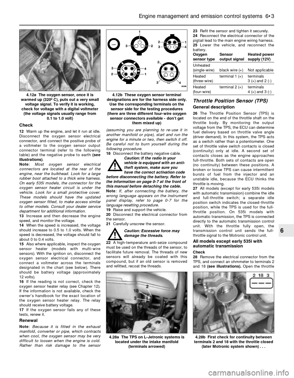
Disconnect the oxygen sensor electrical
connector, and connect the positive probe of
a voltmeter to the oxygen sensor output
connector terminal (refer to the following
table) and the negative probe to earth (see
illustrations).
Note:Most oxygen sensor electrical
connectors are located at the rear of the
engine, near the bulkhead. Look for a large
rubber boot attached to a thick wire harness.
On early 535i models, the connector for the
oxygen sensor heater circuit is under the
vehicle. Look for a small protective cover.
These models should have the updated
oxygen sensor fitted, to make access similar
to other models. Consult your dealer service
department for additional information.
13Increase and then decrease the engine
speed, and monitor the voltage.
14When the speed is increased, the voltage
should increase to 0.5 to 1.0 volts. When the
speed is decreased, the voltage should fall to
about 0 to 0.4 volts.
15Also where applicable, inspect the oxygen
sensor heater (models with multi-wire
sensors). With the ignition on, disconnect the
oxygen sensor electrical connector, and
connect a voltmeter across the terminals
designated in the chart (see below). There
should be battery voltage (approximately
12 volts).
16If the reading is not correct, check the
oxygen sensor heater relay (see Chapter 12).
If the information is not available, check the
owner’s handbook for the exact location of
the oxygen sensor heater relay. The relay
should receive battery voltage.
17If the oxygen sensor fails any of these
tests, renew it.
Renewal
Note: Because it is fitted in the exhaust
manifold, converter or pipe, which contracts
when cool, the oxygen sensor may be very
difficult to loosen when the engine is cold.
Rather than risk damage to the sensor(assuming you are planning to re-use it in
another manifold or pipe), start and run the
engine for a minute or two, then switch it off.
Be careful not to burn yourself during the
following procedure.
18Disconnect the battery negative cable.
Caution: If the radio in your
vehicle is equipped with an anti-
theft system, make sure you
have the correct activation code
before disconnecting the battery. Refer to
the information on page 0-7 at the front of
this manual before detaching the cable.
Note: If, after connecting the battery, the
wrong language appears on the instrument
panel display, refer to page 0-7 for the
language resetting procedure.
19Raise and support the vehicle.
20Disconnect the electrical connector from
the sensor.
21Carefully unscrew the sensor.
Caution: Excessive force may
damage the threads.
22A high-temperature anti-seize compound
must be used on the threads of the sensor, to
facilitate future removal. The threads of new
sensors will already be coated with this
compound, but if an old sensor is removed
and refitted, recoat the threads.23Refit the sensor and tighten it securely.
24Reconnect the electrical connector of the
pigtail lead to the main engine wiring harness.
25Lower the vehicle, and reconnect the
battery.
Oxygen Sensor Heated power
sensor type output signal supply (12V)
Unheated
(single-wire) black wire (+) Not applicable
Heated terminal 1 (+) terminals
(three-wire) 3 (+) and 2 (-)
Heated terminal 2 (+) terminals
(four-wire) 4 (+) and 3 (-)
Throttle Position Sensor (TPS)
General description
26The Throttle Position Sensor (TPS) is
located on the end of the throttle shaft on the
throttle body. By monitoring the output
voltage from the TPS, the ECU can determine
fuel delivery based on throttle valve angle
(driver demand). In this system, the TPS acts
as a switch rather than a potentiometer. One
set of throttle valve switch contacts is closed
(continuity) only at idle. A second set of
contacts closes as the engine approaches
full-throttle. Both sets of contacts are open
(no continuity) between these positions. A
broken or loose TPS can cause intermittent
bursts of fuel from the injector and an
unstable idle, because the ECU thinks the
throttle is moving.
27All models (except for early 535i models
with automatic transmission) combine the idle
and full-throttle switch; a separate idle
position switch indicates the closed-throttle
position, while the TPS is used for the full-
throttle position. On 535i models with
automatic transmission, the TPS is connected
directly to the automatic transmission control
unit. With the throttle fully open, the
transmission control unit sends the full-
throttle signal to the Motronic control unit.
All models except early 535i with
automatic transmission
Check
28Remove the electrical connector from the
TPS, and connect an ohmmeter to terminals 2
and 18 (see illustrations). Open the throttle
Engine management and emission control systems 6•3
4.12b These oxygen sensor terminal
designations are for the harness side only.
Use the corresponding terminals on the
sensor side for the testing procedures
(there are three different four-wire oxygen
sensor connectors available - don’t get
them mixed up)4.12a The oxygen sensor, once it is
warmed up (320º C), puts out a very small
voltage signal. To verify it is working,
check for voltage with a digital voltmeter
(the voltage signals usually range from
0.1 to 1.0 volt)
4.28b First check for continuity between
terminals 2 and 18 with the throttle closed
(later Motronic system shown) . . .4.28a The TPS on L-Jetronic systems is
located under the intake manifold
(terminals arrowed)
6
Page 223 of 228
REF•23
REF
Glossary of Technical Terms
JJump startStarting the engine of a vehicle
with a discharged or weak battery by
attaching jump leads from the weak battery to
a charged or helper battery.
LLoad Sensing Proportioning Valve (LSPV)A
brake hydraulic system control valve that
works like a proportioning valve, but also
takes into consideration the amount of weight
carried by the rear axle.
LocknutA nut used to lock an adjustment
nut, or other threaded component, in place.
For example, a locknut is employed to keep
the adjusting nut on the rocker arm in
position.
LockwasherA form of washer designed to
prevent an attaching nut from working loose.
MMacPherson strutA type of front
suspension system devised by Earle
MacPherson at Ford of England. In its original
form, a simple lateral link with the anti-roll bar
creates the lower control arm. A long strut - an
integral coil spring and shock absorber - is
mounted between the body and the steering
knuckle. Many modern so-called MacPherson
strut systems use a conventional lower A-arm
and don’t rely on the anti-roll bar for location.
MultimeterAn electrical test instrument with
the capability to measure voltage, current and
resistance.
NNOxOxides of Nitrogen. A common toxic
pollutant emitted by petrol and diesel engines
at higher temperatures.
OOhmThe unit of electrical resistance. One
volt applied to a resistance of one ohm will
produce a current of one amp.
OhmmeterAn instrument for measuring
electrical resistance.
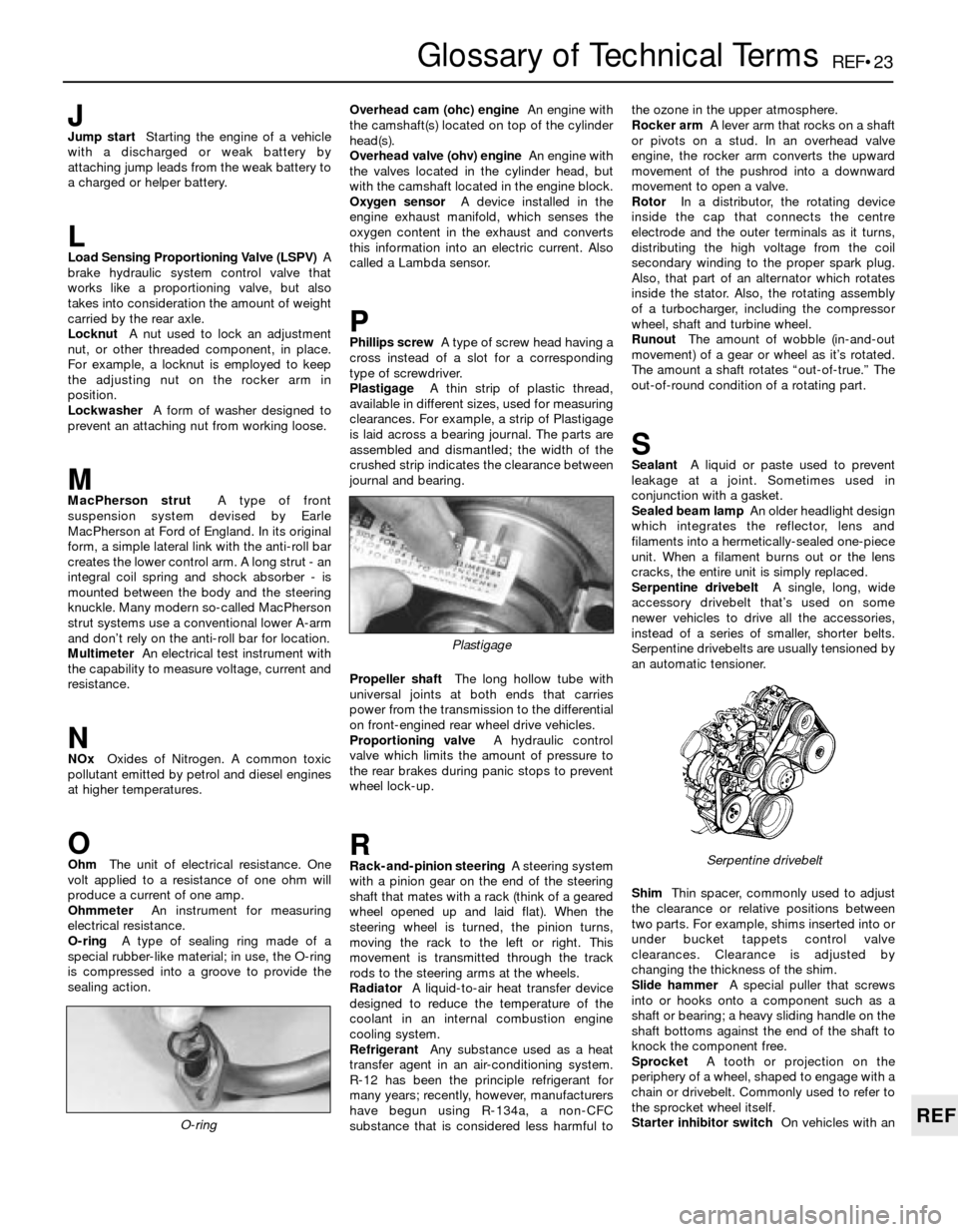
O-ringA type of sealing ring made of a
special rubber-like material; in use, the O-ring
is compressed into a groove to provide the
sealing action.Overhead cam (ohc) engineAn engine with
the camshaft(s) located on top of the cylinder
head(s).
Overhead valve (ohv) engineAn engine with
the valves located in the cylinder head, but
with the camshaft located in the engine block.
Oxygen sensorA device installed in the
engine exhaust manifold, which senses the
oxygen content in the exhaust and converts
this information into an electric current. Also
called a Lambda sensor.
PPhillips screwA type of screw head having a
cross instead of a slot for a corresponding
type of screwdriver.
PlastigageA thin strip of plastic thread,
available in different sizes, used for measuring
clearances. For example, a strip of Plastigage
is laid across a bearing journal. The parts are
assembled and dismantled; the width of the
crushed strip indicates the clearance between
journal and bearing.
Propeller shaftThe long hollow tube with
universal joints at both ends that carries
power from the transmission to the differential
on front-engined rear wheel drive vehicles.
Proportioning valveA hydraulic control
valve which limits the amount of pressure to
the rear brakes during panic stops to prevent
wheel lock-up.
RRack-and-pinion steeringA steering system
with a pinion gear on the end of the steering
shaft that mates with a rack (think of a geared
wheel opened up and laid flat). When the
steering wheel is turned, the pinion turns,
moving the rack to the left or right. This
movement is transmitted through the track
rods to the steering arms at the wheels.
RadiatorA liquid-to-air heat transfer device
designed to reduce the temperature of the
coolant in an internal combustion engine
cooling system.
RefrigerantAny substance used as a heat
transfer agent in an air-conditioning system.
R-12 has been the principle refrigerant for
many years; recently, however, manufacturers
have begun using R-134a, a non-CFC
substance that is considered less harmful tothe ozone in the upper atmosphere.
Rocker armA lever arm that rocks on a shaft
or pivots on a stud. In an overhead valve
engine, the rocker arm converts the upward
movement of the pushrod into a downward
movement to open a valve.
RotorIn a distributor, the rotating device
inside the cap that connects the centre
electrode and the outer terminals as it turns,
distributing the high voltage from the coil
secondary winding to the proper spark plug.
Also, that part of an alternator which rotates
inside the stator. Also, the rotating assembly
of a turbocharger, including the compressor
wheel, shaft and turbine wheel.
RunoutThe amount of wobble (in-and-out
movement) of a gear or wheel as it’s rotated.
The amount a shaft rotates “out-of-true.” The
out-of-round condition of a rotating part.
SSealantA liquid or paste used to prevent
leakage at a joint. Sometimes used in
conjunction with a gasket.
Sealed beam lampAn older headlight design
which integrates the reflector, lens and
filaments into a hermetically-sealed one-piece
unit. When a filament burns out or the lens
cracks, the entire unit is simply replaced.
Serpentine drivebeltA single, long, wide
accessory drivebelt that’s used on some
newer vehicles to drive all the accessories,
instead of a series of smaller, shorter belts.
Serpentine drivebelts are usually tensioned by
an automatic tensioner.
ShimThin spacer, commonly used to adjust
the clearance or relative positions between
two parts. For example, shims inserted into or
under bucket tappets control valve
clearances. Clearance is adjusted by
changing the thickness of the shim.
Slide hammerA special puller that screws
into or hooks onto a component such as a
shaft or bearing; a heavy sliding handle on the
shaft bottoms against the end of the shaft to
knock the component free.
SprocketA tooth or projection on the
periphery of a wheel, shaped to engage with a
chain or drivebelt. Commonly used to refer to
the sprocket wheel itself.
Starter inhibitor switchOn vehicles with an
O-ring
Serpentine drivebelt
Plastigage
Page 226 of 228

REF•26Index
E
Earth check - 12•2
Electric fan - 3•4
Electric shock - 0•5
Electric windows - 12•9
Electrical equipment - REF•2
Electrical system fault finding - 12•1
Electronic control system - 4•3, 4•14
Electronic control unit (ECU) - 6•1
Engine fault finding - REF•10
Engine tune-up - 1•7
Engine electrical systems- 5•1et seq
Engine electrical systems fault finding -
REF•11
Engine management and emission control
systems- 6•1et seq
Engine oil - 1•3, 1•7, 1•11
Environmental considerations - REF•8
Evaporative emissions control (EVAP)
system - 1•26, 6•5
Evaporator - 3•10
Exhaust emission checks - REF•4
Exhaust manifold - 2A•6
Exhaust system - 1•21, 4•20, REF•3
F
Fan - 3•4, 3•5
Fault finding- REF•9et seq
Fault finding - automatic transmission -
7B•2, REF•13
Fault finding - braking system - REF•14
Fault finding - clutch - REF•12
Fault finding - cooling system - REF•12
Fault finding - electrical system - 12•1,
REF•11
Fault finding - engine - REF•10
Fault finding - fuel system - 4•21, REF•12
Fault finding - manual transmission -
REF•13
Fault finding - suspension and steering -
REF•15
Filling - 11•3
Final drive - 8•2, 8•10, 8•11
Final drive oil - 1•3, 1•19, 1•26
Fire - 0•5
Flexible coupling - 8•7
Fluid level checks - 1•7
Fluid seals - 7B•5
Flywheel - 2A•18
Fuel and exhaust systems- 1•20, 4•1et
seq,REF•4
Fuel system fault finding - REF•12
Fuel filter - 1•25
Fuel hoses - 1•14
Fuel injection system - 4•3, 4•14
Fuel injection system - fault finding - 4•21
Fuel injectors - 4•18
Fuel level sender unit - 4•5, 4•6
Fuel lines and fittings - 4•7
Fuel pressure - 4•3
Fuel pressure regulator - 4•16
Fuel pump - 4•3, 4•4, 4•5
Fuel tank - 4•7, 4•8
Fume or gas intoxication - 0•5
Fuses - 12•2
G
Gaiters - 1•22, 8•9, 10•13
Gashes in bodywork - 11•2
Gaskets - REF•8
Gear lever - 7A•1
Gearbox - SeeManual transmission
Gearbox oil - 1•3, 1•19, 1•25
General engine overhaul procedures-
2B•1et seq
Glass - 11•4, 11•8
Glossary of technical terms - REF•20
Grille - 11•4
H
Handbrake - 1•23, 9•2, 9•12, REF•1
Handbrake fault - REF•14
Handles - 11•8
Hazard warning flasher - 12•2
HC emissions - REF•4
Headlights - 12•3, 12•5, 12•6
Heated rear window - 12•8
Heater - 3•2, 3•7, 3•8
Hinges - 11•4
HT leads - 1•18
Hubs - 10•8, 10•11, REF•3
Hydraulic servo - 9•11
Hydraulic tappets - 2B•11
Hydrofluoric acid - 0•5
I
Idle air stabiliser valve - 4•18
Idle speed adjustment - 1•15
Ignition coil - 5•5
Ignition control unit - 5•6, 5•7
Ignition sensors - 5•8
Ignition switch - 12•3
Ignition system - 5•3
Ignition timing - 5•4
Ignition timing sensors - 6•4
Impulse generator - 5•6, 5•7
In-car engine repair procedures- 2A•1et
seq
Indicators - 12•2, 12•3
Information sensors - 6•2
Injectors - 4•18
Input shaft - 7A•2
Instrument cluster - 12•4
Instrument panel language display - 0•7
Intake manifold - 2A•4
Intermediate shaft - 2A•12, 2B•14, 2B•19
Introduction to the BMW 3- and 5-Series -
0•4
J
Jacking - 0•8
Joint mating faces - REF•8
Jump starting - 0•9
K
Kickdown cable - 7B•3
L
L-Jetronic fuel injection system - 4•14,
4•19
Language display - 0•7
Latch - 11•8
Leaks - 0•10, 7B•3, REF•12, REF•13
Locknuts, locktabs and washers - REF•8
Locks - 11•4, 11•8
Lubricants - REF•18
M
Main bearings - 2B•17, 2B•19
Manifolds - 2A•4, 2A•6
Manual transmission- 7A•1et seq
Manual transmission fault finding - REF•13
Manual transmission oil - 1•3, 1•19, 1•25
Master cylinder - 8•3, 9•9
Mechanical fan - 3•4, 3•5
Mirrors - 11•8, REF•1
Misfire - REF•11
Mixture - REF•4
MOT test checks- REF•1 et seq
Motronic engine management system -
6•1
Motronic fuel injection system - 4•14, 4•19
Mountings - 2A•19, 7A•3
O
Oil - differential - 1•19, 1•26
Oil - engine - 1•3, 1•7, 1•11
Oil - final drive - 1•3
Oil - manual transmission - 1•3, 1•19, 1•25
Oil filter - 1•11, 1•12
Oil pump - 2A•16
Oil seals - 2A•12, 2A•13, 2A•19, 2B•20,
7A•2, 7B•5, 8•10, 8•12, REF•8
Open-circuit - 12•2
Output shaft - 7A•2, 7B•5
Overcooling - REF•12
Overheating - REF•12
Oxygen sensor - 6•2
P
Pads - 9•2, 9•3
Pedals - 8•3, 9•13
Pinion oil - 8•12
Pinking - REF•11
Piston rings - 2B•18
Pistons - 2B•12, 2B•16, 2B•21
Plastic components - 11•3
Poisonous or irritant substances - 0•5
Position sensors - 5•8
Positive crankcase ventilation (PCV)
system - 6•4
Power steering - 1•14, 10•15, 10•16
Power steering fluid - 1•12
Propeller shaft - 8•2, 8•6, 8•8
Pulse sensor - 5•8
Purge valve - 6•5