Compression check BMW 3 SERIES 1988 E30 User Guide
[x] Cancel search | Manufacturer: BMW, Model Year: 1988, Model line: 3 SERIES, Model: BMW 3 SERIES 1988 E30Pages: 228, PDF Size: 7.04 MB
Page 114 of 228

7 Ignition timing (TCI system)-
check and adjustment
4
Warning: Keep hands, equipment
and wires well clear of the
viscous cooling fan during
adjustment of the ignition timing.
Note:This Section describes the procedure
for checking and adjusting the ignition timing
on engines fitted with the TCI system. On
engines fitted with the Motronic engine
management system, the ignition timing is
controlled by the electronic control unit, and
no adjustment is possible. The timing can be
checked using the following procedure, but no
ignition timing values were available at the
time of writing. If the timing is thought to be
incorrect, refer to a BMW dealer.
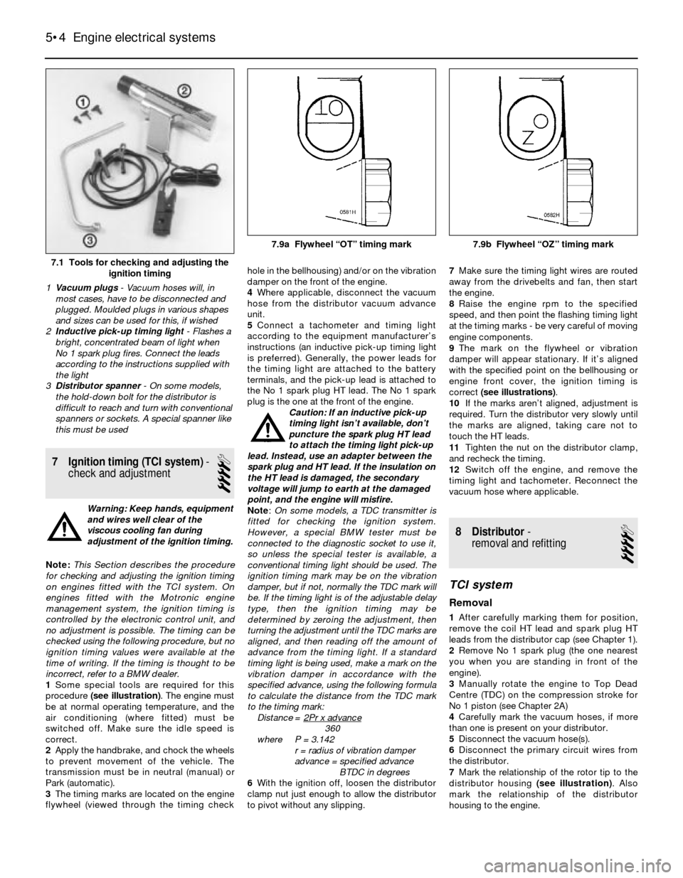
1Some special tools are required for this
procedure (see illustration). The engine must
be at normal operating temperature, and the
air conditioning (where fitted) must be
switched off. Make sure the idle speed is
correct.
2Apply the handbrake, and chock the wheels
to prevent movement of the vehicle. The
transmission must be in neutral (manual) or
Park (automatic).
3The timing marks are located on the engine
flywheel (viewed through the timing checkhole in the bellhousing) and/or on the vibration
damper on the front of the engine.
4Where applicable, disconnect the vacuum
hose from the distributor vacuum advance
unit.
5Connect a tachometer and timing light
according to the equipment manufacturer’s
instructions (an inductive pick-up timing light
is preferred). Generally, the power leads for
the timing light are attached to the battery
terminals, and the pick-up lead is attached to
the No 1 spark plug HT lead. The No 1 spark
plug is the one at the front of the engine.
Caution: If an inductive pick-up
timing light isn’t available, don’t
puncture the spark plug HT lead
to attach the timing light pick-up
lead. Instead, use an adapter between the
spark plug and HT lead. If the insulation on
the HT lead is damaged, the secondary
voltage will jump to earth at the damaged
point, and the engine will misfire.
Note:On some models, a TDC transmitter is
fitted for checking the ignition system.
However, a special BMW tester must be
connected to the diagnostic socket to use it,
so unless the special tester is available, a
conventional timing light should be used. The
ignition timing mark may be on the vibration
damper, but if not, normally the TDC mark will
be. If the timing light is of the adjustable delay
type, then the ignition timing may be
determined by zeroing the adjustment, then
turning the adjustment until the TDC marks are
aligned, and then reading off the amount of
advance from the timing light. If a standard
timing light is being used, make a mark on the
vibration damper in accordance with the
specified advance, using the following formula
to calculate the distance from the TDC mark
to the timing mark:
Distance = 2Pr x advance
360
where P = 3.142
r = radius of vibration damper
advance = specified advance
BTDC in degrees
6With the ignition off, loosen the distributor
clamp nut just enough to allow the distributor
to pivot without any slipping.7Make sure the timing light wires are routed
away from the drivebelts and fan, then start
the engine.
8Raise the engine rpm to the specified
speed, and then point the flashing timing light
at the timing marks - be very careful of moving
engine components.
9The mark on the flywheel or vibration
damper will appear stationary. If it’s aligned
with the specified point on the bellhousing or
engine front cover, the ignition timing is
correct (see illustrations).
10If the marks aren’t aligned, adjustment is
required. Turn the distributor very slowly until
the marks are aligned, taking care not to
touch the HT leads.
11Tighten the nut on the distributor clamp,
and recheck the timing.
12Switch off the engine, and remove the
timing light and tachometer. Reconnect the
vacuum hose where applicable.
8 Distributor-
removal and refitting
4
TCI system
Removal
1After carefully marking them for position,
remove the coil HT lead and spark plug HT
leads from the distributor cap (see Chapter 1).
2Remove No 1 spark plug (the one nearest
you when you are standing in front of the
engine).
3Manually rotate the engine to Top Dead
Centre (TDC) on the compression stroke for
No 1 piston (see Chapter 2A)
4Carefully mark the vacuum hoses, if more
than one is present on your distributor.
5Disconnect the vacuum hose(s).
6Disconnect the primary circuit wires from
the distributor.
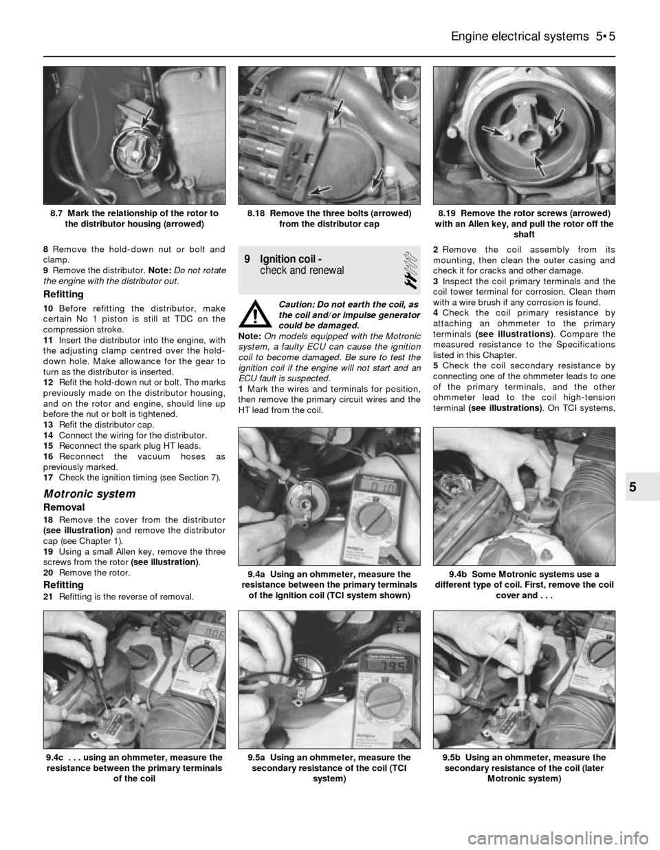
7Mark the relationship of the rotor tip to the
distributor housing (see illustration). Also
mark the relationship of the distributor
housing to the engine.
5•4 Engine electrical systems
7.1 Tools for checking and adjusting the
ignition timing
1Vacuum plugs- Vacuum hoses will, in
most cases, have to be disconnected and
plugged. Moulded plugs in various shapes
and sizes can be used for this, if wished
2Inductive pick-up timing light- Flashes a
bright, concentrated beam of light when
No 1 spark plug fires. Connect the leads
according to the instructions supplied with
the light
3Distributor spanner - On some models,
the hold-down bolt for the distributor is
difficult to reach and turn with conventional
spanners or sockets. A special spanner like
this must be used
7.9a Flywheel “OT” timing mark 7.9b Flywheel “OZ” timing mark
Page 115 of 228

8Remove the hold-down nut or bolt and
clamp.
9Remove the distributor. Note:Do not rotate
the engine with the distributor out.
Refitting
10Before refitting the distributor, make
certain No 1 piston is still at TDC on the
compression stroke.
11Insert the distributor into the engine, with
the adjusting clamp centred over the hold-
down hole. Make allowance for the gear to
turn as the distributor is inserted.
12Refit the hold-down nut or bolt. The marks
previously made on the distributor housing,
and on the rotor and engine, should line up
before the nut or bolt is tightened.
13Refit the distributor cap.
14Connect the wiring for the distributor.
15Reconnect the spark plug HT leads.
16Reconnect the vacuum hoses as
previously marked.
17Check the ignition timing (see Section 7).
Motronic system
Removal
18Remove the cover from the distributor
(see illustration)and remove the distributor
cap (see Chapter 1).
19Using a small Allen key, remove the three
screws from the rotor (see illustration).
20Remove the rotor.
Refitting
21Refitting is the reverse of removal.
9 Ignition coil -
check and renewal
2
Caution: Do not earth the coil, as
the coil and/or impulse generator
could be damaged.
Note:On models equipped with the Motronic
system, a faulty ECU can cause the ignition
coil to become damaged. Be sure to test the
ignition coil if the engine will not start and an
ECU fault is suspected.
1Mark the wires and terminals for position,
then remove the primary circuit wires and the
HT lead from the coil.2Remove the coil assembly from its
mounting, then clean the outer casing and
check it for cracks and other damage.
3Inspect the coil primary terminals and the
coil tower terminal for corrosion. Clean them
with a wire brush if any corrosion is found.
4Check the coil primary resistance by
attaching an ohmmeter to the primary
terminals (see illustrations). Compare the
measured resistance to the Specifications
listed in this Chapter.
5Check the coil secondary resistance by
connecting one of the ohmmeter leads to one
of the primary terminals, and the other
ohmmeter lead to the coil high-tension
terminal (see illustrations). On TCI systems,
Engine electrical systems 5•5
8.19 Remove the rotor screws (arrowed)
with an Allen key, and pull the rotor off the
shaft8.18 Remove the three bolts (arrowed)
from the distributor cap8.7 Mark the relationship of the rotor to
the distributor housing (arrowed)
9.5b Using an ohmmeter, measure the
secondary resistance of the coil (later
Motronic system)9.5a Using an ohmmeter, measure the
secondary resistance of the coil (TCI
system)
9.4b Some Motronic systems use a
different type of coil. First, remove the coil
cover and . . .9.4a Using an ohmmeter, measure the
resistance between the primary terminals
of the ignition coil (TCI system shown)
9.4c . . . using an ohmmeter, measure the
resistance between the primary terminals
of the coil
5
Page 225 of 228

REF•25
REF
Index
Note: References throughout this index relate to Chapter•page number
A
ABS - 9•2
Accelerator cable - 4•9
Acknowledgements - 0•4
Aerial - 12•4
Air bags - 0•5
Air cleaner - 4•8
Air conditioning system - 3•2, 3•7, 3•8,
3•9, 3•10
Air filter - 1•20
Air gap - 5•7
Air intake system - 4•2, 4•14
Airflow meter - 4•15, 6•4
Alternator - 5•10
Anti-lock Braking system (ABS) - 9•2
Anti-roll bar - 10•4, 10•9
Anti-theft audio system - 0•7
Antifreeze - 1•3, 1-8, 3•2
Asbestos - 0•5
ATF - 1•3, 1•13, 1•23
Automatic choke - 4•13
Automatic transmission- 7B•1et seq
Automatic transmission fault finding -
7B•4, REF•13
Automatic transmission fluid - 1•3, 1•13,
1•23
B
Backfire - REF•11
Balljoints - 10•7
Battery - 0•5, 1•16, 5•2
Battery fault - REF•11
Big-end bearings - 2B•17, 2B•21
Bleeding brakes - 9•14
Bleeding clutch - 8•4
Bleeding power steering - 10•16Block - 2B•14, 2B•15
Blower motor - 3•7
Body corrosion - REF•4
Body electrical systems- 12•1et seq
Bodywork and fittings- 11•1et seq
Bonnet - 11•4
Boot lid - 11•6
Boots - 8•9, 10•13
Brake fluid - 1•3, 1•9
Brake lines and hoses - 1•22, 9•13
Braking system- 1•22, 9•1et seq,REF•1,
REF•2, REF•3
Braking system fault finding - REF•14
Bulbs - 12•6
Bumpers - 11•6
Burning - 0•5
C
Cables - 4•9, 5•2, 7B•3, 9•12
Calipers - 9•4
Cam followers - 2B•11
Camshaft - 2A•12, 2B•11
Carburettor - 4•10, 4•11
Carpets - 11•2
Catalytic converter - 4•20, 6•6
Central locking - 12•8
Charging - 1•17, 5•9
Chemicals - REF•18
Choke - 4•13
Clutch and driveline- 8•1et seq
Clutch fault finding - REF•12
Clutch fluid - 1•3, 1•9
CO level adjustment - 1•15, REF•4
Coil - 5•5
Coil springs - 10•7, 10•9
Cold start injectors - 4•17, 4•18
Compression check - 2B•4Compressor - 3•8
Condenser - 3•9
Connecting rods -2B•12, 2B•16, 2B•21
Constant velocity (CV) joint - 8•2, 8•8, 8•9
Continuity check - 12•2
Control arm - 10•4, 10•5
Conversion factors - REF•17
Coolant - 1•3, 1•8
Coolant pump - 3•5
Coolant temperature sender unit - 3•6
Coolant temperature sensor - 6•2
Cooling fan - 3•4
Cooling, heating and air conditioning
systems- 1•21, 1•24, 3•1et seq
Cooling system fault finding - REF•12
Crankshaft - 2A•12, 2A•13, 2A•19, 2B•13,
2B•17, 2B•19, 2B•20
Cruise control - 12•3, 12•8
Crushing - 0•5
Cushion - 11•9
CV joints - 8•2, 8•8, 8•9
Cylinder head - 2A•13, 2B•7, 2B•10, 2B•12
Cylinder honing - 2B•15
D
Dents in bodywork - 11•2
Differential (final drive) - 8•2, 8•10, 8•11
Differential oil -1•3, 1•19, 1•26
Direction indicators - 12•2, 12•3
Discs - 1•22, 9•5
Distributor - 1•18, 5•4
Door - 11•6, 11•8, REF•2
Drivebelts - 1•14
Driveplate - 2A•18
Driveshafts - 1•22, 8•2, 8•9
Drums - 1•23