Fuel lines BMW 3 SERIES 1988 E30 User Guide
[x] Cancel search | Manufacturer: BMW, Model Year: 1988, Model line: 3 SERIES, Model: BMW 3 SERIES 1988 E30Pages: 228, PDF Size: 7.04 MB
Page 94 of 228
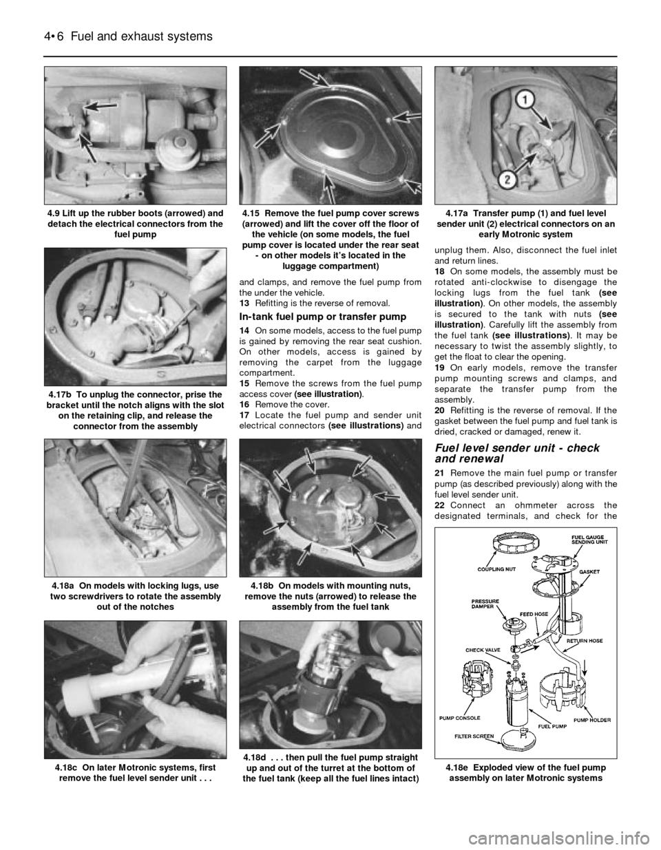
and clamps, and remove the fuel pump from
the under the vehicle.
13Refitting is the reverse of removal.
In-tank fuel pump or transfer pump
14On some models, access to the fuel pump
is gained by removing the rear seat cushion.
On other models, access is gained by
removing the carpet from the luggage
compartment.
15Remove the screws from the fuel pump
access cover (see illustration).
16Remove the cover.
17Locate the fuel pump and sender unit
electrical connectors (see illustrations)andunplug them. Also, disconnect the fuel inlet
and return lines.
18On some models, the assembly must be
rotated anti-clockwise to disengage the
locking lugs from the fuel tank (see
illustration). On other models, the assembly
is secured to the tank with nuts (see
illustration). Carefully lift the assembly from
the fuel tank (see illustrations). It may be
necessary to twist the assembly slightly, to
get the float to clear the opening.
19On early models, remove the transfer
pump mounting screws and clamps, and
separate the transfer pump from the
assembly.
20Refitting is the reverse of removal. If the
gasket between the fuel pump and fuel tank is
dried, cracked or damaged, renew it.
Fuel level sender unit - check
and renewal
21Remove the main fuel pump or transfer
pump (as described previously) along with the
fuel level sender unit.
22Connect an ohmmeter across the
designated terminals, and check for the
4•6 Fuel and exhaust systems
4.18e Exploded view of the fuel pump
assembly on later Motronic systems4.18d . . . then pull the fuel pump straight
up and out of the turret at the bottom of
the fuel tank (keep all the fuel lines intact)4.18c On later Motronic systems, first
remove the fuel level sender unit . . .
4.18b On models with mounting nuts,
remove the nuts (arrowed) to release the
assembly from the fuel tank4.18a On models with locking lugs, use
two screwdrivers to rotate the assembly
out of the notches
4.17b To unplug the connector, prise the
bracket until the notch aligns with the slot
on the retaining clip, and release the
connector from the assembly
4.17a Transfer pump (1) and fuel level
sender unit (2) electrical connectors on an
early Motronic system4.15 Remove the fuel pump cover screws
(arrowed) and lift the cover off the floor of
the vehicle (on some models, the fuel
pump cover is located under the rear seat
- on other models it’s located in the
luggage compartment)4.9 Lift up the rubber boots (arrowed) and
detach the electrical connectors from the
fuel pump
Page 95 of 228
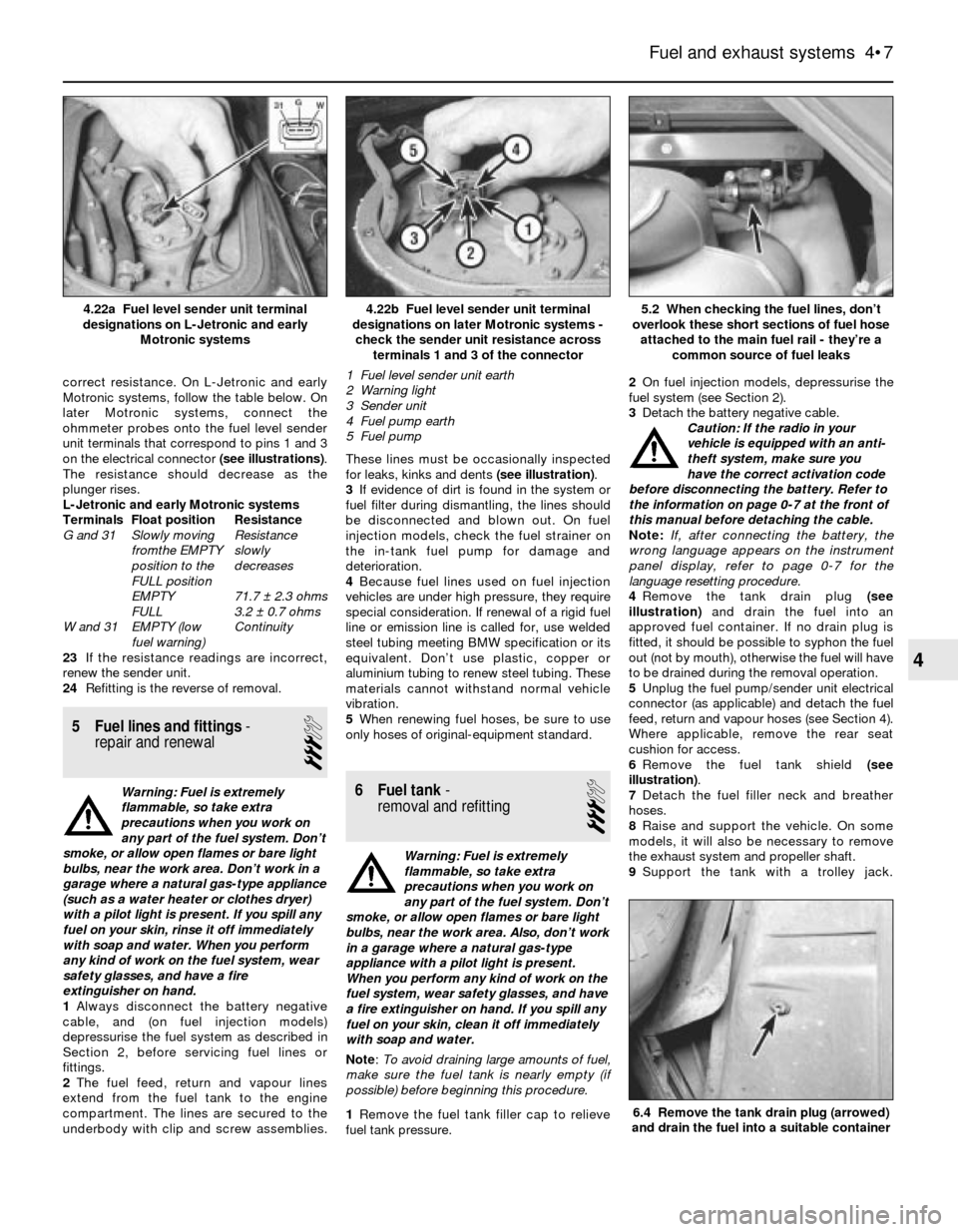
correct resistance. On L-Jetronic and early
Motronic systems, follow the table below. On
later Motronic systems, connect the
ohmmeter probes onto the fuel level sender
unit terminals that correspond to pins 1 and 3
on the electrical connector (see illustrations).
The resistance should decrease as the
plunger rises.
L-Jetronic and early Motronic systems
Terminals Float position Resistance
G and 31 Slowly moving Resistance
fromthe EMPTY slowly
position to the decreases
FULL position
EMPTY 71.7 ± 2.3 ohms
FULL 3.2 ± 0.7 ohms
W and 31 EMPTY (low Continuity
fuel warning)
23If the resistance readings are incorrect,
renew the sender unit.
24Refitting is the reverse of removal.
5 Fuel lines and fittings-
repair and renewal
3
Warning: Fuel is extremely
flammable, so take extra
precautions when you work on
any part of the fuel system. Don’t
smoke, or allow open flames or bare light
bulbs, near the work area. Don’t work in a
garage where a natural gas-type appliance
(such as a water heater or clothes dryer)
with a pilot light is present. If you spill any
fuel on your skin, rinse it off immediately
with soap and water. When you perform
any kind of work on the fuel system, wear
safety glasses, and have a fire
extinguisher on hand.
1Always disconnect the battery negative
cable, and (on fuel injection models)
depressurise the fuel system as described in
Section 2, before servicing fuel lines or
fittings.
2The fuel feed, return and vapour lines
extend from the fuel tank to the engine
compartment. The lines are secured to the
underbody with clip and screw assemblies.These lines must be occasionally inspected
for leaks, kinks and dents (see illustration).
3If evidence of dirt is found in the system or
fuel filter during dismantling, the lines should
be disconnected and blown out. On fuel
injection models, check the fuel strainer on
the in-tank fuel pump for damage and
deterioration.
4Because fuel lines used on fuel injection
vehicles are under high pressure, they require
special consideration. If renewal of a rigid fuel
line or emission line is called for, use welded
steel tubing meeting BMW specification or its
equivalent. Don’t use plastic, copper or
aluminium tubing to renew steel tubing. These
materials cannot withstand normal vehicle
vibration.
5When renewing fuel hoses, be sure to use
only hoses of original-equipment standard.6 Fuel tank-
removal and refitting
3
Warning: Fuel is extremely
flammable, so take extra
precautions when you work on
any part of the fuel system. Don’t
smoke, or allow open flames or bare light
bulbs, near the work area. Also, don’t work
in a garage where a natural gas-type
appliance with a pilot light is present.
When you perform any kind of work on the
fuel system, wear safety glasses, and have
a fire extinguisher on hand. If you spill any
fuel on your skin, clean it off immediately
with soap and water.
Note: To avoid draining large amounts of fuel,
make sure the fuel tank is nearly empty (if
possible) before beginning this procedure.
1Remove the fuel tank filler cap to relieve
fuel tank pressure.2On fuel injection models, depressurise the
fuel system (see Section 2).
3Detach the battery negative cable.
Caution: If the radio in your
vehicle is equipped with an anti-
theft system, make sure you
have the correct activation code
before disconnecting the battery. Refer to
the information on page 0-7 at the front of
this manual before detaching the cable.
Note: If, after connecting the battery, the
wrong language appears on the instrument
panel display, refer to page 0-7 for the
language resetting procedure.
4Remove the tank drain plug (see
illustration)and drain the fuel into an
approved fuel container. If no drain plug is
fitted, it should be possible to syphon the fuel
out (not by mouth), otherwise the fuel will have
to be drained during the removal operation.
5Unplug the fuel pump/sender unit electrical
connector (as applicable) and detach the fuel
feed, return and vapour hoses (see Section 4).
Where applicable, remove the rear seat
cushion for access.
6Remove the fuel tank shield (see
illustration).
7Detach the fuel filler neck and breather
hoses.
8Raise and support the vehicle. On some
models, it will also be necessary to remove
the exhaust system and propeller shaft.
9Support the tank with a trolley jack.
Fuel and exhaust systems 4•7
4.22b Fuel level sender unit terminal
designations on later Motronic systems -
check the sender unit resistance across
terminals 1 and 3 of the connector
1 Fuel level sender unit earth
2 Warning light
3 Sender unit
4 Fuel pump earth
5 Fuel pump4.22a Fuel level sender unit terminal
designations on L-Jetronic and early
Motronic systems
6.4 Remove the tank drain plug (arrowed)
and drain the fuel into a suitable container
5.2 When checking the fuel lines, don’t
overlook these short sections of fuel hose
attached to the main fuel rail - they’re a
common source of fuel leaks
4
Page 108 of 228
reading should be between 400 and 500 mA.
Adjust the valve if the current reading is not as
specified. Note: The idle air stabiliser current
will fluctuate between 400 and 1100 mA if the
engine is too cold, if the coolant temperature
sensor is faulty, if there is an engine vacuum
leak, or if electrical accessories are on.
25If there is no current reading, have the idle
speed control unit (under the facia) checked
by a BMW dealer or other specialist.
26On three-wire valves, check for voltage at
the electrical connector. With the ignition on,
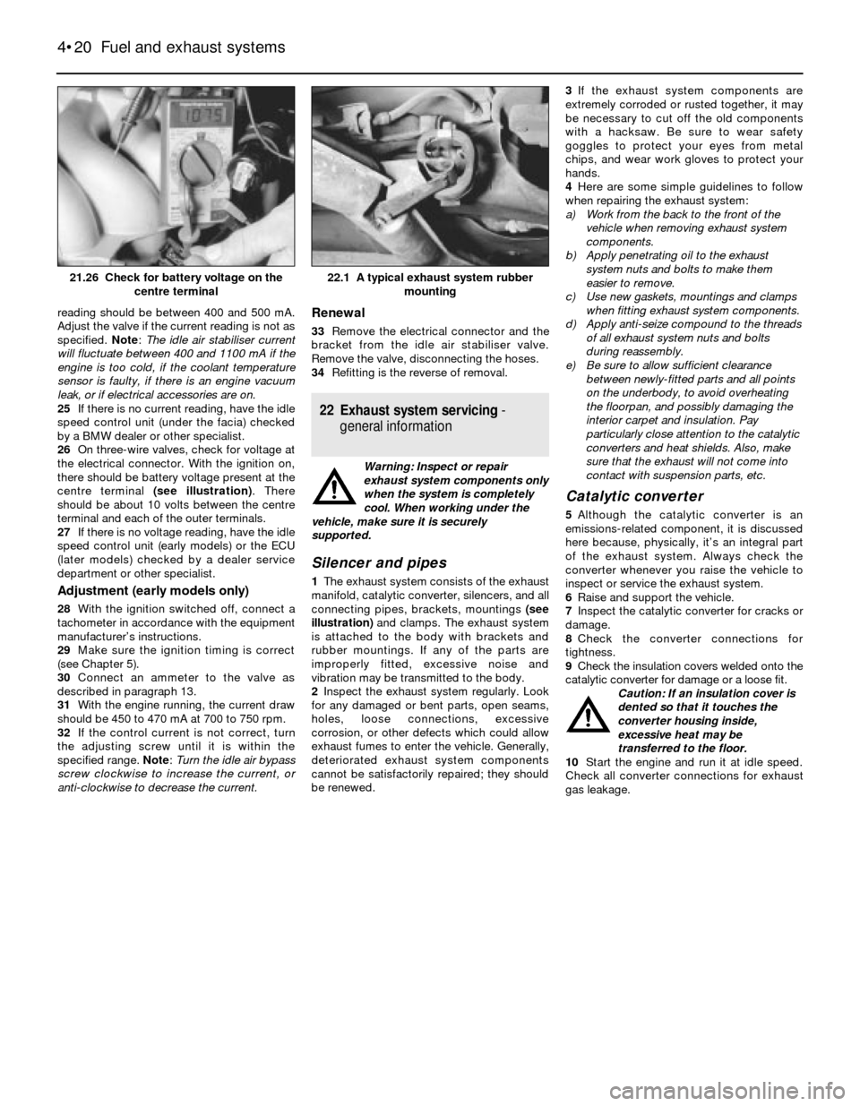
there should be battery voltage present at the
centre terminal (see illustration). There
should be about 10 volts between the centre
terminal and each of the outer terminals.
27If there is no voltage reading, have the idle
speed control unit (early models) or the ECU
(later models) checked by a dealer service
department or other specialist.
Adjustment (early models only)
28With the ignition switched off, connect a
tachometer in accordance with the equipment
manufacturer’s instructions.
29Make sure the ignition timing is correct
(see Chapter 5).
30Connect an ammeter to the valve as
described in paragraph 13.
31With the engine running, the current draw
should be 450 to 470 mA at 700 to 750 rpm.
32If the control current is not correct, turn
the adjusting screw until it is within the
specified range. Note: Turn the idle air bypass
screw clockwise to increase the current, or
anti-clockwise to decrease the current.
Renewal
33Remove the electrical connector and the
bracket from the idle air stabiliser valve.
Remove the valve, disconnecting the hoses.
34Refitting is the reverse of removal.
22 Exhaust system servicing-
general information
Warning: Inspect or repair
exhaust system components only
when the system is completely
cool. When working under the
vehicle, make sure it is securely
supported.
Silencer and pipes
1The exhaust system consists of the exhaust
manifold, catalytic converter, silencers, and all
connecting pipes, brackets, mountings (see
illustration)and clamps. The exhaust system
is attached to the body with brackets and
rubber mountings. If any of the parts are
improperly fitted, excessive noise and
vibration may be transmitted to the body.
2Inspect the exhaust system regularly. Look
for any damaged or bent parts, open seams,
holes, loose connections, excessive
corrosion, or other defects which could allow
exhaust fumes to enter the vehicle. Generally,
deteriorated exhaust system components
cannot be satisfactorily repaired; they should
be renewed.3If the exhaust system components are
extremely corroded or rusted together, it may
be necessary to cut off the old components
with a hacksaw. Be sure to wear safety
goggles to protect your eyes from metal
chips, and wear work gloves to protect your
hands.
4Here are some simple guidelines to follow
when repairing the exhaust system:
a) Work from the back to the front of the
vehicle when removing exhaust system
components.
b) Apply penetrating oil to the exhaust
system nuts and bolts to make them
easier to remove.
c) Use new gaskets, mountings and clamps
when fitting exhaust system components.
d) Apply anti-seize compound to the threads
of all exhaust system nuts and bolts
during reassembly.
e) Be sure to allow sufficient clearance
between newly-fitted parts and all points
on the underbody, to avoid overheating
the floorpan, and possibly damaging the
interior carpet and insulation. Pay
particularly close attention to the catalytic
converters and heat shields. Also, make
sure that the exhaust will not come into
contact with suspension parts, etc.
Catalytic converter
5Although the catalytic converter is an
emissions-related component, it is discussed
here because, physically, it’s an integral part
of the exhaust system. Always check the
converter whenever you raise the vehicle to
inspect or service the exhaust system.
6Raise and support the vehicle.
7Inspect the catalytic converter for cracks or
damage.
8Check the converter connections for
tightness.
9Check the insulation covers welded onto the
catalytic converter for damage or a loose fit.
Caution: If an insulation cover is
dented so that it touches the
converter housing inside,
excessive heat may be
transferred to the floor.
10Start the engine and run it at idle speed.
Check all converter connections for exhaust
gas leakage.
4•20 Fuel and exhaust systems
22.1 A typical exhaust system rubber
mounting21.26 Check for battery voltage on the
centre terminal
Page 109 of 228
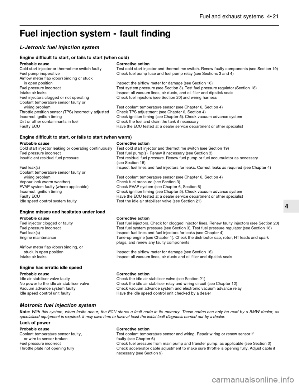
Fuel injection system - fault finding
L-Jetronic fuel injection system
Engine difficult to start, or fails to start (when cold)
Probable cause Corrective action
Cold start injector or thermotime switch faulty Test cold start injector and thermotime switch. Renew faulty components (see Section 19)
Fuel pump inoperative Check fuel pump fuse and fuel pump relay (see Sections 3 and 4)
Airflow meter flap (door) binding or stuck
in open position Inspect the airflow meter for damage (see Section 16)
Fuel pressure incorrect Test system pressure (see Section 3). Test fuel pressure regulator (Section 18)
Intake air leaks Inspect all vacuum lines, air ducts, and oil filler and dipstick seals
Fuel injectors clogged or not operating Check fuel injectors (see Section 20) and wiring harness
Coolant temperature sensor faulty or
wiring problem Test coolant temperature sensor (see Chapter 6, Section 4)
Throttle position sensor (TPS) incorrectly adjusted Check TPS adjustment (see Chapter 6, Section 4)
Incorrect ignition timing Check ignition timing (see Chapter 5). Check vacuum advance system
Dirt or other contaminants in fuel Check the fuel and drain the tank if necessary
Faulty ECU Have the ECU tested at a dealer service department or other specialist
Engine difficult to start, or fails to start (when warm)
Probable cause Corrective action
Cold start injector leaking or operating continuously Test cold start injector and thermotime switch (see Section 19)
Fuel pressure incorrect Test fuel pump(s). Renew if necessary (see Section 3)
Insufficient residual fuel pressure Test residual fuel pressure. Renew fuel pump or fuel accumulator as necessary
(see Section 18)
Fuel leak(s) Inspect fuel lines and fuel injectors for leaks. Correct leaks as required (see Chapter 4)
Coolant temperature sensor faulty or
wiring problem Test coolant temperature sensor (see Chapter 6, Section 4)
Vapour lock (warm weather) Check fuel pressure (see Section 3)
EVAP system faulty (where applicable) Check EVAP system (see Chapter 6, Section 6)
Incorrect ignition timing Check ignition timing (see Chapter 5). Check vacuum advance system
Faulty ECU Have the ECU tested at a dealer service department or other specialist
Idle speed control system faulty Test the idle air stabiliser valve (see Section 21)
Engine misses and hesitates under load
Probable cause Corrective action
Fuel injector clogged or faulty Test fuel injectors. Check for clogged injector lines. Renew faulty injectors (see Section 20)
Fuel pressure incorrect Test fuel system pressure (see Section 3). Test fuel pressure regulator (see Section 18)
Fuel leak(s) Inspect fuel lines and fuel injectors for leaks (see Chapter 4)
Engine maintenance Tune-up engine (see Chapter 1). Check the distributor cap, rotor, HT leads and spark
plugs, and renew any faulty components
Airflow meter flap (door) binding, or
stuck in open position Inspect the airflow meter for damage (see Section 16)
Intake air leaks Inspect all vacuum lines, air ducts and oil filler and dipstick seals
Engine has erratic idle speed
Probable cause Corrective action
Idle air stabiliser valve faulty Check the idle air stabiliser valve (see Section 21)
No power to the idle air stabiliser valve Check the idle air stabiliser relay and wiring circuit (see Chapter 12)
Vacuum advance system faulty Check vacuum advance system and electronic vacuum advance relay
Idle speed control unit faulty Have the idle speed control unit checked by a dealer
Motronic fuel injection system
Note:With this system, when faults occur, the ECU stores a fault code in its memory. These codes can only be read by a BMW dealer, as
specialised equipment is required. It may save time to have at least the initial fault diagnosis carried out by a dealer.
Lack of power
Probable cause Corrective action
Coolant temperature sensor faulty, Test coolant temperature sensor and wiring. Repair wiring or renew sensor if
or wire to sensor broken faulty (see Chapter 6)
Fuel pressure incorrect Check fuel pressure from main pump and transfer pump, as applicable (see Section 3)
Throttle plate not opening fully Check accelerator cable adjustment to make sure throttle is opening fully. Adjust cable if
necessary (see Section 9)
Fuel and exhaust systems 4•21
4
Page 110 of 228
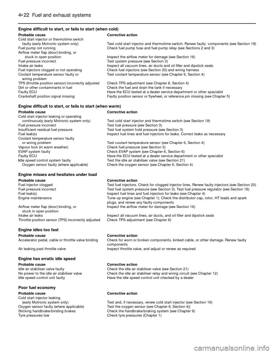
Engine difficult to start, or fails to start (when cold)
Probable cause Corrective action
Cold start injector or thermotime switch
faulty (early Motronic system only) Test cold start injector and thermotime switch. Renew faulty components (see Section 19)
Fuel pump not running Check fuel pump fuse and fuel pump relay (see Sections 2 and 3)
Airflow meter flap (door) binding, or
stuck in open position Inspect the airflow meter for damage (see Section 16)
Fuel pressure incorrect Test system pressure (see Section 3)
Intake air leaks Inspect all vacuum lines, air ducts and oil filler and dipstick seals
Fuel injectors clogged or not operating Check fuel injectors (see Section 20) and wiring harness
Coolant temperature sensor faulty or Test coolant temperature sensor (see Chapter 6, Section 4)
wiring problem
TPS (throttle position sensor) incorrectly adjusted Check TPS adjustment (see Chapter 6, Section 4)
Dirt or other contaminants in fuel Check the fuel and drain the tank if necessary
Faulty ECU Have the ECU tested at a dealer service department or other specialist
Crankshaft position signal missing Faulty position sensor or flywheel, or reference pin missing (see Chapter 5)
Engine difficult to start, or fails to start (when warm)
Probable cause Corrective action
Cold start injector leaking or operating
continuously (early Motronic system only) Test cold start injector and thermotime switch (see Section 19)
Fuel pressure incorrect Test fuel pressure (see Section 3)
Insufficient residual fuel pressure Test fuel system hold pressure (see Section 3)
Fuel leak(s) Inspect fuel lines and fuel injectors for leaks. Correct leaks as necessary
Coolant temperature sensor faulty
or wiring problem Test coolant temperature sensor (see Chapter 6, Section 4)
Vapour lock (in warm weather) Check fuel pressure (see Section 3)
EVAP system faulty Check EVAP system (see Chapter 6, Section 6)
Faulty ECU Have the ECU tested at a dealer service department or other specialist
Idle speed control system faulty Test the idle air stabiliser valve (see Section 21)
Oxygen sensor faulty (where applicable) Check the oxygen sensor (see Chapter 6, Section 4)
Engine misses and hesitates under load
Probable cause Corrective action
Fuel injector clogged Test fuel injectors. Check for clogged injector lines. Renew faulty injectors (see Section 20)
Fuel pressure incorrect Test fuel system pressure (see Section 3). Test fuel pressure regulator (see Section 18)
Fuel leak(s) Inspect fuel lines and fuel injectors for leaks (see Chapter 4)
Engine maintenance Tune-up engine (see Chapter 1). Check the distributor cap, rotor, HT leads and spark
plugs, and renew any faulty components
Airflow meter flap (door) binding, or Inspect the airflow meter for damage (see Section 16)
stuck in open position
Intake air leaks Inspect all vacuum lines, air ducts, and oil filler and dipstick seals
Throttle position sensor (TPS) incorrectly adjusted Check TPS adjustment (see Chapter 6)
Engine idles too fast
Probable cause Corrective action
Accelerator pedal, cable or throttle valve binding Check for worn or broken components, kinked cable, or other damage. Renew faulty
components
Air leaking past throttle valve Inspect throttle valve, and adjust or renew as required
Engine has erratic idle speed
Probable cause Corrective action
Idle air stabiliser valve faulty Check the idle air stabiliser valve (see Section 21)
No power to the idle air stabiliser valve Check the idle air stabiliser relay and wiring circuit (see Chapter 12)
Idle speed control unit faulty Have the idle speed control unit checked by a dealer
Poor fuel economy
Probable cause Corrective action
Cold start injector leaking
(early Motronic system only) Test and, if necessary, renew cold start injector (see Section 19)
Oxygen sensor faulty (where applicable) Test the oxygen sensor (see Chapter 6, Section 4))
Sticking handbrake/binding brakes Check the handbrake/braking system (see Chapter 9)
Tyre pressures low Check tyre pressures (Chapter 1)
4•22 Fuel and exhaust systems
Page 127 of 228
filtered with a flame trap like most
conventional systems. There are no
conventional PCV valves fitted on these
systems - just a hose (see illustration).
3The main components of the PCV system
are the hoses that connect the valve cover to
the throttle body or air cleaner. If abnormal
operating conditions (such as piston ring
problems) arise, the system is designed to
allow excessive amounts of blow-by gases to
flow back through the crankcase vent tube
into the intake system, to be consumed by
normal combustion. Note: Since these
models don’t use a filtering element, it’s a
good idea to check the PCV system
passageways for clogging from sludge and
combustion residue(see illustration).
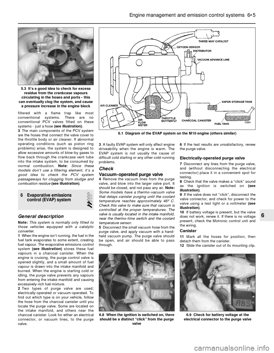
6 Evaporative emissions
control (EVAP) system
2
General description
Note:This system is normally only fitted to
those vehicles equipped with a catalytic
converter.
1When the engine isn’t running, the fuel in the
fuel tank evaporates to some extent, creating
fuel vapour. The evaporative emissions control
system (see illustration)stores these fuel
vapours in a charcoal canister. When the
engine is cruising, the purge control valve is
opened slightly, and a small amount of fuel
vapour is drawn into the intake manifold and
burned. When the engine is starting cold or
idling, the purge valve prevents any vapours
from entering the intake manifold and causing
excessively-rich fuel mixture.
2Two types of purge valve are used;
electrically-operated or vacuum-operated. To
find out which type is on your vehicle, follow
the hose from the charcoal canister until you
locate the purge valve. Some are located on
the intake manifold, and others near the
charcoal canister. Look for either an electrical
connector, or vacuum lines, to the purge
valve.3A faulty EVAP system will only affect engine
driveability when the engine is warm. The
EVAP system is not usually the cause of
difficult cold starting or any other cold-running
problems.
Check
Vacuum-operated purge valve
4Remove the vacuum lines from the purge
valve, and blow into the larger valve port. It
should be closed, and not pass any air. Note:
Some models have a thermo-vacuum valve
that delays canister purging until the coolant
temperature reaches approximately 46º C.
Check this valve to make sure that vacuum is
controlled at the proper temperatures. The
valve is usually located in the intake manifold,
near the thermo-time switch and the coolant
temperature sensor.
5Disconnect the small vacuum hose from the
purge valve, and apply vacuum with a hand-
held vacuum pump. The purge valve should
be open, and air should be able to pass
through.6If the test results are unsatisfactory, renew
the purge valve.
Electrically-operated purge valve
7Disconnect any lines from the purge valve,
and (without disconnecting the electrical
connector) place it in a convenient spot for
testing.
8Check that the valve makes a “click” sound
as the ignition is switched on (see
illustration).
9If the valve does not “click”, disconnect the
valve connector, and check for power to the
valve using a test light or a voltmeter (see
illustration).
10If battery voltage is present, but the valve
does not work, renew it. If there is no voltage
present, check the Motronic control unit and
the wiring.
Canister
11Mark all the hoses for position, then
detach them from the canister.
12Slide the canister out of its mounting clip.
Engine management and emission control systems 6•5
6.1 Diagram of the EVAP system on the M10 engine (others similar)
6.9 Check for battery voltage at the
electrical connector to the purge valve6.8 When the ignition is switched on, there
should be a distinct “click” from the purge
valve
6
5.3 It’s a good idea to check for excess
residue from the crankcase vapours
circulating in the hoses and ports - this
can eventually clog the system, and cause
a pressure increase in the engine block
Page 174 of 228
13 Headlights- adjustment
2
Note:The headlights must be aimed correctly.
If adjusted incorrectly, they could momentarily
blind the driver of an oncoming vehicle and
cause a serious accident, or seriously reduce
your ability to see the road. The headlights
should be checked for proper aim every
12 months (as is done during the MOT test),
and any time a new headlight is fitted or front-
end body work is performed. It should be
emphasised that the following procedure will
only provide a temporary setting until the
headlights can be adjusted by a properly-
equipped garage.
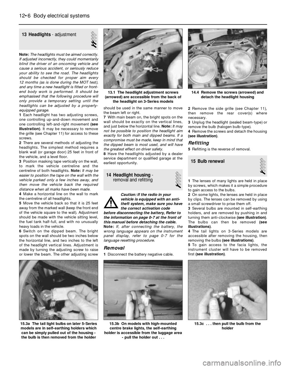
1Each headlight has two adjusting screws,
one controlling up-and-down movement and
one controlling left-and-right movement (see
illustration). It may be necessary to remove
the grille (see Chapter 11) for access to these
screws.
2There are several methods of adjusting the
headlights. The simplest method requires a
blank wall (or garage door) 25 feet in front of
the vehicle, and a level floor.
3Position masking tape vertically on the wall,
to mark the vehicle centreline and the
centreline of both headlights. Note:It may be
easier to position the tape on the wall with the
vehicle parked only a few inches away, and
then move the vehicle back the required
distance when all marks have been made.
4Make a horizontal line on the wall to mark
the centreline of all headlights.
5Move the vehicle back so that it is 25 feet
away from the marked wall (keep the front end
of the vehicle square to the wall). Adjustment
should be made with the vehicle sitting level,
the fuel tank half-full, and with no unusually
heavy loads in the vehicle.
6Switch on the dipped beam. The bright
spots on the wall should be two inches below
the horizontal line, and two inches to the left
of the headlight vertical lines. Adjustment is
made by turning the adjusting screw to raise
or lower the beam. The other adjusting screwshould be used in the same manner to move
the beam left or right.
7With main beam on, the bright spots on the
wall should be exactly on the vertical lines,
and just below the horizontal line. Note:It may
not be possible to position the headlight aim
exactly for both main and dipped beams. If a
compromise must be made, keep in mind that
the dipped beam is most used, and will have
the greatest effect on driver safety.
8Have the headlights adjusted by a dealer
service department or qualified garage at the
earliest opportunity.
14 Headlight housing-
removal and refitting
1
Caution: If the radio in your
vehicle is equipped with an anti-
theft system, make sure you have
the correct activation code
before disconnecting the battery, Refer to
the information on page 0-7 at the front of
this manual before detaching the cable.
Note: If, after connecting the battery, the
wrong language appears on the instrument
panel display, refer to page 0-7 for the
language resetting procedure.
Removal
1Disconnect the battery negative cable.2Remove the side grille (see Chapter 11),
then remove the rear cover(s) where
necessary.
3Unplug the headlight (sealed beam-type) or
remove the bulb (halogen bulb-type).
4Remove the screws and detach the housing
(see illustration).
Refitting
5Refitting is the reverse of removal.
15 Bulb renewal
1
1The lenses of many lights are held in place
by screws, which makes it a simple procedure
to gain access to the bulbs.
2On some lights, the lenses are held in place
by clips. The lenses can be removed by using
a small screwdriver to prise them off.
3Several bulbs are mounted in self-earthing
holders, and are removed by pushing in and
turning them anti-clockwise (see illustration).
The bulbs can then be removed (see
illustrations).
4The tail lights on 3-Series models are
accessible after removing the housing, then
removing the bulbs (see illustrations).
5To gain access to the facia lights, the
instrument cluster will have to be removed
first (see illustration).
12•6 Body electrical systems
15.3c . . . then pull the bulb from the
holder15.3b On models with high-mounted
centre brake lights, the self-earthing
holder is accessible from the luggage area
- pull the holder out . . .15.3a The tail light bulbs on later 5-Series
models are in self-earthing holders which
can be simply pulled out of the housing -
the bulb is then removed from the holder
14.4 Remove the screws (arrowed) and
detach the headlight housing13.1 The headlight adjustment screws
(arrowed) are accessible from the back of
the headlight on 3-Series models
Page 213 of 228
REF•12Fault Finding
Fuel system
Excessive fuel consumption
m mDirty or clogged air filter element (Chapter 1).
m mIgnition timing incorrect (Chapter 5).
m mEmissions system not functioning properly (Chapter 6).
m mFuel injection internal parts or carburettor jets excessively worn or
damaged (Chapter 4).
m mLow tyre pressure or incorrect tyre size (Chapter 1).
m mUnsympathetic driving style, or unfavourable conditions.
Fuel leakage and/or fuel odour
Warning: Don’t drive the vehicle if a fuel leak is
suspected. Leaking fuel in the engine compartment
could catch fire.
m mLeak in a fuel feed or vent line (Chapter 4).
m mTank overfilled.
m mFuel injector or carburettor parts excessively worn, or fuel system
gaskets leaking (Chapter 4).
Cooling system
Overheating
m mInsufficient coolant in system (Chapter 1).
m mWater pump drivebelt defective or out of adjustment (Chapter 1).
m mRadiator matrix blocked, or grille restricted (Chapter 3).
m mThermostat faulty (Chapter 3).
m mRadiator cap not maintaining proper pressure (Chapter 3).
m mIgnition timing incorrect (Chapter 5).
Overcooling
m
mFaulty thermostat (Chapter 3).
External coolant leakage
m
mDeteriorated/damaged hoses; loose clamps (Chapters 1 and 3).
m mWater pump seal defective (Chapters 1 and 3).
m mLeakage from radiator matrix, heater matrix or header tank
(Chapter 3).
m mRadiator/engine block drain plugs or water jacket core plugs
leaking (Chapters 2 and 3).
Internal coolant leakage
m mLeaking cylinder head gasket (Chapter 2).
m mCracked cylinder bore or cylinder head (Chapter 2).
Coolant loss
m
mToo much coolant in system (Chapter 1).
m mCoolant boiling away because of overheating (see above).
m mInternal or external leakage (see above).
m mFaulty radiator cap (Chapter 3).
Poor coolant circulation
m
mInoperative water pump (Chapter 3).
m mRestriction in cooling system (Chapters 1 and 3).
m mWater pump drivebelt defective/out of adjustment (Chapter 1).
m mThermostat sticking (Chapter 3).
Clutch
Pedal travels to floor - no pressure or very little
resistance
m mMaster or slave cylinder faulty (Chapter 8).
m mFluid line burst or leaking (Chapter 8).
m mConnections leaking (Chapter 8).
m mNo fluid in reservoir (Chapter 1).
m mIf fluid is present in master cylinder dust cover, master cylinder rear
seal has failed (Chapter 8).
m mBroken release bearing or fork (Chapter 8).
Fluid in area of master cylinder dust cover, and on
pedal
m mRear seal failure in master cylinder (Chapter 8).
Fluid on slave cylinder
m
mSlave cylinder plunger seal faulty (Chapter 8).
Pedal feels “spongy” when depressed
m
mAir in system (Chapter 8).
Unable to select gears
m
mFaulty transmission (Chapter 7).
m mFaulty clutch plate (Chapter 8).
m mFork and bearing not assembled properly (Chapter 8).
m mFaulty pressure plate (Chapter 8).
m mPressure plate-to-flywheel bolts loose (Chapter 8).
Clutch slips (engine speed increases with no
increase in vehicle speed)
m mClutch plate worn (Chapter 8).
m mClutch plate is oil-soaked by leaking rear main seal (Chapter 8).
m mWarped pressure plate or flywheel (Chapter 8).
m mWeak diaphragm spring (Chapter 8).
m mClutch plate overheated.
Grabbing (chattering) as clutch is engaged
m
mOil on clutch plate lining, burned or glazed facings (Chapter 8).
m mWorn or loose engine or transmission mountings (Chapters 2
and 7A).
m mWorn splines on clutch plate hub (Chapter 8).
m mWarped pressure plate or flywheel (Chapter 8).
Noise in clutch area
m
mFork improperly fitted (Chapter 8).
m mFaulty release bearing (Chapter 8).
Clutch pedal stays on floor
m
mFork binding in housing (Chapter 8).
m mBroken release bearing or fork (Chapter 8).
High pedal effort
m
mFork binding in housing (Chapter 8).
m mPressure plate faulty (Chapter 8).
m mIncorrect-size master or slave cylinder fitted (Chapter 8).
Page 218 of 228
REF•18Automotive chemicals and lubricants
A number of automotive chemicals and
lubricants are available for use during vehicle
maintenance and repair. They include a wide
variety of products ranging from cleaning
solvents and degreasers to lubricants and
protective sprays for rubber, plastic and
vinyl.
Cleaners
Carburettor cleaner and choke cleaner
is a strong solvent for gum, varnish and
carbon. Most carburettor cleaners leave a
dry-type lubricant film which will not harden or
gum up. Because of this film, it is not
recommended for use on electrical
components.
Brake system cleaneris used to remove
grease and brake fluid from the brake system,
where clean surfaces are absolutely
necessary. It leaves no residue, and often
eliminates brake squeal caused by
contaminants.
Electrical cleaner removes oxidation,
corrosion and carbon deposits from electrical
contacts, restoring full current flow. It can also
be used to clean spark plugs, carburettor jets,
voltage regulators and other parts where an
oil-free surface is desired.
Moisture dispersantsremove water and
moisture from electrical components such as
alternators, voltage regulators, electrical
connectors and fuse blocks. They are non-
conductive and non-corrosive.
Degreasersare heavy-duty solvents used
to remove grease from the outside of the
engine and from chassis components. They
can be sprayed or brushed on, and are usually
rinsed off with water.
Lubricants
Engine oilis the lubricant formulated for
use in engines. It normally contains a wide
variety of additives to prevent corrosion and
reduce foaming and wear. Engine oil comes in
various weights (viscosity ratings) from 5 to
60. The recommended weight of the oil
depends on the season, temperature and the
demands on the engine. Light oil is used in
cold climates and under light load conditions.
Heavy oil is used in hot climates, and where
high loads are encountered. Multi-viscosity
(multigrade) oils are designed to have
characteristics of both light and heavy oils,
and are available in a number of weights from
5W-20 to 20W-50.
Gear oilis designed to be used in
differentials, manual transmissions and other
areas where high-temperature lubrication is
required.
Chassis and wheel bearing greaseis a
heavy grease used where increased loads and
friction are encountered, such as for wheel
bearings, balljoints, tie-rod ends and universal
joints.High-temperature wheel bearing grease
is designed to withstand the extreme
temperatures encountered by wheel bearings
in disc brake-equipped vehicles. It usually
contains molybdenum disulphide (moly),
which is a dry-type lubricant.
White greaseis a heavy grease for metal-
to-metal applications where water is a
problem. White grease stays soft at both low
and high temperatures, and will not wash off
or dilute in the presence of water.
Assembly lubeis a special extreme-
pressure lubricant, usually containing moly,
used to lubricate high-load parts (such as
main and rod bearings and cam lobes) for
initial start-up of a new engine. The assembly
lube lubricates the parts without being
squeezed out or washed away until the engine
oiling system begins to function.
Silicone lubricants are used to protect
rubber, plastic, vinyl and nylon parts.
Graphite lubricantsare used where oils
cannot be used due to contamination
problems, such as in locks. The dry graphite
will lubricate metal parts while remaining
uncontaminated by dirt, water, oil or acids. It
is electrically conductive, and will not foul
electrical contacts in locks such as the
ignition switch.
Penetrating oilsloosen and lubricate
frozen, rusted and corroded fasteners and
prevent future rusting or freezing.
Heat-sink greaseis a special electrically
non-conductive grease that is used for
mounting electronic ignition modules where it
is essential that heat is transferred away from
the module.
Sealants
RTV sealantis one of the most widely-
used gasket compounds. Made from silicone,
RTV is air-curing; it seals, bonds, waterproofs,
fills surface irregularities, remains flexible,
doesn’t shrink, is relatively easy to remove,
and is used as a supplementary sealer with
almost all low- and medium-temperature
gaskets.
Anaerobic sealantis much like RTV in that
it can be used either to seal gaskets or to form
gaskets by itself. It remains flexible, is solvent-
resistant, and fills surface imperfections. The
difference between an anaerobic sealant and
an RTV-type sealant is in the curing. RTV
cures when exposed to air, while an anaerobic
sealant cures only in the absence of air. This
means that an anaerobic sealant cures only
after the assembly of parts, sealing them
together.
Thread and pipe sealant is used for
sealing hydraulic and pneumatic fittings and
vacuum lines. It is usually made from a Teflon
compound, and comes in a spray, a paint-on
liquid and as a wrap-around tape.
Chemicals
Anti-seize compoundprevents seizing,
chafing, cold welding, rust and corrosion in
fasteners. High-temperature anti-seize,
usually made with copper and graphite
lubricants, is used for exhaust system and
exhaust manifold bolts.
Anaerobic locking compoundsare used
to keep fasteners from vibrating or working
loose, and cure only after installation, in the
absence of air. Medium-strength locking
compound is used for small nuts, bolts and
screws that may be removed later. High-
strength locking compound is for large nuts,
bolts and studs which aren’t removed on a
regular basis.
Oil additivesrange from viscosity index
improvers to chemical treatments that claim
to reduce internal engine friction. It should be
noted that most oil manufacturers caution
against using additives with their oils.
Fuel additivesperform several functions,
depending on their chemical make-up. They
usually contain solvents that help dissolve
gum and varnish that build up on carburettor,
fuel injection and intake parts. They also serve
to break down carbon deposits that form on
the inside surfaces of the combustion
chambers. Some additives contain upper
cylinder lubricants for valves and piston rings,
and others contain chemicals to remove
condensation from the fuel tank.
Miscellaneous
Brake fluidis specially-formulated
hydraulic fluid that can withstand the heat and
pressure encountered in brake systems. It is
poisonous and inflammable. Care must be
taken so this fluid does not come in contact
with painted surfaces or plastics. An opened
container should always be resealed, to
prevent contamination by water or dirt. Brake
fluid absorbs moisture from the air, if left in an
unsealed container.
Weatherstrip adhesiveis used to bond
weatherstripping around doors, windows and
boot lids. It is sometimes used to attach trim
pieces.
Undersealis a petroleum-based, tar-like
substance that is designed to protect metal
surfaces on the underside of the vehicle from
corrosion. It also acts as a sound-deadening
agent by insulating the bottom of the vehicle.
Waxes and polishesare used to help
protect painted and plated surfaces from the
weather. Different types of paint may require
the use of different types of wax and polish.
Some polishes utilise a chemical or abrasive
cleaner to help remove the top layer of
oxidised (dull) paint on older vehicles. In
recent years, many non-wax polishes
containing a wide variety of chemicals such as
polymers and silicones have been introduced.
These non-wax polishes are usually easier to
apply, and last longer than conventional
waxes and polishes.
Page 226 of 228
REF•26Index
E
Earth check - 12•2
Electric fan - 3•4
Electric shock - 0•5
Electric windows - 12•9
Electrical equipment - REF•2
Electrical system fault finding - 12•1
Electronic control system - 4•3, 4•14
Electronic control unit (ECU) - 6•1
Engine fault finding - REF•10
Engine tune-up - 1•7
Engine electrical systems- 5•1et seq
Engine electrical systems fault finding -
REF•11
Engine management and emission control
systems- 6•1et seq
Engine oil - 1•3, 1•7, 1•11
Environmental considerations - REF•8
Evaporative emissions control (EVAP)
system - 1•26, 6•5
Evaporator - 3•10
Exhaust emission checks - REF•4
Exhaust manifold - 2A•6
Exhaust system - 1•21, 4•20, REF•3
F
Fan - 3•4, 3•5
Fault finding- REF•9et seq
Fault finding - automatic transmission -
7B•2, REF•13
Fault finding - braking system - REF•14
Fault finding - clutch - REF•12
Fault finding - cooling system - REF•12
Fault finding - electrical system - 12•1,
REF•11
Fault finding - engine - REF•10
Fault finding - fuel system - 4•21, REF•12
Fault finding - manual transmission -
REF•13
Fault finding - suspension and steering -
REF•15
Filling - 11•3
Final drive - 8•2, 8•10, 8•11
Final drive oil - 1•3, 1•19, 1•26
Fire - 0•5
Flexible coupling - 8•7
Fluid level checks - 1•7
Fluid seals - 7B•5
Flywheel - 2A•18
Fuel and exhaust systems- 1•20, 4•1et
seq,REF•4
Fuel system fault finding - REF•12
Fuel filter - 1•25
Fuel hoses - 1•14
Fuel injection system - 4•3, 4•14
Fuel injection system - fault finding - 4•21
Fuel injectors - 4•18
Fuel level sender unit - 4•5, 4•6
Fuel lines and fittings - 4•7
Fuel pressure - 4•3
Fuel pressure regulator - 4•16
Fuel pump - 4•3, 4•4, 4•5
Fuel tank - 4•7, 4•8
Fume or gas intoxication - 0•5
Fuses - 12•2
G
Gaiters - 1•22, 8•9, 10•13
Gashes in bodywork - 11•2
Gaskets - REF•8
Gear lever - 7A•1
Gearbox - SeeManual transmission
Gearbox oil - 1•3, 1•19, 1•25
General engine overhaul procedures-
2B•1et seq
Glass - 11•4, 11•8
Glossary of technical terms - REF•20
Grille - 11•4
H
Handbrake - 1•23, 9•2, 9•12, REF•1
Handbrake fault - REF•14
Handles - 11•8
Hazard warning flasher - 12•2
HC emissions - REF•4
Headlights - 12•3, 12•5, 12•6
Heated rear window - 12•8
Heater - 3•2, 3•7, 3•8
Hinges - 11•4
HT leads - 1•18
Hubs - 10•8, 10•11, REF•3
Hydraulic servo - 9•11
Hydraulic tappets - 2B•11
Hydrofluoric acid - 0•5
I
Idle air stabiliser valve - 4•18
Idle speed adjustment - 1•15
Ignition coil - 5•5
Ignition control unit - 5•6, 5•7
Ignition sensors - 5•8
Ignition switch - 12•3
Ignition system - 5•3
Ignition timing - 5•4
Ignition timing sensors - 6•4
Impulse generator - 5•6, 5•7
In-car engine repair procedures- 2A•1et
seq
Indicators - 12•2, 12•3
Information sensors - 6•2
Injectors - 4•18
Input shaft - 7A•2
Instrument cluster - 12•4
Instrument panel language display - 0•7
Intake manifold - 2A•4
Intermediate shaft - 2A•12, 2B•14, 2B•19
Introduction to the BMW 3- and 5-Series -
0•4
J
Jacking - 0•8
Joint mating faces - REF•8
Jump starting - 0•9
K
Kickdown cable - 7B•3
L
L-Jetronic fuel injection system - 4•14,
4•19
Language display - 0•7
Latch - 11•8
Leaks - 0•10, 7B•3, REF•12, REF•13
Locknuts, locktabs and washers - REF•8
Locks - 11•4, 11•8
Lubricants - REF•18
M
Main bearings - 2B•17, 2B•19
Manifolds - 2A•4, 2A•6
Manual transmission- 7A•1et seq
Manual transmission fault finding - REF•13
Manual transmission oil - 1•3, 1•19, 1•25
Master cylinder - 8•3, 9•9
Mechanical fan - 3•4, 3•5
Mirrors - 11•8, REF•1
Misfire - REF•11
Mixture - REF•4
MOT test checks- REF•1 et seq
Motronic engine management system -
6•1
Motronic fuel injection system - 4•14, 4•19
Mountings - 2A•19, 7A•3
O
Oil - differential - 1•19, 1•26
Oil - engine - 1•3, 1•7, 1•11
Oil - final drive - 1•3
Oil - manual transmission - 1•3, 1•19, 1•25
Oil filter - 1•11, 1•12
Oil pump - 2A•16
Oil seals - 2A•12, 2A•13, 2A•19, 2B•20,
7A•2, 7B•5, 8•10, 8•12, REF•8
Open-circuit - 12•2
Output shaft - 7A•2, 7B•5
Overcooling - REF•12
Overheating - REF•12
Oxygen sensor - 6•2
P
Pads - 9•2, 9•3
Pedals - 8•3, 9•13
Pinion oil - 8•12
Pinking - REF•11
Piston rings - 2B•18
Pistons - 2B•12, 2B•16, 2B•21
Plastic components - 11•3
Poisonous or irritant substances - 0•5
Position sensors - 5•8
Positive crankcase ventilation (PCV)
system - 6•4
Power steering - 1•14, 10•15, 10•16
Power steering fluid - 1•12
Propeller shaft - 8•2, 8•6, 8•8
Pulse sensor - 5•8
Purge valve - 6•5