manual BMW 3 SERIES 1988 E30 User Guide
[x] Cancel search | Manufacturer: BMW, Model Year: 1988, Model line: 3 SERIES, Model: BMW 3 SERIES 1988 E30Pages: 228, PDF Size: 7.04 MB
Page 19 of 228
inhibitors wear out, so it must be renewed at
the specified intervals.
Brake and clutch fluid
Warning: Brake fluid can harm
your eyes and damage painted
surfaces, so use extreme caution
when handling or pouring it. Do
not use brake fluid that has been standing
open or is more than one year old. Brake
fluid absorbs moisture from the air, which
can cause a dangerous loss of brake
effectiveness. Use only the specified type
of brake fluid. Mixing different types (such
as DOT 3 or 4 and DOT 5) can cause brake
failure.
14The brake master cylinder is mounted at
the left rear corner of the engine
compartment. The clutch fluid reservoir
(manual transmission models) is mounted on
the right-hand side.
15To check the clutch fluid level, observe
the level through the translucent reservoir.
The level should be at or near the step
moulded into the reservoir. If the level is low,
remove the reservoir cap to add the specified
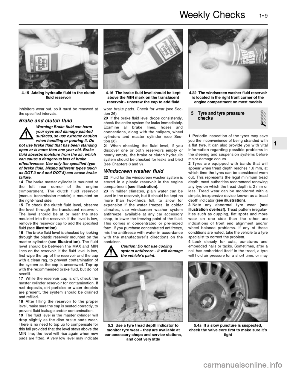
fluid (see illustration).
16The brake fluid level is checked by looking
through the plastic reservoir mounted on the
master cylinder (see illustration). The fluid
level should be between the MAX and MIN
lines on the reservoir. If the fluid level is low,
first wipe the top of the reservoir and the cap
with a clean rag, to prevent contamination of
the system as the cap is unscrewed. Top-up
with the recommended brake fluid, but do not
overfill.
17While the reservoir cap is off, check the
master cylinder reservoir for contamination. If
rust deposits, dirt particles or water droplets
are present, the system should be drained
and refilled.
18After filling the reservoir to the proper
level, make sure the cap is seated correctly, to
prevent fluid leakage and/or contamination.
19The fluid level in the master cylinder will
drop slightly as the disc brake pads wear.
There is no need to top up to compensate for
this fall provided that the level stays above the
MIN line; the level will rise again when new
pads are fitted. A very low level may indicateworn brake pads. Check for wear (see Sec-
tion 26).
20If the brake fluid level drops consistently,
check the entire system for leaks immediately.
Examine all brake lines, hoses and
connections, along with the calipers, wheel
cylinders and master cylinder (see Sec-
tion 26).
21When checking the fluid level, if you
discover one or both reservoirs empty or
nearly empty, the brake or clutch hydraulic
system should be checked for leaks and bled
(see Chapters 8 and 9).
Windscreen washer fluid
22Fluid for the windscreen washer system is
stored in a plastic reservoir in the engine
compartment (see illustration).
23In milder climates, plain water can be
used in the reservoir, but it should be kept no
more than two-thirds full, to allow for
expansion if the water freezes. In colder
climates, use windscreen washer system
antifreeze, available at any car accessory
shop, to lower the freezing point of the fluid.
This comes in concentrated or pre-mixed
form. If you purchase concentrated antifreeze,
mix the antifreeze with water in accordance
with the manufacturer’s directions on the
container.
Caution: Do not use cooling
system antifreeze - it will damage
the vehicle’s paint.
5 Tyre and tyre pressure
checks
1
1Periodic inspection of the tyres may save
you the inconvenience of being stranded with
a flat tyre. It can also provide you with vital
information regarding possible problems in
the steering and suspension systems before
major damage occurs.
2Tyres are equipped with bands that will
appear when tread depth reaches 1.6 mm, at
which time the tyres can be considered worn
out. This represents the legal minimum tread
depth; most authorities recommend renewing
any tyre on which the tread depth is 2 mm or
less. Tread wear can be monitored with a
simple, inexpensive device known as a tread
depth indicator (see illustration).
3Note any abnormal tyre wear (see
illustration overleaf). Tread pattern irregular-
ities such as cupping, flat spots and more
wear on one side than the other are
indications of front end alignment and/or
wheel balance problems. If any of these
conditions are noted, take the vehicle to a tyre
specialist to correct the problem.
4Look closely for cuts, punctures and
embedded nails or tacks. Sometimes, after a
nail has embedded itself in the tread, a tyre
will hold air pressure for a short time, or may
1•9
4.22 The windscreen washer fluid reservoir
is located in the right front corner of the
engine compartment on most models4.16 The brake fluid level should be kept
above the MIN mark on the translucent
reservoir - unscrew the cap to add fluid4.15 Adding hydraulic fluid to the clutch
fluid reservoir
5.4a If a slow puncture is suspected,
check the valve core first to make sure it’s
tight5.2 Use a tyre tread depth indicator to
monitor tyre wear - they are available at
car accessory shops and service stations,
and cost very little
1
Weekly Checks
Page 23 of 228
Caution: Do not overfill the
reservoir. If too much fluid is
added, remove the excess with a
clean syringe. Refit the cap.
7If frequent topping-up is needed, check the
power steering hoses and connections for
leaks and wear (see Section 10).
8Check the condition and tension of the
drivebelt (see Section 11).
8 Automatic transmission fluid
level check
1
Caution: The use of transmission
fluid other than the type listed in
this Chapter’s Specifications
could result in transmission
malfunctions or failure.
1The automatic transmission fluid should be
carefully maintained. Low fluid level can lead
to slipping or loss of drive, while overfilling
can cause foaming and loss of fluid. Either
condition can cause transmission damage.
2Since transmission fluid expands as it heats
up, the fluid level should only be checked
when the transmission is warm (at normal
operating temperature). If the vehicle has just
been driven over 20 miles (32 km), the
transmission can be considered warm. You
can also check the fluid level when the
transmission is cold. If the vehicle has not
been driven for over five hours and the fluid is
about room temperature (20°C), the
transmission is cold. However, the fluid level
is normally checked with the transmission
warm, to ensure accurate results.
Caution: If the vehicle has just
been driven for a long time at
high speed or in city traffic, in hot
weather, or if it has been pulling
a trailer, an accurate fluid level reading
cannot be obtained. Allow the trans-
mission to cool down for about 30 minutes.
3Immediately after driving the vehicle, park it
on a level surface, apply the handbrake and
start the engine. While the engine is idling,
depress the brake pedal and move theselector lever through all the gear ranges,
beginning and ending in Park.
4The automatic transmission dipstick tube is
located in the left rear corner of the engine
compartment.
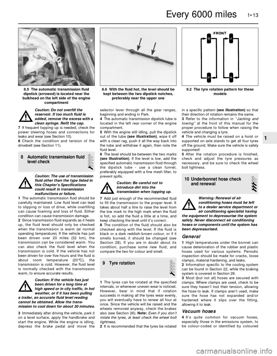
5With the engine still idling, pull the dipstick
out of the tube (see illustration), wipe it off
with a clean rag, push it all the way back into
the tube and withdraw it again, then note the
fluid level.
6The level should be between the two marks
(see illustration). If the level is low, add the
specified automatic transmission fluid through
the dipstick tube - use a clean funnel,
preferably equipped with a fine mesh filter, to
prevent spills.
Caution: Be careful not to
introduce dirt into the
transmission when topping up.
7Add just enough of the recommended fluid
to fill the transmission to the proper level. It
takes about half a litre to raise the level from
the low mark to the high mark when the fluid
is hot, so add the fluid a little at a time, and
keep checking the level until it’s correct.
8The condition of the fluid should also be
checked along with the level. If the fluid is
black or a dark reddish-brown colour, or if it
smells burned, it should be changed (see
Section 28). If you are in doubt about its
condition, purchase some new fluid, and
compare the two for colour and smell.
9 Tyre rotation
1
1The tyres can be rotated at the specified
intervals, or whenever uneven wear is noticed.
However, bear in mind that if rotation
succeeds in making all the tyres wear evenly,
you will eventually have to renew all four at
once. Since the vehicle will be raised and the
wheels removed anyway, check the brakes
also (see Section 26). Note: Even if you don’t
rotate the tyres, at least check the wheel bolt
tightness.
2It is recommended that the tyres be rotatedin a specific pattern (see illustration)so that
their direction of rotation remains the same.
3Refer to the information in “Jacking and
towing”at the front of this manual for the
proper procedure to follow when raising the
vehicle and changing a tyre.
4The vehicle must be raised on a hoist or
supported on axle stands to get all four tyres
off the ground. Make sure the vehicle is safely
supported!
5After the rotation procedure is finished,
check and adjust the tyre pressures as
necessary, and be sure to check the wheel
bolt tightness.
10 Underbonnet hose check
and renewal
3
Warning: Renewal of air
conditioning hoses must be left
to a dealer service department or
air conditioning specialist having
the equipment to depressurise the system
safely. Never disconnect air conditioning
hoses or components until the system has
been depressurised.
General
1High temperatures under the bonnet can
cause deterioration of the rubber and plastic
hoses used for various systems. Periodic
inspection should be made for cracks, loose
clamps, material hardening, and leaks.
2Information specific to the cooling system
can be found in Section 22, while the braking
system is covered in Section 26.
3Most (but not all) hoses are secured with
clamps. Where clamps are used, check to be
sure they haven’t lost their tension, allowing
the hose to leak. If clamps aren’t used, make
sure the hose has not expanded and/or
hardened where it slips over the fitting,
allowing it to leak.
Vacuum hoses
4It’s quite common for vacuum hoses,
especially those in the emissions system, to
be colour-coded or identified by coloured
1•13
9.2 The tyre rotation pattern for these
models8.6 With the fluid hot, the level should be
kept between the two dipstick notches,
preferably near the upper one8.5 The automatic transmission fluid
dipstick (arrowed) is located near the
bulkhead on the left side of the engine
compartment
1
Every 6000 miles
Page 25 of 228
move the component away from the engine to
tighten the belt, or towards the engine to
loosen the belt. Hold the accessory in
position, and check the belt tension. If it is
correct, tighten the two bolts until just tight,
then recheck the tension. If the tension is still
correct, tighten the bolts.
8It will often be necessary to use some sort
of lever to move the accessory while the belt
is adjusted. If this must be done to gain the
proper leverage, be very careful not to
damage the component being moved, or the
part being prised against.
Renewal
9To renew a belt, follow the instructions
above for adjustment, but remove the belt
from the pulleys.
10In some cases, you will have to remove
more than one belt, because of their
arrangement on the front of the engine.
Because of this, and the fact that belts will
tend to fail at the same time, it is wise to
renew all belts together. Mark each belt and
its appropriate pulley groove, so all renewed
belts can be fitted in their proper positions.
11It is a good idea to take the old belts with
you when buying new ones, in order to make
a direct comparison for length, width and
design.
12Recheck the tension of new belts after a
few hundred miles.
12 Engine idle speed and CO
level check and adjustment
4
Note:The engine should be at normal
operating temperature, with correct ignition
timing and valve clearances (where
adjustable). The air filter should be in good
condition, and all electrical components
(including the air conditioning, where fitted)
should be switched off.
Carburettor
1Connect a tachometer and exhaust gas
analyser (CO meter) to the engine.
2Start the engine and allow it to idle.
3Check that the idle speed is as given in the
Specifications. Adjustment of the idle speed is
only possible on the 2B4 carburettor. Turn the
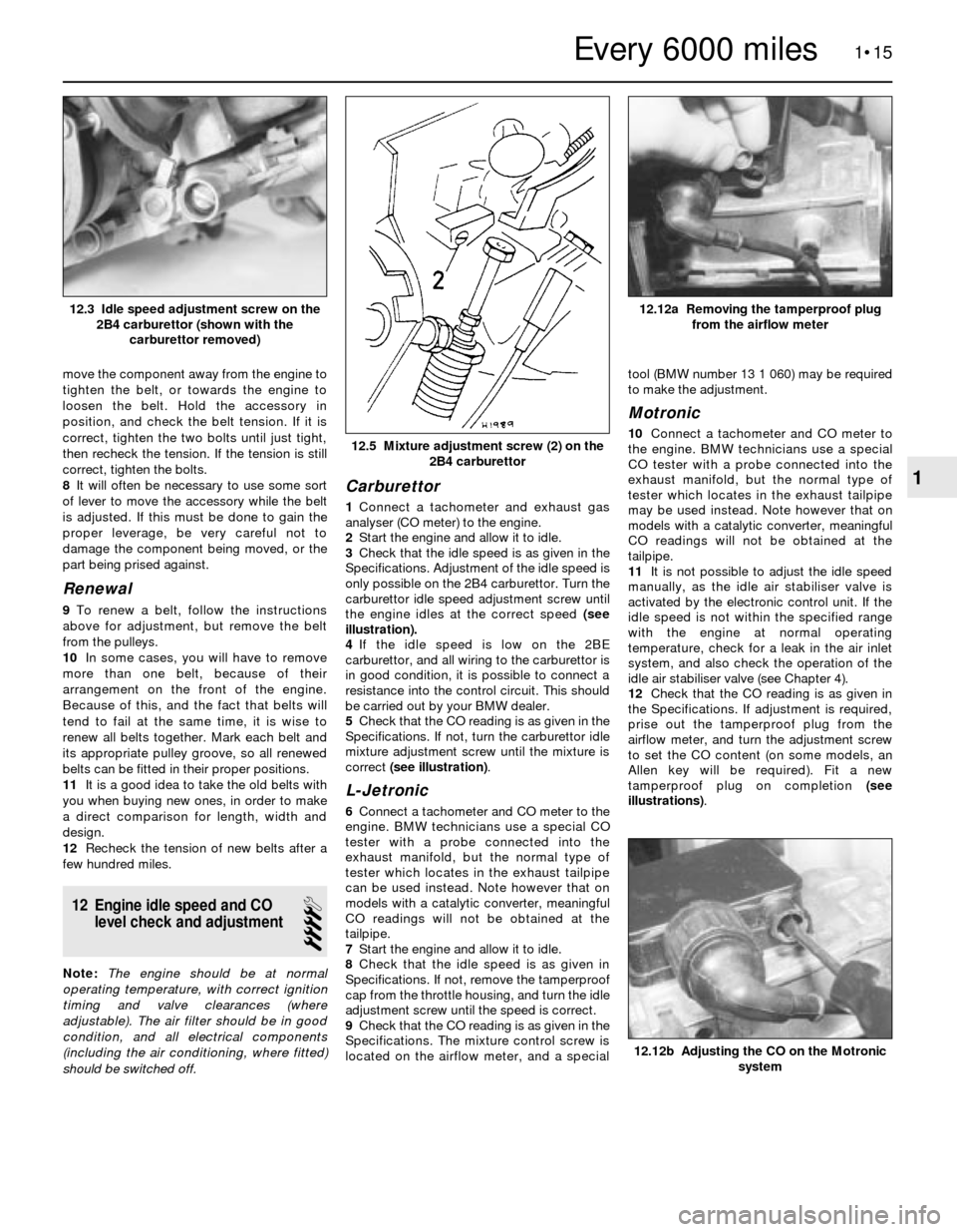
carburettor idle speed adjustment screw until
the engine idles at the correct speed (see
illustration).
4If the idle speed is low on the 2BE
carburettor, and all wiring to the carburettor is
in good condition, it is possible to connect a
resistance into the control circuit. This should
be carried out by your BMW dealer.
5Check that the CO reading is as given in the
Specifications. If not, turn the carburettor idle
mixture adjustment screw until the mixture is
correct (see illustration).
L-Jetronic
6Connect a tachometer and CO meter to the
engine. BMW technicians use a special CO
tester with a probe connected into the
exhaust manifold, but the normal type of
tester which locates in the exhaust tailpipe
can be used instead. Note however that on
models with a catalytic converter, meaningful
CO readings will not be obtained at the
tailpipe.
7Start the engine and allow it to idle.
8Check that the idle speed is as given in
Specifications. If not, remove the tamperproof
cap from the throttle housing, and turn the idle
adjustment screw until the speed is correct.
9Check that the CO reading is as given in the
Specifications. The mixture control screw is
located on the airflow meter, and a specialtool (BMW number 13 1 060) may be required
to make the adjustment.
Motronic
10Connect a tachometer and CO meter to
the engine. BMW technicians use a special
CO tester with a probe connected into the
exhaust manifold, but the normal type of
tester which locates in the exhaust tailpipe
may be used instead. Note however that on
models with a catalytic converter, meaningful
CO readings will not be obtained at the
tailpipe.
11It is not possible to adjust the idle speed
manually, as the idle air stabiliser valve is
activated by the electronic control unit. If the
idle speed is not within the specified range
with the engine at normal operating
temperature, check for a leak in the air inlet
system, and also check the operation of the
idle air stabiliser valve (see Chapter 4).
12Check that the CO reading is as given in
the Specifications. If adjustment is required,
prise out the tamperproof plug from the
airflow meter, and turn the adjustment screw
to set the CO content (on some models, an
Allen key will be required). Fit a new
tamperproof plug on completion (see
illustrations).
1•15
12.12a Removing the tamperproof plug
from the airflow meter
12.5 Mixture adjustment screw (2) on the
2B4 carburettor
12.3 Idle speed adjustment screw on the
2B4 carburettor (shown with the
carburettor removed)
12.12b Adjusting the CO on the Motronic
system
1
Every 6000 miles
Page 27 of 228
terminals and cable clamps after they are
assembled.
9Make sure that the battery carrier is in good
condition, and that the hold-down clamp bolt
is tight. If the battery is removed (see Chap-
ter 5 for the removal and refitting procedure),
make sure that no parts remain in the bottom
of the carrier when it’s refitted. When refitting
the hold-down clamp, don’t overtighten the
bolt.
10Corrosion on the carrier, battery case and
surrounding areas can be removed with a
solution of water and baking soda. Apply the
mixture with a small brush, let it work, then
rinse it off with plenty of clean water.
11Any metal parts of the vehicle damaged
by corrosion should be coated with a zinc-
based primer, then painted.
12Additional information on the battery and
jump starting can be found in Chapter 5 and
the front of this manual.
Charging
Note: The manufacturer recommends the
battery be removed from the vehicle for
charging, because the gas which escapes
during this procedure can damage the paint or
interior, depending on the location of the
battery. Fast charging with the battery cables
connected can result in damage to the
electrical system.
13Remove all of the cell caps (if applicable),
and cover the holes with a clean cloth to
prevent spattering electrolyte. Disconnect thebattery negative cable, and connect the
battery charger leads to the battery posts
(positive to positive, negative to negative),
then plug in the charger. Make sure it is set at
12 volts if it has a selector switch.
Caution: If the radio in your
vehicle is equipped with an anti-
theft system, make sure you have
the correct activation code
before disconnecting the battery. Note: If,
after connecting the battery, the wrong
language appears on the instrument panel
display, refer to page 0-7 for the language
resetting procedure.
14If you’re using a charger with a rate higher
than two amps, check the battery regularly
during charging to make sure it doesn’t
overheat. If you’re using a trickle charger, you
can safely let the battery charge overnight
after you’ve checked it regularly for the first
couple of hours. Where a maintenance-free
battery is fitted, special precautions may be
necessary when charging it (for example, the
charge rate is normally very low). There may
be a warning label on the battery, but if not,
consult a BMW dealer or auto-electrician.
15If the battery has removable cell caps,
measure the specific gravity with a
hydrometer every hour during the last few
hours of the charging cycle. Hydrometers are
available inexpensively from car accessory
shops - follow the instructions that come with
the hydrometer. Consider the battery charged
when there’s no change in the specific gravity
reading for two hours, and the electrolyte in
the cells is gassing (bubbling) freely. The
specific gravity reading from each cell should
be very close to the others. If not, the battery
probably has a bad cell(s), and a new one
should be fitted.
16Some maintenance-free (sealed) batteries
have built-in hydrometers on the top,
indicating the state of charge by the colour
displayed in the hydrometer window.
Normally, a bright-coloured hydrometer
indicates a full charge, and a dark hydrometer
indicates the battery still needs charging.
Check the battery manufacturer’s instructions
to be sure you know what the colours mean.17If the battery is sealed and has no built-in
hydrometer, you can connect a digital
voltmeter across the battery terminals to
check the charge. A fully-charged battery
should read 12.6 volts or higher.
18Further information on the battery and
jump starting can be found in Chapter 5 and
at the front of this manual.
14 Spark plug check and
renewal
1
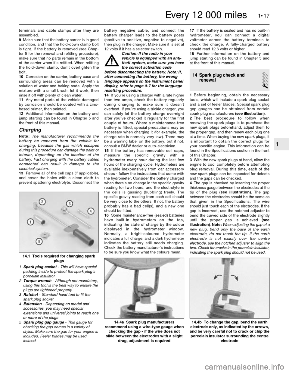
1Before beginning, obtain the necessary
tools, which will include a spark plug socket
and a set of feeler blades. Special spark plug
gap gauges can be obtained from certain
spark plug manufacturers (see illustration).
2The best procedure to follow when
renewing the spark plugs is to purchase the
new spark plugs beforehand, adjust them to
the proper gap, and then renew each plug one
at a time. When buying the new spark plugs, it
is important to obtain the correct plugs for
your specific engine. This information can be
found in the Specifications section in the front
of this Chapter.
3With the new spark plugs at hand, allow the
engine to cool completely before attempting
plug removal. During this time, each of the
new spark plugs can be inspected for defects
and the gaps can be checked.
4The gap is checked by inserting the proper
thickness gauge between the electrodes at the
tip of the plug (see illustration). The gap
between the electrodes should be the same as
that given in the Specifications. The wire
should just touch each of the electrodes. If the
gap is incorrect, use the notched adjuster to
bend the curved side of the electrode slightly
until the proper gap is achieved (see
illustration). Note: When adjusting the gap of a
new plug, bend only the base of the earth
electrode, do not touch the tip. If the earth
electrode is not exactly over the centre
electrode, use the notched adjuster to align the
two. Check for cracks in the porcelain insulator,
indicating the spark plug should not be used.
1•17
14.4b To change the gap, bend the earth
electrode only, as indicated by the arrows,
and be very careful not to crack or chip the
porcelain insulator surrounding the centre
electrode14.4a Spark plug manufacturers
recommend using a wire-type gauge when
checking the gap - if the wire does not
slide between the electrodes with a slight
drag, adjustment is required
14.1 Tools required for changing spark
plugs
1 Spark plug socket- This will have special
padding inside to protect the spark plug’s
porcelain insulator
2 Torque wrench - Although not mandatory,
using this tool is the best way to ensure the
plugs are tightened properly
3 Ratchet - Standard hand tool to fit the
spark plug socket
4 Extension - Depending on model and
accessories, you may need special
extensions and universal joints to reach one
or more of the plugs
5 Spark plug gap gauge- This gauge for
checking the gap comes in a variety of
styles. Make sure the gap for your engine is
included. Feeler blades may be used
instead
1
Every 12 000 miles
Page 29 of 228
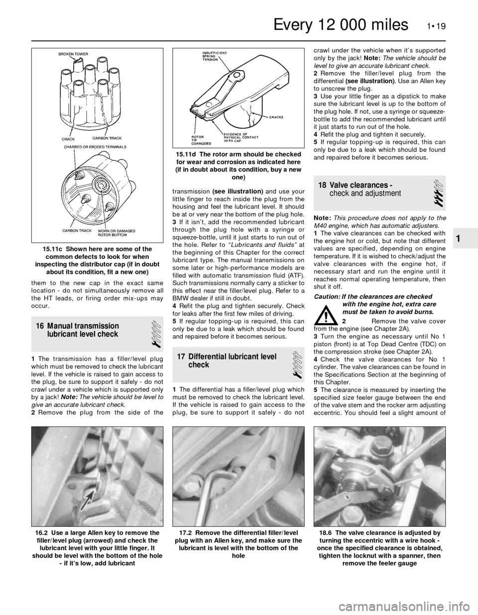
them to the new cap in the exact same
location - do not simultaneously remove all
the HT leads, or firing order mix-ups may
occur.
16 Manual transmission
lubricant level check
1
1The transmission has a filler/level plug
which must be removed to check the lubricant
level. If the vehicle is raised to gain access to
the plug, be sure to support it safely - do not
crawl under a vehicle which is supported only
by a jack!Note:The vehicle should be level to
give an accurate lubricant check.
2Remove the plug from the side of thetransmission (see illustration)and use your
little finger to reach inside the plug from the
housing and feel the lubricant level. It should
be at or very near the bottom of the plug hole.
3If it isn’t, add the recommended lubricant
through the plug hole with a syringe or
squeeze-bottle, until it just starts to run out of
the hole. Refer to “Lubricants and fluids” at
the beginning of this Chapter for the correct
lubricant type. The manual transmissions on
some later or high-performance models are
filled with automatic transmission fluid (ATF).
Such transmissions normally carry a sticker to
this effect near the filler/level plug. Refer to a
BMW dealer if still in doubt.
4Refit the plug and tighten securely. Check
for leaks after the first few miles of driving.
5If regular topping-up is required, this can
only be due to a leak which should be found
and repaired before it becomes serious.17 Differential lubricant level
check
1
1The differential has a filler/level plug which
must be removed to check the lubricant level.
If the vehicle is raised to gain access to the
plug, be sure to support it safely - do notcrawl under the vehicle when it’s supported
only by the jack! Note:The vehicle should be
level to give an accurate lubricant check.
2Remove the filler/level plug from the
differential (see illustration). Use an Allen key
to unscrew the plug.
3Use your little finger as a dipstick to make
sure the lubricant level is up to the bottom of
the plug hole. If not, use a syringe or squeeze-
bottle to add the recommended lubricant until
it just starts to run out of the hole.
4Refit the plug and tighten it securely.
5If regular topping-up is required, this can
only be due to a leak which should be found
and repaired before it becomes serious.
18 Valve clearances -
check and adjustment
3
Note:This procedure does not apply to the
M40 engine, which has automatic adjusters.
1The valve clearances can be checked with
the engine hot or cold, but note that different
values are specified, depending on engine
temperature. If it is wished to check/adjust the
valve clearances with the engine hot, if
necessary start and run the engine until it
reaches normal operating temperature, then
shut it off.
Caution: If the clearances are checked
with the engine hot, extra care
must be taken to avoid burns.
2Remove the valve cover
from the engine (see Chapter 2A).
3Turn the engine as necessary until No 1
piston (front) is at Top Dead Centre (TDC) on
the compression stroke (see Chapter 2A).
4Check the valve clearances for No 1
cylinder. The valve clearances can be found in
the Specifications Section at the beginning of
this Chapter.
5The clearance is measured by inserting the
specified size feeler gauge between the end
of the valve stem and the rocker arm adjusting
eccentric. You should feel a slight amount of
1•19
15.11d The rotor arm should be checked
for wear and corrosion as indicated here
(if in doubt about its condition, buy a new
one)
15.11c Shown here are some of the
common defects to look for when
inspecting the distributor cap (if in doubt
about its condition, fit a new one)
18.6 The valve clearance is adjusted by
turning the eccentric with a wire hook -
once the specified clearance is obtained,
tighten the locknut with a spanner, then
remove the feeler gauge17.2 Remove the differential filler/level
plug with an Allen key, and make sure the
lubricant is level with the bottom of the
hole16.2 Use a large Allen key to remove the
filler/level plug (arrowed) and check the
lubricant level with your little finger. It
should be level with the bottom of the hole
- if it’s low, add lubricant
1
Every 12 000 miles
Page 35 of 228
Flushing
7Once the system is completely drained,
flush the radiator with fresh water from a
garden hose until the water runs clear at the
drain or bottom hose. If the radiator is
severely corroded, damaged or leaking, it
should be removed (see Chapter 3) and taken
to a radiator repair specialist.
8Flushing in this way will remove sediments
from the radiator, but will not remove rust and
scale from the engine and cooling tube
surfaces. These deposits can be removed by
using a chemical cleaner. Follow the
procedure outlined in the cleaner
manufacturer’s instructions. Remove the
cylinder block drain plug before flushing the
engine.
9On models so equipped, remove the
overflow hose from the coolant recovery
reservoir. Drain the reservoir and flush it with
clean water, then reconnect the hose.
Refilling
10Tighten the radiator drain plug, or
reconnect the radiator bottom hose. Refit and
tighten the cylinder block drain plug.
Four-cylinder engines
11Slowly add new coolant (a 40%/60%
mixture of antifreeze to water) to the radiator
until it is full. Add coolant to the reservoir up
to the lower mark.
12Leave the radiator cap off, and run the
engine in a well-ventilated area until the
thermostat opens (coolant will begin flowing
through the radiator, and the upper radiator
hose will become hot).
13Turn the engine off, and let it cool. Add
more coolant mixture to bring the coolant
level back up to the lip on the radiator filler
neck. On the M40 engine, unscrew the bleed
screw from the top of the radiator, and add
coolant until it comes out of the bleed screw
hole. Refit and tighten the bleed screw.
14Squeeze the upper radiator hose to expel
air, then add more coolant mixture if
necessary. Refit the radiator cap.
15Start the engine, allow it to reach normal
operating temperature, and check for leaks.
Six-cylinder engines
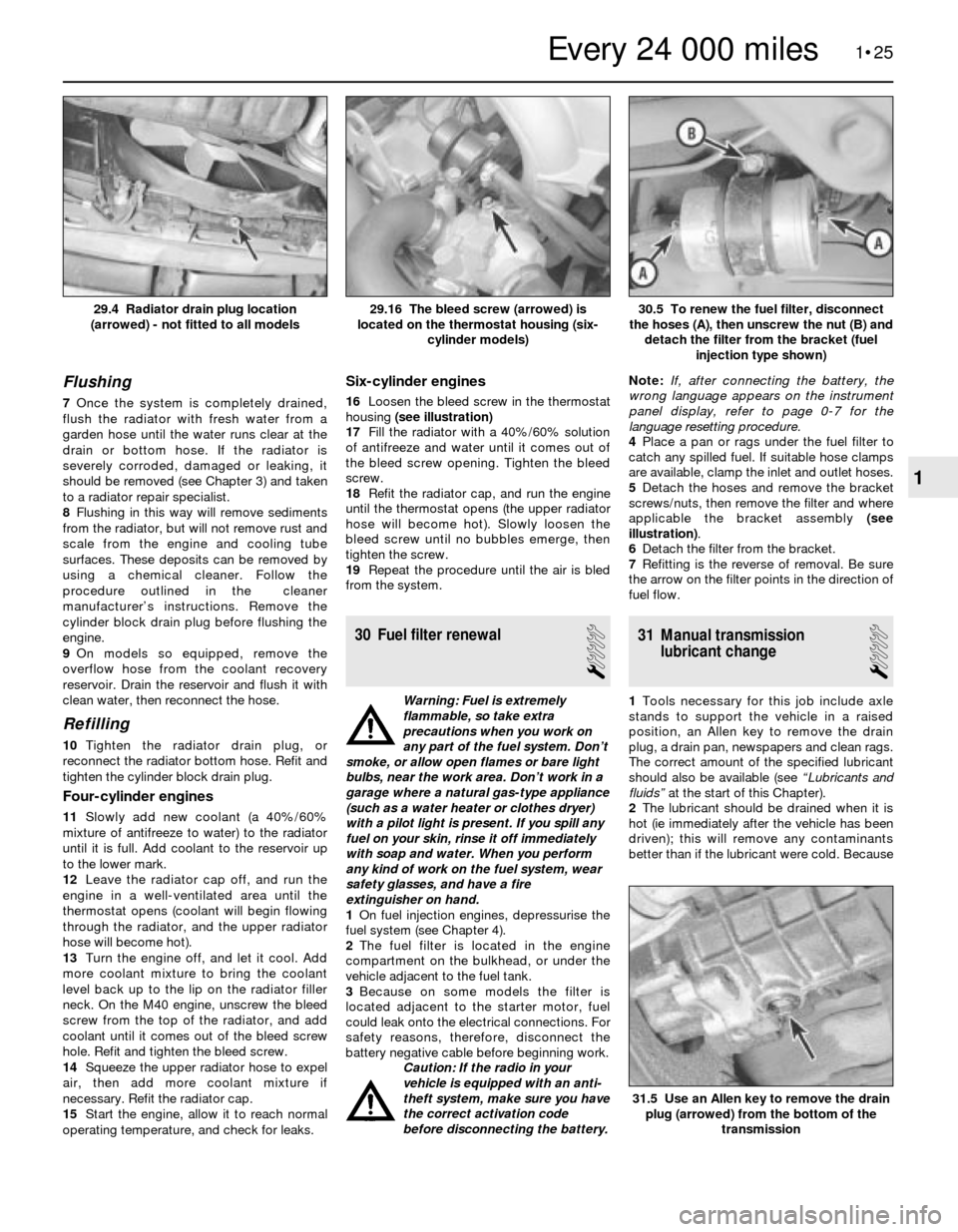
16Loosen the bleed screw in the thermostat
housing (see illustration)
17Fill the radiator with a 40%/60% solution
of antifreeze and water until it comes out of
the bleed screw opening. Tighten the bleed
screw.
18Refit the radiator cap, and run the engine
until the thermostat opens (the upper radiator
hose will become hot). Slowly loosen the
bleed screw until no bubbles emerge, then
tighten the screw.
19Repeat the procedure until the air is bled
from the system.
30 Fuel filter renewal
1
Warning: Fuel is extremely
flammable, so take extra
precautions when you work on
any part of the fuel system. Don’t
smoke, or allow open flames or bare light
bulbs, near the work area. Don’t work in a
garage where a natural gas-type appliance
(such as a water heater or clothes dryer)
with a pilot light is present. If you spill any
fuel on your skin, rinse it off immediately
with soap and water. When you perform
any kind of work on the fuel system, wear
safety glasses, and have a fire
extinguisher on hand.
1On fuel injection engines, depressurise the
fuel system (see Chapter 4).
2The fuel filter is located in the engine
compartment on the bulkhead, or under the
vehicle adjacent to the fuel tank.
3Because on some models the filter is
located adjacent to the starter motor, fuel
could leak onto the electrical connections. For
safety reasons, therefore, disconnect the
battery negative cable before beginning work.
Caution: If the radio in your
vehicle is equipped with an anti-
theft system, make sure you have
the correct activation code
before disconnecting the battery.Note: If, after connecting the battery, the
wrong language appears on the instrument
panel display, refer to page 0-7 for the
language resetting procedure.
4Place a pan or rags under the fuel filter to
catch any spilled fuel. If suitable hose clamps
are available, clamp the inlet and outlet hoses.
5 Detach the hoses and remove the bracket
screws/nuts, then remove the filter and where
applicable the bracket assembly (see
illustration).
6Detach the filter from the bracket.
7Refitting is the reverse of removal. Be sure
the arrow on the filter points in the direction of
fuel flow.
31 Manual transmission
lubricant change
1
1Tools necessary for this job include axle
stands to support the vehicle in a raised
position, an Allen key to remove the drain
plug, a drain pan, newspapers and clean rags.
The correct amount of the specified lubricant
should also be available (see “Lubricants and
fluids”at the start of this Chapter).
2The lubricant should be drained when it is
hot (ie immediately after the vehicle has been
driven); this will remove any contaminants
better than if the lubricant were cold. Because
1•25
30.5 To renew the fuel filter, disconnect
the hoses (A), then unscrew the nut (B) and
detach the filter from the bracket (fuel
injection type shown)29.16 The bleed screw (arrowed) is
located on the thermostat housing (six-
cylinder models)29.4 Radiator drain plug location
(arrowed) - not fitted to all models
31.5 Use an Allen key to remove the drain
plug (arrowed) from the bottom of the
transmission
1
Every 24 000 miles
Page 36 of 228
the lubricant will be hot, it would be wise to
wear rubber gloves.
3Raise the vehicle and place it on axle
stands. Make sure it is safely supported, and
as level as possible.
4Move the necessary equipment under the
vehicle, being careful not to touch any of the
hot exhaust components.
5Place the drain pan under the transmission,
and remove the filler/level plug from the side
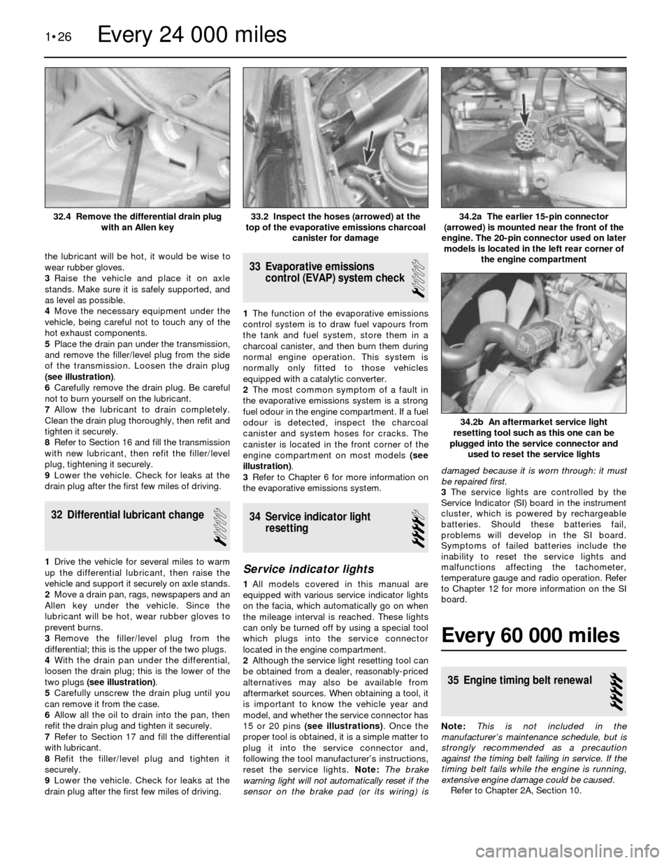
of the transmission. Loosen the drain plug
(see illustration).
6Carefully remove the drain plug. Be careful
not to burn yourself on the lubricant.
7Allow the lubricant to drain completely.
Clean the drain plug thoroughly, then refit and
tighten it securely.
8Refer to Section 16 and fill the transmission
with new lubricant, then refit the filler/level
plug, tightening it securely.
9Lower the vehicle. Check for leaks at the
drain plug after the first few miles of driving.
32 Differential lubricant change
1
1Drive the vehicle for several miles to warm
up the differential lubricant, then raise the
vehicle and support it securely on axle stands.
2Move a drain pan, rags, newspapers and an
Allen key under the vehicle. Since the
lubricant will be hot, wear rubber gloves to
prevent burns.
3Remove the filler/level plug from the
differential; this is the upper of the two plugs.
4With the drain pan under the differential,
loosen the drain plug; this is the lower of the
two plugs (see illustration).
5Carefully unscrew the drain plug until you
can remove it from the case.
6Allow all the oil to drain into the pan, then
refit the drain plug and tighten it securely.
7Refer to Section 17 and fill the differential
with lubricant.
8Refit the filler/level plug and tighten it
securely.
9Lower the vehicle. Check for leaks at the
drain plug after the first few miles of driving.
33 Evaporative emissions
control (EVAP) system check
1
1The function of the evaporative emissions
control system is to draw fuel vapours from
the tank and fuel system, store them in a
charcoal canister, and then burn them during
normal engine operation. This system is
normally only fitted to those vehicles
equipped with a catalytic converter.
2The most common symptom of a fault in
the evaporative emissions system is a strong
fuel odour in the engine compartment. If a fuel
odour is detected, inspect the charcoal
canister and system hoses for cracks. The
canister is located in the front corner of the
engine compartment on most models (see
illustration).
3Refer to Chapter 6 for more information on
the evaporative emissions system.
34 Service indicator light
resetting
4
Service indicator lights
1All models covered in this manual are
equipped with various service indicator lights
on the facia, which automatically go on when
the mileage interval is reached. These lights
can only be turned off by using a special tool
which plugs into the service connector
located in the engine compartment.
2Although the service light resetting tool can
be obtained from a dealer, reasonably-priced
alternatives may also be available from
aftermarket sources. When obtaining a tool, it
is important to know the vehicle year and
model, and whether the service connector has
15 or 20 pins (see illustrations). Once the
proper tool is obtained, it is a simple matter to
plug it into the service connector and,
following the tool manufacturer’s instructions,
reset the service lights. Note: The brake
warning light will not automatically reset if the
sensor on the brake pad (or its wiring) isdamaged because it is worn through: it must
be repaired first.
3The service lights are controlled by the
Service Indicator (SI) board in the instrument
cluster, which is powered by rechargeable
batteries. Should these batteries fail,
problems will develop in the SI board.
Symptoms of failed batteries include the
inability to reset the service lights and
malfunctions affecting the tachometer,
temperature gauge and radio operation. Refer
to Chapter 12 for more information on the SI
board.
Every 60 000 miles
35 Engine timing belt renewal
5
Note:This is not included in the
manufacturer’s maintenance schedule, but is
strongly recommended as a precaution
against the timing belt failing in service. If the
timing belt fails while the engine is running,
extensive engine damage could be caused.
Refer to Chapter 2A, Section 10.
1•26
34.2b An aftermarket service light
resetting tool such as this one can be
plugged into the service connector and
used to reset the service lights
34.2a The earlier 15-pin connector
(arrowed) is mounted near the front of the
engine. The 20-pin connector used on later
models is located in the left rear corner of
the engine compartment33.2 Inspect the hoses (arrowed) at the
top of the evaporative emissions charcoal
canister for damage32.4 Remove the differential drain plug
with an Allen key
Every 24 000 miles
Page 38 of 228
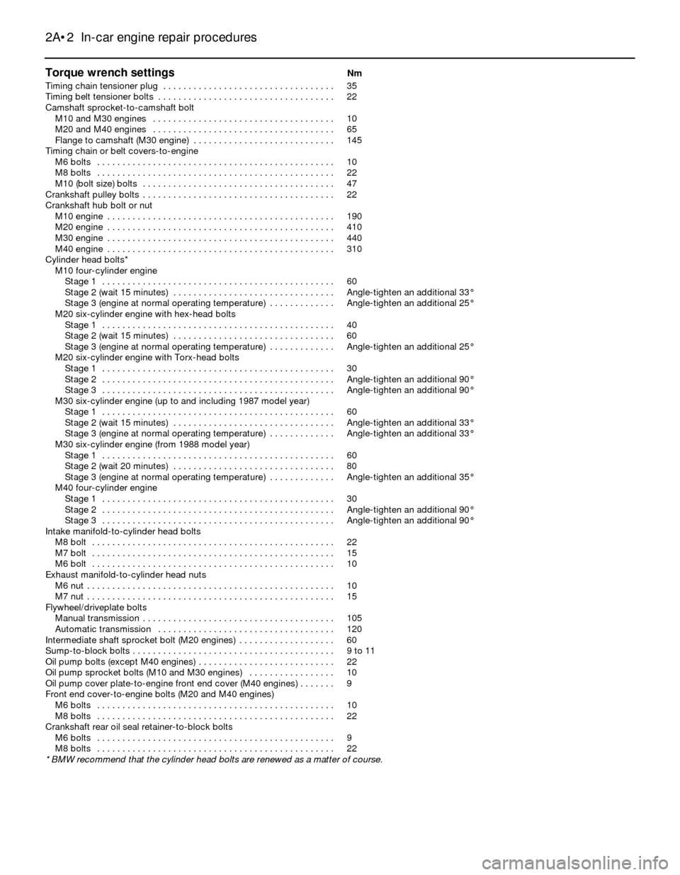
Torque wrench settingsNm
Timing chain tensioner plug . . . . . . . . . . . . . . . . . . . . . . . . . . . . . . . . . . 35
Timing belt tensioner bolts . . . . . . . . . . . . . . . . . . . . . . . . . . . . . . . . . . . 22
Camshaft sprocket-to-camshaft bolt
M10 and M30 engines . . . . . . . . . . . . . . . . . . . . . . . . . . . . . . . . . . . . 10
M20 and M40 engines . . . . . . . . . . . . . . . . . . . . . . . . . . . . . . . . . . . . 65
Flange to camshaft (M30 engine) . . . . . . . . . . . . . . . . . . . . . . . . . . . . 145
Timing chain or belt covers-to-engine
M6 bolts . . . . . . . . . . . . . . . . . . . . . . . . . . . . . . . . . . . . . . . . . . . . . . . 10
M8 bolts . . . . . . . . . . . . . . . . . . . . . . . . . . . . . . . . . . . . . . . . . . . . . . . 22
M10 (bolt size) bolts . . . . . . . . . . . . . . . . . . . . . . . . . . . . . . . . . . . . . . 47
Crankshaft pulley bolts . . . . . . . . . . . . . . . . . . . . . . . . . . . . . . . . . . . . . . 22
Crankshaft hub bolt or nut
M10 engine . . . . . . . . . . . . . . . . . . . . . . . . . . . . . . . . . . . . . . . . . . . . . 190
M20 engine . . . . . . . . . . . . . . . . . . . . . . . . . . . . . . . . . . . . . . . . . . . . . 410
M30 engine . . . . . . . . . . . . . . . . . . . . . . . . . . . . . . . . . . . . . . . . . . . . . 440
M40 engine . . . . . . . . . . . . . . . . . . . . . . . . . . . . . . . . . . . . . . . . . . . . . 310
Cylinder head bolts*
M10 four-cylinder engine
Stage 1 . . . . . . . . . . . . . . . . . . . . . . . . . . . . . . . . . . . . . . . . . . . . . . 60
Stage 2 (wait 15 minutes) . . . . . . . . . . . . . . . . . . . . . . . . . . . . . . . . Angle-tighten an additional 33°
Stage 3 (engine at normal operating temperature) . . . . . . . . . . . . . Angle-tighten an additional 25°
M20 six-cylinder engine with hex-head bolts
Stage 1 . . . . . . . . . . . . . . . . . . . . . . . . . . . . . . . . . . . . . . . . . . . . . . 40
Stage 2 (wait 15 minutes) . . . . . . . . . . . . . . . . . . . . . . . . . . . . . . . . 60
Stage 3 (engine at normal operating temperature) . . . . . . . . . . . . . Angle-tighten an additional 25°
M20 six-cylinder engine with Torx-head bolts
Stage 1 . . . . . . . . . . . . . . . . . . . . . . . . . . . . . . . . . . . . . . . . . . . . . . 30
Stage 2 . . . . . . . . . . . . . . . . . . . . . . . . . . . . . . . . . . . . . . . . . . . . . . Angle-tighten an additional 90°
Stage 3 . . . . . . . . . . . . . . . . . . . . . . . . . . . . . . . . . . . . . . . . . . . . . . Angle-tighten an additional 90°
M30 six-cylinder engine (up to and including 1987 model year)
Stage 1 . . . . . . . . . . . . . . . . . . . . . . . . . . . . . . . . . . . . . . . . . . . . . . 60
Stage 2 (wait 15 minutes) . . . . . . . . . . . . . . . . . . . . . . . . . . . . . . . . Angle-tighten an additional 33°
Stage 3 (engine at normal operating temperature) . . . . . . . . . . . . . Angle-tighten an additional 33°
M30 six-cylinder engine (from 1988 model year)
Stage 1 . . . . . . . . . . . . . . . . . . . . . . . . . . . . . . . . . . . . . . . . . . . . . . 60
Stage 2 (wait 20 minutes) . . . . . . . . . . . . . . . . . . . . . . . . . . . . . . . . 80
Stage 3 (engine at normal operating temperature) . . . . . . . . . . . . . Angle-tighten an additional 35°
M40 four-cylinder engine
Stage 1 . . . . . . . . . . . . . . . . . . . . . . . . . . . . . . . . . . . . . . . . . . . . . . 30
Stage 2 . . . . . . . . . . . . . . . . . . . . . . . . . . . . . . . . . . . . . . . . . . . . . . Angle-tighten an additional 90°
Stage 3 . . . . . . . . . . . . . . . . . . . . . . . . . . . . . . . . . . . . . . . . . . . . . . Angle-tighten an additional 90°
Intake manifold-to-cylinder head bolts
M8 bolt . . . . . . . . . . . . . . . . . . . . . . . . . . . . . . . . . . . . . . . . . . . . . . . . 22
M7 bolt . . . . . . . . . . . . . . . . . . . . . . . . . . . . . . . . . . . . . . . . . . . . . . . . 15
M6 bolt . . . . . . . . . . . . . . . . . . . . . . . . . . . . . . . . . . . . . . . . . . . . . . . . 10
Exhaust manifold-to-cylinder head nuts
M6 nut . . . . . . . . . . . . . . . . . . . . . . . . . . . . . . . . . . . . . . . . . . . . . . . . . 10
M7 nut . . . . . . . . . . . . . . . . . . . . . . . . . . . . . . . . . . . . . . . . . . . . . . . . . 15
Flywheel/driveplate bolts
Manual transmission . . . . . . . . . . . . . . . . . . . . . . . . . . . . . . . . . . . . . . 105
Automatic transmission . . . . . . . . . . . . . . . . . . . . . . . . . . . . . . . . . . . 120
Intermediate shaft sprocket bolt (M20 engines) . . . . . . . . . . . . . . . . . . . 60
Sump-to-block bolts . . . . . . . . . . . . . . . . . . . . . . . . . . . . . . . . . . . . . . . . 9 to 11
Oil pump bolts (except M40 engines) . . . . . . . . . . . . . . . . . . . . . . . . . . . 22
Oil pump sprocket bolts (M10 and M30 engines) . . . . . . . . . . . . . . . . . 10
Oil pump cover plate-to-engine front end cover (M40 engines) . . . . . . . 9
Front end cover-to-engine bolts (M20 and M40 engines)
M6 bolts . . . . . . . . . . . . . . . . . . . . . . . . . . . . . . . . . . . . . . . . . . . . . . . 10
M8 bolts . . . . . . . . . . . . . . . . . . . . . . . . . . . . . . . . . . . . . . . . . . . . . . . 22
Crankshaft rear oil seal retainer-to-block bolts
M6 bolts . . . . . . . . . . . . . . . . . . . . . . . . . . . . . . . . . . . . . . . . . . . . . . . 9
M8 bolts . . . . . . . . . . . . . . . . . . . . . . . . . . . . . . . . . . . . . . . . . . . . . . . 22
* BMW recommend that the cylinder head bolts are renewed as a matter of course.
2A•2 In-car engine repair procedures
Page 39 of 228
1 General information
This Part of Chapter 2 is devoted to in-
vehicle engine repair procedures. All
information concerning engine removal and
refitting and engine block and cylinder head
overhaul can be found in Chapter 2B.
The following repair procedures are based
on the assumption that the engine is still fitted
in the vehicle. If the engine has been removed
from the vehicle and mounted on a stand,
many of the steps outlined in this Part of
Chapter 2 will not apply.
The Specifications included in this Part of
Chapter 2 apply only to the procedures
contained in this Part. Chapter 2B contains
the Specifications necessary for cylinder head
and engine block rebuilding.
The single overhead camshaft four- and
six-cylinder engines covered in this manual
are very similar in design. Where there are
differences, they will be pointed out.
The means by which the overhead
camshaft is driven varies according to engine
type; M10 and M30 engines use a timing
chain, while M20 and M40 engines have a
timing belt.
2 Repair operations possible
with the engine in the vehicle
Many major repair operations can be
accomplished without removing the engine
from the vehicle.
Clean the engine compartment and the
exterior of the engine with some type of
degreaser before any work is done. It will
make the job easier, and help keep dirt out of
the internal areas of the engine.
Depending on the components involved, it
may be helpful to remove the bonnet to
improve access to the engine as repairs are
performed (see Chapter 11 if necessary).
Cover the wings to prevent damage to the
paint. Special pads are available, but an old
bedspread or blanket will also work.
If vacuum, exhaust, oil or coolant leaks
develop, indicating a need for gasket or seal
renewal, the repairs can generally be made
with the engine in the vehicle. The intake and
exhaust manifold gaskets, sump gasket,
crankshaft oil seals and cylinder head gasket
are all accessible with the engine in place.
Exterior components, such as the intake
and exhaust manifolds, the sump, the oil
pump, the water pump, the starter motor, the
alternator, the distributor and the fuel system
components, can be removed for repair with
the engine in place.
The cylinder head can be removed without
removing the engine, so this procedure is
covered in this Part of Chapter 2. Camshaft,
rocker arm and valve component servicing ismost easily accomplished with the cylinder
head removed; these procedures are covered
in Part B of this Chapter. Note, however, that
the camshaft on the M40 engine may be
removed with the engine in the vehicle since it
is retained by bearing caps.
In extreme cases caused by a lack of
necessary equipment, repair or renewal of
piston rings, pistons, connecting rods and
big-end bearings is possible with the engine in
the vehicle. However, this practice is not
recommended, because of the cleaning and
preparation work that must be done to the
components involved.
3 Top Dead Centre (TDC) for
No 1 piston- locating
2
Note 1:The following procedure is based on
the assumption that the distributor (if
applicable) is correctly fitted. If you are trying
to locate TDC to refit the distributor correctly,
piston position must be determined by feeling
for compression at the No 1 spark plug hole,
then aligning the ignition timing marks or
inserting the timing tool in the flywheel, as
applicable.
Note 2:The No 1 cylinder is the one closest to
the radiator.
1Top Dead Centre (TDC) is the highest point
in the cylinder that each piston reaches as it
travels up and down when the crankshaft
turns. Each piston reaches TDC on the
compression stroke and again on the exhaust
stroke, but TDC generally refers to piston
position on the compression stroke.
2Positioning the piston at TDC is an essential
part of many procedures, such as timing belt
or chain removal and distributor removal.
3Before beginning this procedure, be sure to
place the transmission in Neutral, and apply
the handbrake or chock the rear wheels. Also,
disable the ignition system by detaching the
coil wire from the centre terminal of the
distributor cap, and earthing it on the engine
block with a jumper wire. Remove the spark
plugs (see Chapter 1).
4In order to bring any piston to TDC, the
crankshaft must be turned using one of the
methods outlined below. When looking at the
front of the engine, normal crankshaft rotation
is clockwise.
(a) The preferred method is to turn the
crankshaft with a socket and ratchet
attached to the bolt threaded into the
front of the crankshaft.
(b) A remote starter switch, which may save
some time, can also be used. Follow the
instructions included with the switch.
Once the piston is close to TDC, use a
socket and ratchet as described in the
previous paragraph.
(c) If an assistant is available to turn the
ignition switch to the Start position in
short bursts, you can get the piston close
to TDC without a remote starter switch.Make sure your assistant is out of the
vehicle, away from the ignition switch,
then use a socket and ratchet as
described in (a) to complete the
procedure.
5Note the position of the terminal for the
No 1 spark plug lead on the distributor cap. If
the terminal isn’t marked, follow the plug lead
from the No 1 cylinder spark plug to the cap
(No 1 cylinder is nearest the radiator).
6Use a felt-tip pen or chalk to make a mark
directly below the No 1 terminal on the
distributor body or timing cover.
7Detach the distributor cap, and set it aside
(see Chapter 1 if necessary).
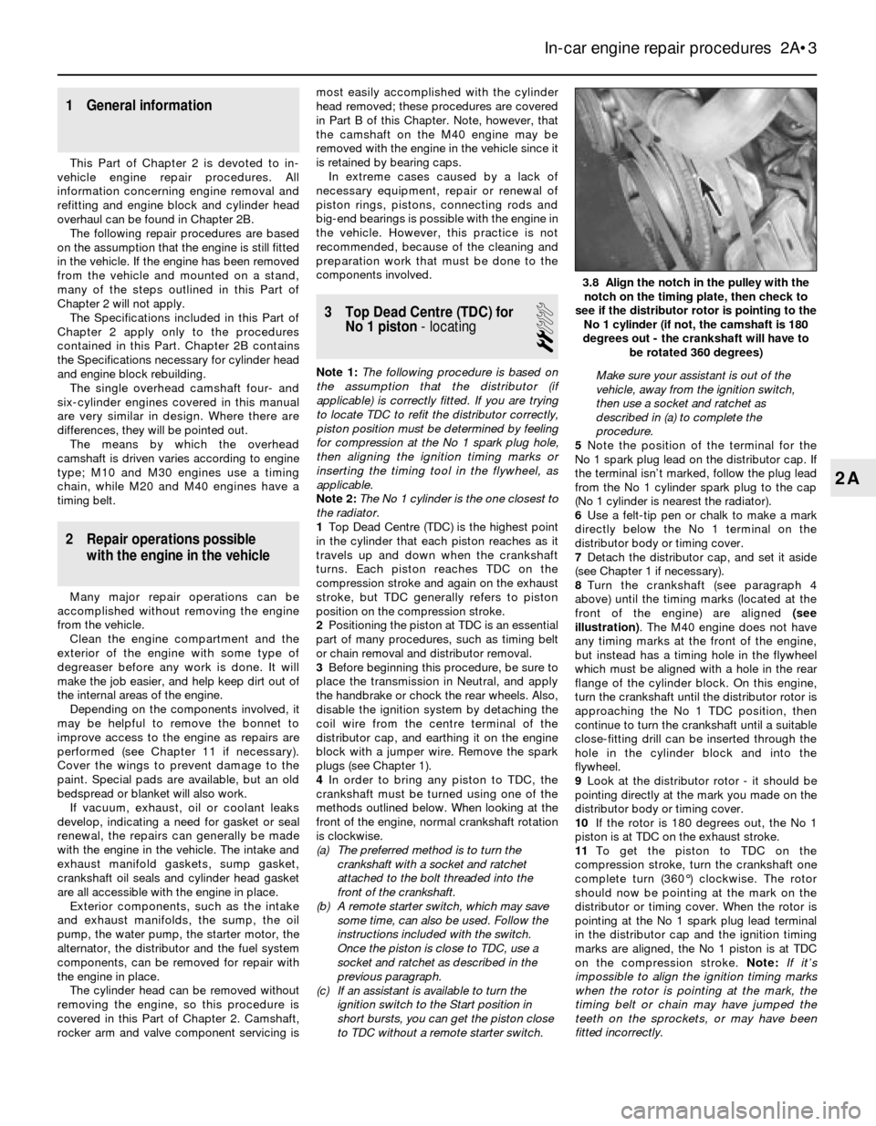
8Turn the crankshaft (see paragraph 4
above) until the timing marks (located at the
front of the engine) are aligned (see
illustration). The M40 engine does not have
any timing marks at the front of the engine,
but instead has a timing hole in the flywheel
which must be aligned with a hole in the rear
flange of the cylinder block. On this engine,
turn the crankshaft until the distributor rotor is
approaching the No 1 TDC position, then
continue to turn the crankshaft until a suitable
close-fitting drill can be inserted through the
hole in the cylinder block and into the
flywheel.
9Look at the distributor rotor - it should be
pointing directly at the mark you made on the
distributor body or timing cover.
10If the rotor is 180 degrees out, the No 1
piston is at TDC on the exhaust stroke.
11To get the piston to TDC on the
compression stroke, turn the crankshaft one
complete turn (360°) clockwise. The rotor
should now be pointing at the mark on the
distributor or timing cover. When the rotor is
pointing at the No 1 spark plug lead terminal
in the distributor cap and the ignition timing
marks are aligned, the No 1 piston is at TDC
on the compression stroke. Note:If it’s
impossible to align the ignition timing marks
when the rotor is pointing at the mark, the
timing belt or chain may have jumped the
teeth on the sprockets, or may have been
fitted incorrectly.
In-car engine repair procedures 2A•3
3.8 Align the notch in the pulley with the
notch on the timing plate, then check to
see if the distributor rotor is pointing to the
No 1 cylinder (if not, the camshaft is 180
degrees out - the crankshaft will have to
be rotated 360 degrees)
2A
Page 54 of 228
26Refit the cover plate and tighten the bolts
to the specified torque.
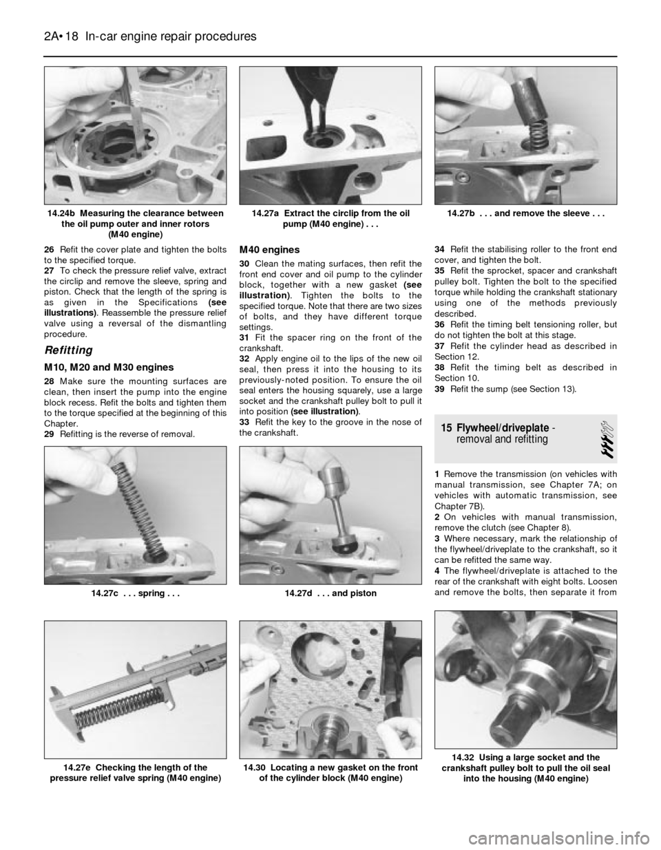
27To check the pressure relief valve, extract
the circlip and remove the sleeve, spring and
piston. Check that the length of the spring is
as given in the Specifications (see
illustrations). Reassemble the pressure relief
valve using a reversal of the dismantling
procedure.
Refitting
M10, M20 and M30 engines
28Make sure the mounting surfaces are
clean, then insert the pump into the engine
block recess. Refit the bolts and tighten them
to the torque specified at the beginning of this
Chapter.
29Refitting is the reverse of removal.
M40 engines
30Clean the mating surfaces, then refit the
front end cover and oil pump to the cylinder
block, together with a new gasket (see
illustration). Tighten the bolts to the
specified torque. Note that there are two sizes
of bolts, and they have different torque
settings.
31Fit the spacer ring on the front of the
crankshaft.
32Apply engine oil to the lips of the new oil
seal, then press it into the housing to its
previously-noted position. To ensure the oil
seal enters the housing squarely, use a large
socket and the crankshaft pulley bolt to pull it
into position (see illustration).
33Refit the key to the groove in the nose of
the crankshaft.34Refit the stabilising roller to the front end
cover, and tighten the bolt.
35Refit the sprocket, spacer and crankshaft
pulley bolt. Tighten the bolt to the specified
torque while holding the crankshaft stationary
using one of the methods previously
described.
36Refit the timing belt tensioning roller, but
do not tighten the bolt at this stage.
37Refit the cylinder head as described in
Section 12.
38Refit the timing belt as described in
Section 10.
39Refit the sump (see Section 13).
15 Flywheel/driveplate-
removal and refitting
3
1Remove the transmission (on vehicles with
manual transmission, see Chapter 7A; on
vehicles with automatic transmission, see
Chapter 7B).
2On vehicles with manual transmission,
remove the clutch (see Chapter 8).
3Where necessary, mark the relationship of
the flywheel/driveplate to the crankshaft, so it
can be refitted the same way.
4The flywheel/driveplate is attached to the
rear of the crankshaft with eight bolts. Loosen
and remove the bolts, then separate it from
2A•18 In-car engine repair procedures
14.32 Using a large socket and the
crankshaft pulley bolt to pull the oil seal
into the housing (M40 engine)14.30 Locating a new gasket on the front
of the cylinder block (M40 engine)14.27e Checking the length of the
pressure relief valve spring (M40 engine)
14.27d . . . and piston14.27c . . . spring . . .
14.27b . . . and remove the sleeve . . .14.27a Extract the circlip from the oil
pump (M40 engine) . . .14.24b Measuring the clearance between
the oil pump outer and inner rotors
(M40 engine)