head bolt sequence BMW 3 SERIES 1988 E30 Workshop Manual
[x] Cancel search | Manufacturer: BMW, Model Year: 1988, Model line: 3 SERIES, Model: BMW 3 SERIES 1988 E30Pages: 228, PDF Size: 7.04 MB
Page 49 of 228
22Using a scraper, remove all traces of old
gasket material from the sealing surfaces of
the covers and engine block.
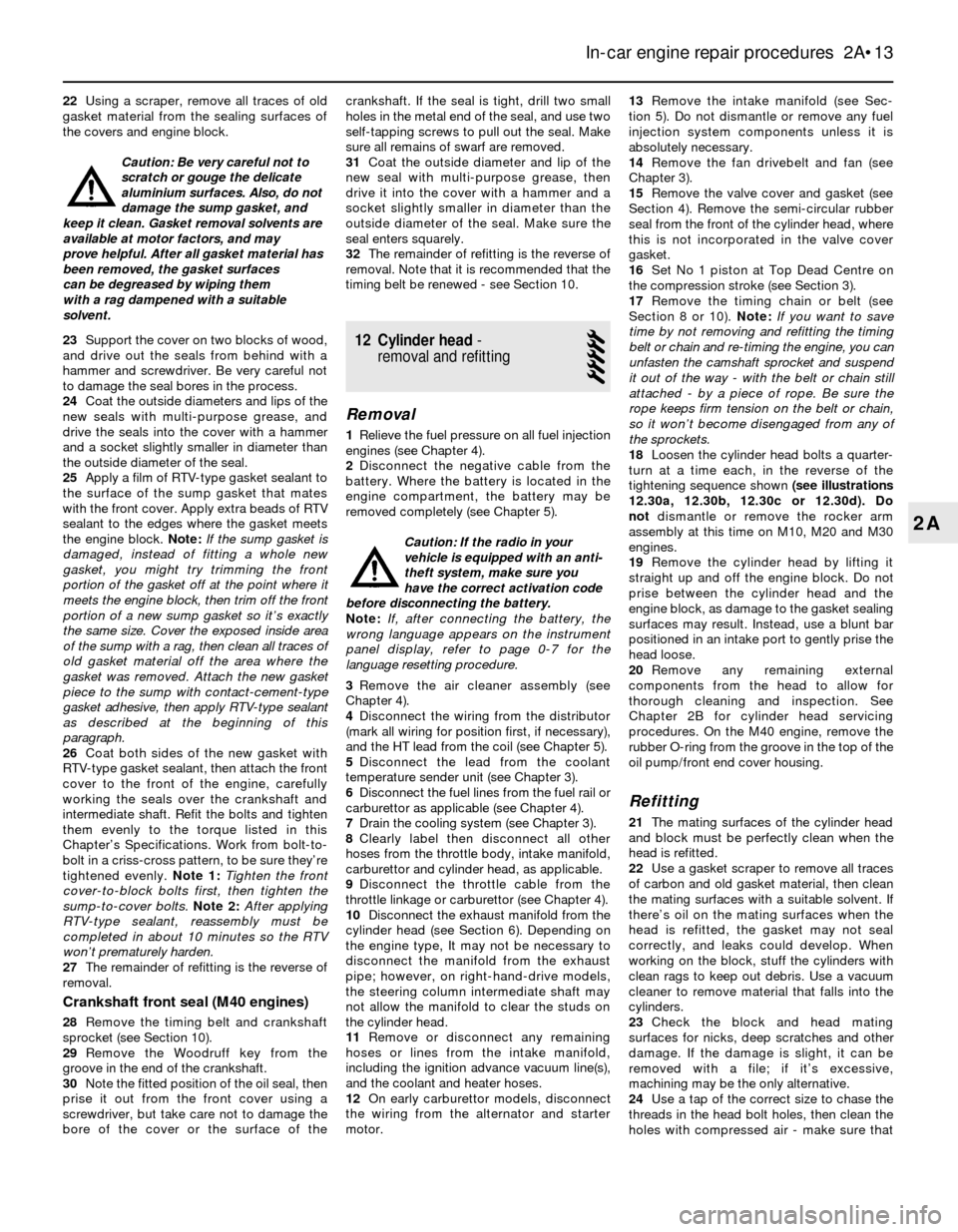
Caution: Be very careful not to
scratch or gouge the delicate
aluminium surfaces. Also, do not
damage the sump gasket, and
keep it clean. Gasket removal solvents are
available at motor factors, and may
prove helpful. After all gasket material has
been removed, the gasket surfaces
can be degreased by wiping them
with a rag dampened with a suitable
solvent.
23Support the cover on two blocks of wood,
and drive out the seals from behind with a
hammer and screwdriver. Be very careful not
to damage the seal bores in the process.
24Coat the outside diameters and lips of the
new seals with multi-purpose grease, and
drive the seals into the cover with a hammer
and a socket slightly smaller in diameter than
the outside diameter of the seal.
25Apply a film of RTV-type gasket sealant to
the surface of the sump gasket that mates
with the front cover. Apply extra beads of RTV
sealant to the edges where the gasket meets
the engine block. Note:If the sump gasket is
damaged, instead of fitting a whole new
gasket, you might try trimming the front
portion of the gasket off at the point where it
meets the engine block, then trim off the front
portion of a new sump gasket so it’s exactly
the same size. Cover the exposed inside area
of the sump with a rag, then clean all traces of
old gasket material off the area where the
gasket was removed. Attach the new gasket
piece to the sump with contact-cement-type
gasket adhesive, then apply RTV-type sealant
as described at the beginning of this
paragraph.
26Coat both sides of the new gasket with
RTV-type gasket sealant, then attach the front
cover to the front of the engine, carefully
working the seals over the crankshaft and
intermediate shaft. Refit the bolts and tighten
them evenly to the torque listed in this
Chapter’s Specifications. Work from bolt-to-
bolt in a criss-cross pattern, to be sure they’re
tightened evenly.Note 1:Tighten the front
cover-to-block bolts first, then tighten the
sump-to-cover bolts. Note 2:After applying
RTV-type sealant, reassembly must be
completed in about 10 minutes so the RTV
won’t prematurely harden.
27The remainder of refitting is the reverse of
removal.
Crankshaft front seal (M40 engines)
28Remove the timing belt and crankshaft
sprocket (see Section 10).
29Remove the Woodruff key from the
groove in the end of the crankshaft.
30Note the fitted position of the oil seal, then
prise it out from the front cover using a
screwdriver, but take care not to damage the
bore of the cover or the surface of thecrankshaft. If the seal is tight, drill two small
holes in the metal end of the seal, and use two
self-tapping screws to pull out the seal. Make
sure all remains of swarf are removed.
31Coat the outside diameter and lip of the
new seal with multi-purpose grease, then
drive it into the cover with a hammer and a
socket slightly smaller in diameter than the
outside diameter of the seal. Make sure the
seal enters squarely.
32The remainder of refitting is the reverse of
removal. Note that it is recommended that the
timing belt be renewed - see Section 10.
12 Cylinder head-
removal and refitting
5
Removal
1Relieve the fuel pressure on all fuel injection
engines (see Chapter 4).
2Disconnect the negative cable from the
battery. Where the battery is located in the
engine compartment, the battery may be
removed completely (see Chapter 5).
Caution: If the radio in your
vehicle is equipped with an anti-
theft system, make sure you
have the correct activation code
before disconnecting the battery.
Note: If, after connecting the battery, the
wrong language appears on the instrument
panel display, refer to page 0-7 for the
language resetting procedure.
3Remove the air cleaner assembly (see
Chapter 4).
4Disconnect the wiring from the distributor
(mark all wiring for position first, if necessary),
and the HT lead from the coil (see Chapter 5).
5Disconnect the lead from the coolant
temperature sender unit (see Chapter 3).
6Disconnect the fuel lines from the fuel rail or
carburettor as applicable (see Chapter 4).
7Drain the cooling system (see Chapter 3).
8Clearly label then disconnect all other
hoses from the throttle body, intake manifold,
carburettor and cylinder head, as applicable.
9Disconnect the throttle cable from the
throttle linkage or carburettor (see Chapter 4).
10Disconnect the exhaust manifold from the
cylinder head (see Section 6). Depending on
the engine type, It may not be necessary to
disconnect the manifold from the exhaust
pipe; however, on right-hand-drive models,
the steering column intermediate shaft may
not allow the manifold to clear the studs on
the cylinder head.
11Remove or disconnect any remaining
hoses or lines from the intake manifold,
including the ignition advance vacuum line(s),
and the coolant and heater hoses.
12On early carburettor models, disconnect
the wiring from the alternator and starter
motor.13Remove the intake manifold (see Sec-
tion 5). Do not dismantle or remove any fuel
injection system components unless it is
absolutely necessary.
14Remove the fan drivebelt and fan (see
Chapter 3).
15Remove the valve cover and gasket (see
Section 4). Remove the semi-circular rubber
seal from the front of the cylinder head, where
this is not incorporated in the valve cover
gasket.
16Set No 1 piston at Top Dead Centre on
the compression stroke (see Section 3).
17Remove the timing chain or belt (see
Section 8 or 10). Note:If you want to save
time by not removing and refitting the timing
belt or chain and re-timing the engine, you can
unfasten the camshaft sprocket and suspend
it out of the way - with the belt or chain still
attached - by a piece of rope. Be sure the
rope keeps firm tension on the belt or chain,
so it won’t become disengaged from any of
the sprockets.
18Loosen the cylinder head bolts a quarter-
turn at a time each, in the reverse of the
tightening sequence shown (see illustrations
12.30a, 12.30b, 12.30c or 12.30d). Do
notdismantle or remove the rocker arm
assembly at this time on M10, M20 and M30
engines.
19Remove the cylinder head by lifting it
straight up and off the engine block. Do not
prise between the cylinder head and the
engine block, as damage to the gasket sealing
surfaces may result. Instead, use a blunt bar
positioned in an intake port to gently prise the
head loose.
20Remove any remaining external
components from the head to allow for
thorough cleaning and inspection. See
Chapter 2B for cylinder head servicing
procedures. On the M40 engine, remove the
rubber O-ring from the groove in the top of the
oil pump/front end cover housing.
Refitting
21The mating surfaces of the cylinder head
and block must be perfectly clean when the
head is refitted.
22Use a gasket scraper to remove all traces
of carbon and old gasket material, then clean
the mating surfaces with a suitable solvent. If
there’s oil on the mating surfaces when the
head is refitted, the gasket may not seal
correctly, and leaks could develop. When
working on the block, stuff the cylinders with
clean rags to keep out debris. Use a vacuum
cleaner to remove material that falls into the
cylinders.
23Check the block and head mating
surfaces for nicks, deep scratches and other
damage. If the damage is slight, it can be
removed with a file; if it’s excessive,
machining may be the only alternative.
24Use a tap of the correct size to chase the
threads in the head bolt holes, then clean the
holes with compressed air - make sure that
In-car engine repair procedures 2A•13
2A
Page 50 of 228
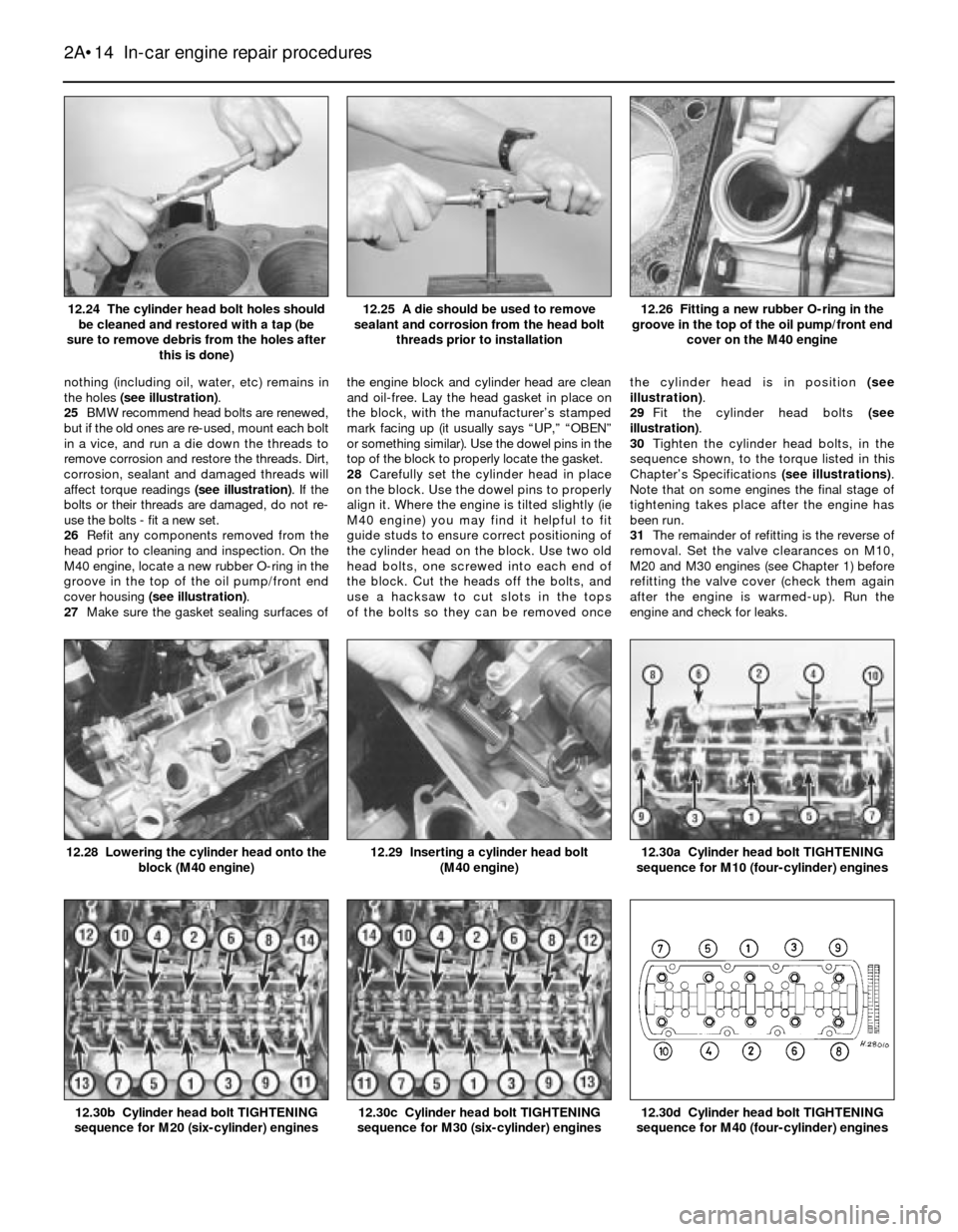
nothing (including oil, water, etc) remains in
the holes (see illustration).
25BMW recommend head bolts are renewed,
but if the old ones are re-used, mount each bolt
in a vice, and run a die down the threads to
remove corrosion and restore the threads. Dirt,
corrosion, sealant and damaged threads will
affect torque readings (see illustration). If the
bolts or their threads are damaged, do not re-
use the bolts - fit a new set.
26Refit any components removed from the
head prior to cleaning and inspection. On the
M40 engine, locate a new rubber O-ring in the
groove in the top of the oil pump/front end
cover housing (see illustration).
27Make sure the gasket sealing surfaces ofthe engine block and cylinder head are clean
and oil-free. Lay the head gasket in place on
the block, with the manufacturer’s stamped
mark facing up (it usually says “UP,” “OBEN”
or something similar). Use the dowel pins in the
top of the block to properly locate the gasket.
28Carefully set the cylinder head in place
on the block. Use the dowel pins to properly
align it. Where the engine is tilted slightly (ie
M40 engine) you may find it helpful to fit
guide studs to ensure correct positioning of
the cylinder head on the block. Use two old
head bolts, one screwed into each end of
the block. Cut the heads off the bolts, and
use a hacksaw to cut slots in the tops
of the bolts so they can be removed oncethe cylinder head is in position (see
illustration).
29Fit the cylinder head bolts (see
illustration).
30Tighten the cylinder head bolts, in the
sequence shown, to the torque listed in this
Chapter’s Specifications (see illustrations).
Note that on some engines the final stage of
tightening takes place after the engine has
been run.
31The remainder of refitting is the reverse of
removal. Set the valve clearances on M10,
M20 and M30 engines (see Chapter 1) before
refitting the valve cover (check them again
after the engine is warmed-up). Run the
engine and check for leaks.
2A•14 In-car engine repair procedures
12.30d Cylinder head bolt TIGHTENING
sequence for M40 (four-cylinder) engines12.30c Cylinder head bolt TIGHTENING
sequence for M30 (six-cylinder) engines12.30b Cylinder head bolt TIGHTENING
sequence for M20 (six-cylinder) engines
12.30a Cylinder head bolt TIGHTENING
sequence for M10 (four-cylinder) engines12.29 Inserting a cylinder head bolt
(M40 engine)12.28 Lowering the cylinder head onto the
block (M40 engine)
12.26 Fitting a new rubber O-ring in the
groove in the top of the oil pump/front end
cover on the M40 engine12.25 A die should be used to remove
sealant and corrosion from the head bolt
threads prior to installation12.24 The cylinder head bolt holes should
be cleaned and restored with a tap (be
sure to remove debris from the holes after
this is done)
Page 63 of 228
36Run the engine and check for leaks and
proper operation of all accessories, then refit
the bonnet and test drive the vehicle.
37Where necessary, have the air
conditioning system recharged and leak-
tested.
6 Engine overhaul- alternatives
The do-it-yourselfer is faced with a number
of options when performing an engine
overhaul. The decision to renew the engine
block, piston/connecting rod assemblies and
crankshaft depends on a number of factors,
with the number one consideration being the
condition of the block. Other considerations
are cost, access to machine shop facilities,
parts availability, time required to complete
the project, and the extent of prior mechanical
experience on the part of the do-it-yourselfer.
Some of the alternatives include:
Individual parts - If the inspection
procedures reveal that the engine block and
most engine components are in re-usable
condition, purchasing individual parts may be
the most economical alternative. The block,
crankshaft and piston/connecting rod
assemblies should all be inspected carefully.
Even if the block shows little wear, the
cylinder bores should be surface-honed.
Crankshaft kit- A crankshaft kit (where
available) consists of a reground crankshaft
with matched undersize new main and
connecting big-end bearings. Sometimes,
reconditioned connecting rods and new
pistons and rings are included with the kit
(such a kit is sometimes called an “engine
kit”). If the block is in good condition, but the
crankshaft journals are scored or worn, a
crankshaft kit and other individual parts may
be the most economical alternative.
Short block- A short block consists of an
engine block with a crankshaft and
piston/connecting rod assemblies already
fitted. New bearings are fitted, and all
clearances will be correct. The existing
camshaft, valve train components, cylinder
head and external parts can be bolted to the
short block with little or no machine shop
work necessary.
Full block - A “full” or “complete” block
consists of a short block plus an oil pump,
sump, cylinder head, valve cover, camshaft
and valve train components, timing sprockets
and chain (or belt) and timing cover. All
components are fitted with new bearings,
seals and gaskets used throughout. The
refitting of manifolds and external parts is all
that’s necessary.
Give careful thought to which alternative is
best for you, and discuss the situation with
local machine shops, parts dealers and
experienced rebuilders before ordering or
purchasing new parts.
7 Engine overhaul-
dismantling sequence
1It’s much easier to dismantle and work on
the engine if it’s mounted on a portable
engine stand. A stand can often be hired quite
cheaply from a tool hire shop. Before the
engine is mounted on a stand, the
flywheel/driveplate should be removed from
the engine.
2If a stand isn’t available, it’s possible to
dismantle the engine with it blocked up on the
floor. Be extra-careful not to tip or drop the
engine when working without a stand.
3If you’re going to obtain a rebuilt engine, all
the external components listed below must
come off first, to be transferred to the new
engine if applicable. This is also the case if
you’re doing a complete engine overhaul
yourself. Note:When removing the external
components from the engine, pay close
attention to details that may be helpful or
important during refitting. Note the fitted
position of gaskets, seals, spacers, pins,
brackets, washers, bolts and other small items.
Alternator and brackets
Emissions control components
Distributor, HT leads and spark plugs
Thermostat and housing cover
Water pump
Fuel injection/carburettor and fuel system
components
Intake and exhaust manifolds
Oil filter and oil pressure sending unit
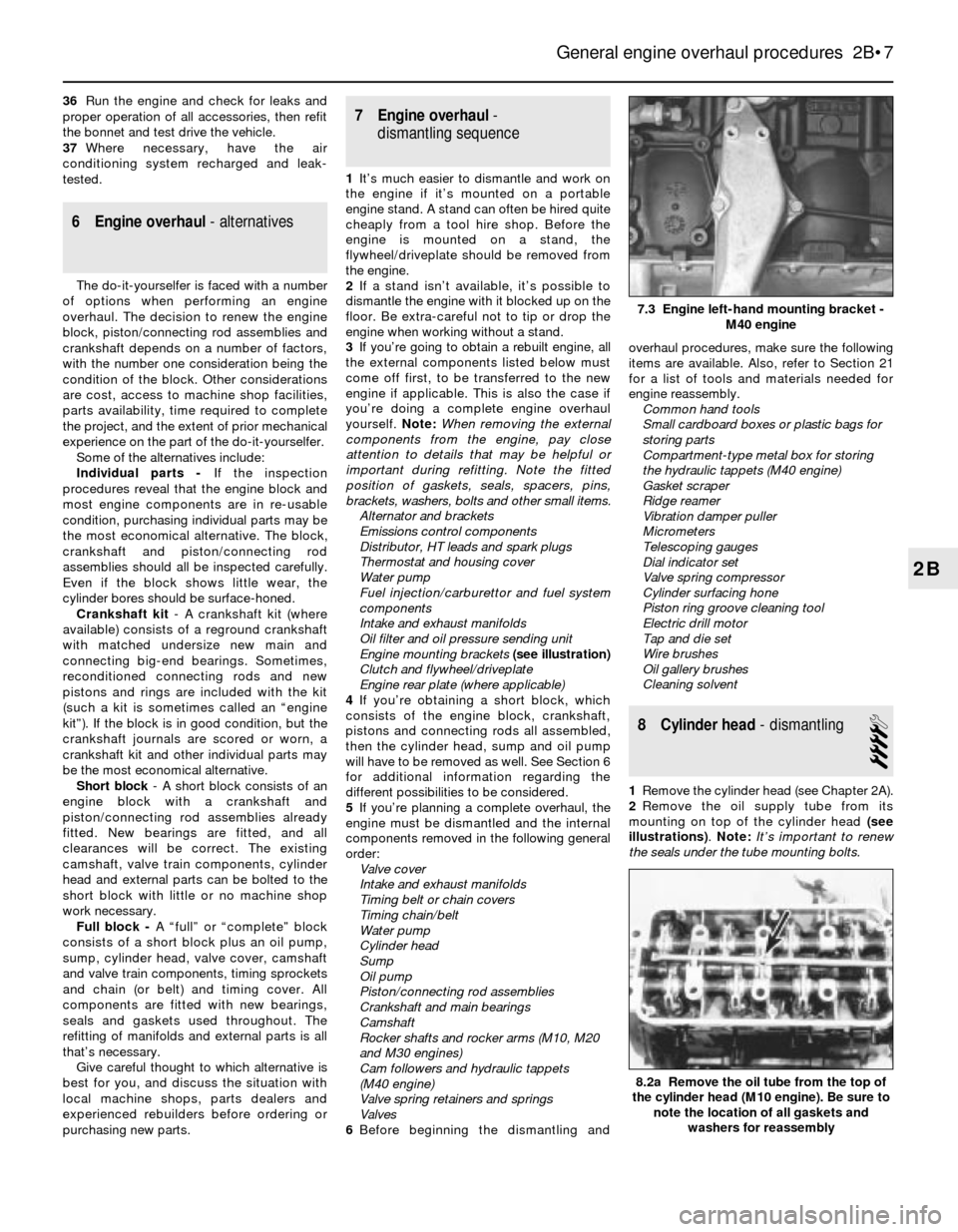
Engine mounting brackets (see illustration)
Clutch and flywheel/driveplate
Engine rear plate (where applicable)
4If you’re obtaining a short block, which
consists of the engine block, crankshaft,
pistons and connecting rods all assembled,
then the cylinder head, sump and oil pump
will have to be removed as well. See Section 6
for additional information regarding the
different possibilities to be considered.
5If you’re planning a complete overhaul, the
engine must be dismantled and the internal
components removed in the following general
order:
Valve cover
Intake and exhaust manifolds
Timing belt or chain covers
Timing chain/belt
Water pump
Cylinder head
Sump
Oil pump
Piston/connecting rod assemblies
Crankshaft and main bearings
Camshaft
Rocker shafts and rocker arms (M10, M20
and M30 engines)
Cam followers and hydraulic tappets
(M40 engine)
Valve spring retainers and springs
Valves
6Before beginning the dismantling andoverhaul procedures, make sure the following
items are available. Also, refer to Section 21
for a list of tools and materials needed for
engine reassembly.
Common hand tools
Small cardboard boxes or plastic bags for
storing parts
Compartment-type metal box for storing
the hydraulic tappets (M40 engine)
Gasket scraper
Ridge reamer
Vibration damper puller
Micrometers
Telescoping gauges
Dial indicator set
Valve spring compressor
Cylinder surfacing hone
Piston ring groove cleaning tool
Electric drill motor
Tap and die set
Wire brushes
Oil gallery brushes
Cleaning solvent
8 Cylinder head- dismantling
4
1Remove the cylinder head (see Chapter 2A).
2Remove the oil supply tube from its
mounting on top of the cylinder head (see
illustrations). Note:It’s important to renew
the seals under the tube mounting bolts.
General engine overhaul procedures 2B•7
7.3 Engine left-hand mounting bracket -
M40 engine
8.2a Remove the oil tube from the top of
the cylinder head (M10 engine). Be sure to
note the location of all gaskets and
washers for reassembly
2B
Page 68 of 228
6If coarse grinding compound is being used,
work only until a dull, matt even surface is
produced on both the valve seat and the
valve, then wipe off the used compound and
repeat the process with fine compound. When
a smooth, unbroken ring of light grey matt
finish is produced on both the valve and seat,
the grinding operation is complete. Do not
grind in the valves any further than absolutely
necessary.
7When all the valves have been ground-in,
carefully wash off all traces of grinding
compound using paraffin or a suitable solvent
before reassembly of the cylinder head.
11 Cylinder head- reassembly
5
1Make sure the cylinder head is spotlessly-
clean before beginning reassembly.
2If the head was sent out for valve servicing,
the valves and related components will
already be in place. Begin the reassembly
procedure with paragraph 8.
3Starting at one end of the head, applymolybdenum disulphide (“moly”) grease or
clean engine oil to each valve stem, and refit
the first valve.
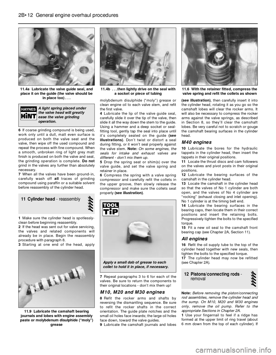
4Lubricate the lip of the valve guide seal,
carefully slide it over the tip of the valve, then
slide it all the way down the stem to the guide.
Using a hammer and a deep socket or seal-
fitting tool, gently tap the seal into place until
it’s completely seated on the guide (see
illustrations). Don’t twist or distort a seal
during fitting, or it won’t seal properly against
the valve stem. Note:On some engines, the
seals for intake and exhaust valves are
different - don’t mix them up.
5Drop the spring seat or shim(s) over the
valve guide, and set the valve spring and
retainer in place.
6Compress the spring with a valve spring
compressor and carefully refit the collets in
the upper groove, then slowly release the
compressor and make sure the collets seat
properly (see illustration).
7Repeat paragraphs 3 to 6 for each of the
valves. Be sure to return the components to
their original locations - don’t mix them up!
M10, M20 and M30 engines
8Refit the rocker arms and shafts by
reversing the dismantling sequence. Be sure
to refit the rocker shafts in the correct
orientation. The guide plate notches and the
small oil holes face inwards; the large oil holes
face down, toward the valve guides.
9Lubricate the camshaft journals and lobes(see illustration), then carefully insert it into
the cylinder head, rotating it as you go so the
camshaft lobes will clear the rocker arms. It
will also be necessary to compress the rocker
arms against the valve springs, as described
in Section 8, so they’ll clear the camshaft
lobes. Be very careful not to scratch or gouge
the camshaft bearing surfaces in the cylinder
head.
M40 engines
10Lubricate the bores for the hydraulic
tappets in the cylinder head, then insert the
tappets in their original positions.
11Locate the thrust discs and cam followers
on the valves and pivot posts in their original
positions.
12Lubricate the bearing surfaces of the
camshaft in the cylinder head.
13Locate the camshaft in the cylinder head
so that the valves of No 1 cylinder are both
open, and the valves of No 4 cylinder are
“rocking” (exhaust closing and inlet opening).
No 1 cylinder is at the timing belt end.
14Lubricate the bearing surfaces in the
bearing caps, then locate them in their correct
positions and insert the retaining bolts.
Progressively tighten the bolts to the specified
torque.
15Fit a new oil seal to the camshaft front
bearing cap (see Chapter 2A, Section 11).
All engines
16Refit the oil supply tube to the top of the
cylinder head together with new seals, then
tighten the bolts to the specified torque.
17The cylinder head may now be refitted
(see Chapter 2A).
12 Pistons/connecting rods-
removal
5
Note:Before removing the piston/connecting
rod assemblies, remove the cylinder head and
the sump. On M10, M20 and M30 engines
only, remove the oil pump. Refer to the
appropriate Sections in Chapter 2A.
1Use your fingernail to feel if a ridge has
formed at the upper limit of ring travel (about
6 mm down from the top of each cylinder). If
2B•12 General engine overhaul procedures
11.9 Lubricate the camshaft bearing
journals and lobes with engine assembly
paste or molybdenum disulphide (“moly”)
grease
11.6 With the retainer fitted, compress the
valve spring and refit the collets as shown 11.4b . . .then lightly drive on the seal with
a socket or piece of tubing11.4a Lubricate the valve guide seal, and
place it on the guide (the valve should be
in place too) . . .
A light spring placed under
the valve head will greatly
ease the valve grinding
operation.
Apply a small dab of grease to each
collet to hold it in place, if necessary.
Page 74 of 228
3When examining the bearings, remove
them from the engine block, the main bearing
caps, the connecting rods and the rod caps,
and lay them out on a clean surface in the
same general position as their location in the
engine. This will enable you to match any
bearing problems with the corresponding
crankshaft journal.
4Dirt and other foreign particles get into the
engine in a variety of ways. It may be left in
the engine during assembly, or it may pass
through filters or the crankcase ventilation
(PCV) system. It may get into the oil, and from
there into the bearings. Metal chips from
machining operations and normal engine wear
are often present. Abrasives are sometimes
left in engine components after recondi-
tioning, especially when parts are not
thoroughly cleaned using the proper cleaning
methods. Whatever the source, these foreign
objects often end up embedded in the soft
bearing material, and are easily recognised.
Large particles will not embed in the bearing,
and will score or gouge the bearing and
journal. The best prevention for this cause of
bearing failure is to clean all parts thoroughly,
and to keep everything spotlessly-clean
during engine assembly. Frequent and regular
engine oil and filter changes are also
recommended.
5Lack of lubrication (or lubrication
breakdown) has a number of interrelated
causes. Excessive heat (which thins the oil),
overloading (which squeezes the oil from the
bearing face) and oil “leakage” or “throw off”
(from excessive bearing clearances, worn oil
pump, or high engine speeds) all contribute to
lubrication breakdown. Blocked oil passages,
which usually are the result of misaligned oil
holes in a bearing shell, will also oil-starve a
bearing and destroy it. When lack of
lubrication is the cause of bearing failure, the
bearing material is wiped or extruded from the
steel backing of the bearing. Temperatures
may increase to the point where the steel
backing turns blue from overheating.
6Driving habits can have a definite effect on
bearing life. Full-throttle, low-speed operation
(labouring the engine) puts very high loads onbearings, which tends to squeeze out the oil
film. These loads cause the bearings to flex,
which produces fine cracks in the bearing
face (fatigue failure). Eventually, the bearing
material will loosen in places, and tear away
from the steel backing. Short-trip driving
leads to corrosion of bearings, because
insufficient engine heat is produced to drive
off the condensation and corrosive gases.
These products collect in the engine oil,
forming acid and sludge. As the oil is carried
to the engine bearings, the acid attacks and
corrodes the bearing material.
7Incorrect bearing refitting during engine
assembly will lead to bearing failure as well.
Tight-fitting bearings leave insufficient bearing
oil clearance, and will result in oil starvation.
Dirt or foreign particles trapped behind a
bearing shell result in high spots on the
bearing, which will lead to failure.
21 Engine overhaul-
reassembly sequence
1Before beginning engine reassembly, make
sure you have all the necessary new parts,
gaskets and seals, as well as the following
items on hand:
Common hand tools
A torque wrench
Piston ring refitting tool
Piston ring compressor
Vibration damper refitting tool
Short lengths of rubber or plastic hose to fit
over connecting rod bolts (where
applicable)
Plastigage
Feeler gauges
A fine-tooth file
New engine oil
Engine assembly oil or molybdenum
disulphide (“moly”) grease
Gasket sealant
Thread-locking compound
2In order to save time and avoid problems,
engine reassembly should be done in the
following general order:Piston rings
Crankshaft and main bearings
Piston/connecting rod assemblies
Oil pump
Sump
Cylinder head assembly
Timing belt or chain and tensioner
assemblies
Water pump
Timing belt or chain covers
Intake and exhaust manifolds
Valve cover
Engine rear plate
Flywheel/driveplate
22 Piston rings- refitting
2
1Before fitting the new piston rings, the ring
end gaps must be checked. It’s assumed that
the piston ring side clearance has been
checked and verified (see Section 18).
2Lay out the piston/connecting rod
assemblies and the new ring sets, so that the
ring sets will be matched with the same piston
and cylinder during the end gap measurement
and engine assembly.
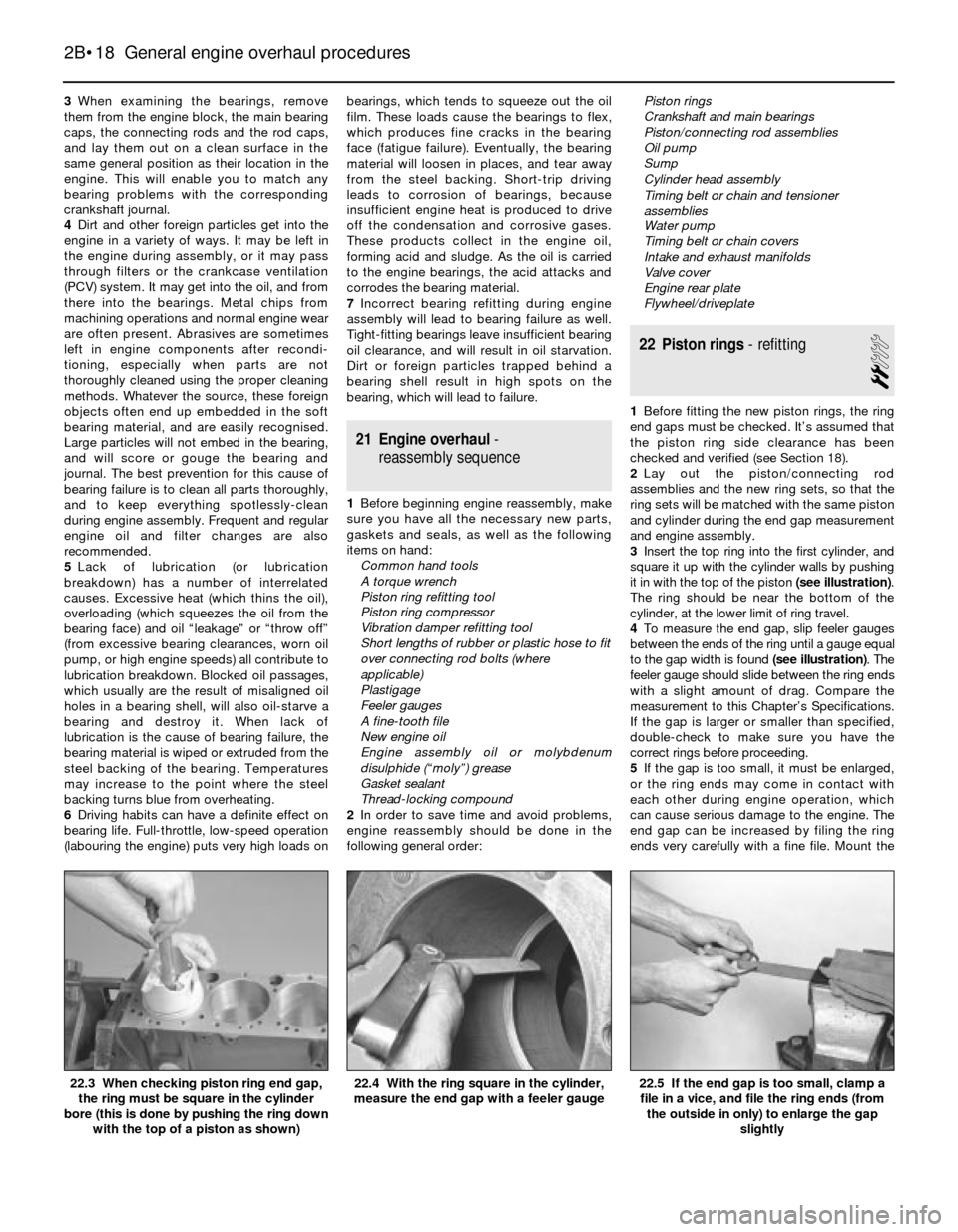
3Insert the top ring into the first cylinder, and
square it up with the cylinder walls by pushing
it in with the top of the piston (see illustration).
The ring should be near the bottom of the
cylinder, at the lower limit of ring travel.
4To measure the end gap, slip feeler gauges
between the ends of the ring until a gauge equal
to the gap width is found(see illustration). The
feeler gauge should slide between the ring ends
with a slight amount of drag. Compare the
measurement to this Chapter’s Specifications.
If the gap is larger or smaller than specified,
double-check to make sure you have the
correct rings before proceeding.
5If the gap is too small, it must be enlarged,
or the ring ends may come in contact with
each other during engine operation, which
can cause serious damage to the engine. The
end gap can be increased by filing the ring
ends very carefully with a fine file. Mount the
2B•18 General engine overhaul procedures
22.5 If the end gap is too small, clamp a
file in a vice, and file the ring ends (from
the outside in only) to enlarge the gap
slightly22.4 With the ring square in the cylinder,
measure the end gap with a feeler gauge22.3 When checking piston ring end gap,
the ring must be square in the cylinder
bore (this is done by pushing the ring down
with the top of a piston as shown)
Page 209 of 228
REF•8General Repair Procedures
Whenever servicing, repair or overhaul work
is carried out on the car or its components,
observe the following procedures and
instructions. This will assist in carrying out the
operation efficiently and to a professional
standard of workmanship.
Joint mating faces and gaskets
When separating components at their
mating faces, never insert screwdrivers or
similar implements into the joint between the
faces in order to prise them apart. This can
cause severe damage which results in oil
leaks, coolant leaks, etc upon reassembly.
Separation is usually achieved by tapping
along the joint with a soft-faced hammer in
order to break the seal. However, note that
this method may not be suitable where
dowels are used for component location.
Where a gasket is used between the mating
faces of two components, a new one must be
fitted on reassembly; fit it dry unless otherwise
stated in the repair procedure. Make sure that
the mating faces are clean and dry, with all
traces of old gasket removed. When cleaning a
joint face, use a tool which is unlikely to score
or damage the face, and remove any burrs or
nicks with an oilstone or fine file.
Make sure that tapped holes are cleaned
with a pipe cleaner, and keep them free of
jointing compound, if this is being used,
unless specifically instructed otherwise.
Ensure that all orifices, channels or pipes
are clear, and blow through them, preferably
using compressed air.
Oil seals
Oil seals can be removed by levering them
out with a wide flat-bladed screwdriver or
similar implement. Alternatively, a number of
self-tapping screws may be screwed into the
seal, and these used as a purchase for pliers or
some similar device in order to pull the seal free.
Whenever an oil seal is removed from its
working location, either individually or as part
of an assembly, it should be renewed.
The very fine sealing lip of the seal is easily
damaged, and will not seal if the surface it
contacts is not completely clean and free from
scratches, nicks or grooves. If the original
sealing surface of the component cannot be
restored, and the manufacturer has not made
provision for slight relocation of the seal
relative to the sealing surface, the component
should be renewed.
Protect the lips of the seal from any surface
which may damage them in the course of
fitting. Use tape or a conical sleeve where
possible. Lubricate the seal lips with oil before
fitting and, on dual-lipped seals, fill the space
between the lips with grease.
Unless otherwise stated, oil seals must be
fitted with their sealing lips toward the
lubricant to be sealed.
Use a tubular drift or block of wood of the
appropriate size to install the seal and, if the
seal housing is shouldered, drive the seal
down to the shoulder. If the seal housing isunshouldered, the seal should be fitted with
its face flush with the housing top face (unless
otherwise instructed).
Screw threads and fastenings
Seized nuts, bolts and screws are quite a
common occurrence where corrosion has set
in, and the use of penetrating oil or releasing
fluid will often overcome this problem if the
offending item is soaked for a while before
attempting to release it. The use of an impact
driver may also provide a means of releasing
such stubborn fastening devices, when used
in conjunction with the appropriate
screwdriver bit or socket. If none of these
methods works, it may be necessary to resort
to the careful application of heat, or the use of
a hacksaw or nut splitter device.
Studs are usually removed by locking two
nuts together on the threaded part, and then
using a spanner on the lower nut to unscrew
the stud. Studs or bolts which have broken off
below the surface of the component in which
they are mounted can sometimes be removed
using a stud extractor. Always ensure that a
blind tapped hole is completely free from oil,
grease, water or other fluid before installing
the bolt or stud. Failure to do this could cause
the housing to crack due to the hydraulic
action of the bolt or stud as it is screwed in.
When tightening a castellated nut to accept
a split pin, tighten the nut to the specified
torque, where applicable, and then tighten
further to the next split pin hole. Never slacken
the nut to align the split pin hole, unless stated
in the repair procedure.
When checking or retightening a nut or bolt
to a specified torque setting, slacken the nut
or bolt by a quarter of a turn, and then
retighten to the specified setting. However,
this should not be attempted where angular
tightening has been used.
For some screw fastenings, notably
cylinder head bolts or nuts, torque wrench
settings are no longer specified for the latter
stages of tightening, “angle-tightening” being
called up instead. Typically, a fairly low torque
wrench setting will be applied to the
bolts/nuts in the correct sequence, followed
by one or more stages of tightening through
specified angles.
Locknuts, locktabs and washers
Any fastening which will rotate against a
component or housing during tightening
should always have a washer between it and
the relevant component or housing.
Spring or split washers should always be
renewed when they are used to lock a critical
component such as a big-end bearing
retaining bolt or nut. Locktabs which are
folded over to retain a nut or bolt should
always be renewed.
Self-locking nuts can be re-used in non-
critical areas, providing resistance can be felt
when the locking portion passes over the bolt
or stud thread. However, it should be noted
that self-locking stiffnuts tend to lose theireffectiveness after long periods of use, and
should then be renewed as a matter of course.
Split pins must always be replaced with
new ones of the correct size for the hole.
When thread-locking compound is found
on the threads of a fastener which is to be re-
used, it should be cleaned off with a wire
brush and solvent, and fresh compound
applied on reassembly.
Special tools
Some repair procedures in this manual
entail the use of special tools such as a press,
two or three-legged pullers, spring com-
pressors, etc. Wherever possible, suitable
readily-available alternatives to the manu-
facturer’s special tools are described, and are
shown in use. In some instances, where no
alternative is possible, it has been necessary
to resort to the use of a manufacturer’s tool,
and this has been done for reasons of safety
as well as the efficient completion of the repair
operation. Unless you are highly-skilled and
have a thorough understanding of the
procedures described, never attempt to
bypass the use of any special tool when the
procedure described specifies its use. Not
only is there a very great risk of personal
injury, but expensive damage could be
caused to the components involved.
Environmental considerations
When disposing of used engine oil, brake
fluid, antifreeze, etc, give due consideration to
any detrimental environmental effects. Do not,
for instance, pour any of the above liquids
down drains into the general sewage system,
or onto the ground to soak away. Many local
council refuse tips provide a facility for waste
oil disposal, as do some garages. If none of
these facilities are available, consult your local
Environmental Health Department, or the
National Rivers Authority, for further advice.
With the universal tightening-up of legis-
lation regarding the emission of environmen-
tally-harmful substances from motor vehicles,
most vehicles have tamperproof devices fitted
to the main adjustment points of the fuel
system. These devices are primarily designed
to prevent unqualified persons from adjusting
the fuel/air mixture, with the chance of a
consequent increase in toxic emissions. If
such devices are found during servicing or
overhaul, they should, wherever possible, be
renewed or refitted in accordance with the
manufacturer’s requirements or current
legislation.
Note: It is
antisocial and
illegal to dump
oil down the
drain. To find
the location of
your local oil
recycling
bank, call this
number free.