knob BMW 3 SERIES 1988 E30 Workshop Manual
[x] Cancel search | Manufacturer: BMW, Model Year: 1988, Model line: 3 SERIES, Model: BMW 3 SERIES 1988 E30Pages: 228, PDF Size: 7.04 MB
Page 85 of 228
4If a new sender unit is to be fitted, make
sure the engine is completely cool. There will
be some coolant loss when the unit is
unscrewed, so be prepared to catch it, or
have the new unit ready to fit immediately the
old one is removed. Disconnect the wiring,
then unscrew the old unit from the engine,
and fit the new one. Use sealant on the
threads. Reconnect the wiring, and check the
coolant level on completion.
9 Heater and air conditioning
blower motor- removal,
testing and refitting
1
Removal
Note: The 3-Series models covered by this
manual have always used a single blower
motor for ventilation, heating and air
conditioning. “Old-shape” (E28) 5-Series
models use two separate blower motors: one
for ventilation and heating, and another for air
conditioning. “New-shape” (E34) 5-Series
models have a single blower motor, like the 3-
Series. The removal and refitting of the single
blower motor, and the old-shape 5-Series
vent/heat motor, is described below. The
removal and refitting of the old-shape 5-Series
air conditioning blower motor is described in
Section 14 of this Chapter.
Caution: If the radio in your
vehicle is equipped with an anti-
theft system, make sure you have
the correct activation code
before disconnecting the battery.
Note: If, after connecting the battery, the
wrong language appears on the instrument
panel display, refer to page 0-7 for the
language resetting procedure.
1Disconnect the battery negative cable.
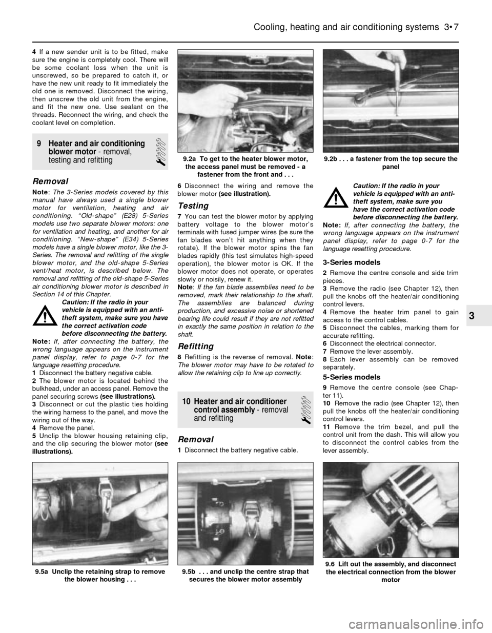
2The blower motor is located behind the
bulkhead, under an access panel. Remove the
panel securing screws (see illustrations).
3Disconnect or cut the plastic ties holding
the wiring harness to the panel, and move the
wiring out of the way.
4Remove the panel.
5Unclip the blower housing retaining clip,
and the clip securing the blower motor (see
illustrations).6Disconnect the wiring and remove the
blower motor (see illustration).
Testing
7You can test the blower motor by applying
battery voltage to the blower motor’s
terminals with fused jumper wires (be sure the
fan blades won’t hit anything when they
rotate). If the blower motor spins the fan
blades rapidly (this test simulates high-speed
operation), the blower motor is OK. If the
blower motor does not operate, or operates
slowly or noisily, renew it.
Note: If the fan blade assemblies need to be
removed, mark their relationship to the shaft.
The assemblies are balanced during
production, and excessive noise or shortened
bearing life could result if they are not refitted
in exactly the same position in relation to the
shaft.
Refitting
8Refitting is the reverse of removal. Note:
The blower motor may have to be rotated to
allow the retaining clip to line up correctly.
10 Heater and air conditioner
control assembly- removal
and refitting
1
Removal
1Disconnect the battery negative cable. Caution: If the radio in your
vehicle is equipped with an anti-
theft system, make sure you
have the correct activation code
before disconnecting the battery.
Note: If, after connecting the battery, the
wrong language appears on the instrument
panel display, refer to page 0-7 for the
language resetting procedure.
3-Series models
2Remove the centre console and side trim
pieces.
3Remove the radio (see Chapter 12), then
pull the knobs off the heater/air conditioning
control levers.
4Remove the heater trim panel to gain
access to the control cables.
5Disconnect the cables, marking them for
accurate refitting.
6Disconnect the electrical connector.
7Remove the lever assembly.
8Each lever assembly can be removed
separately.
5-Series models
9Remove the centre console (see Chap-
ter 11).
10Remove the radio (see Chapter 12), then
pull the knobs off the heater/air conditioning
control levers.
11Remove the trim bezel, and pull the
control unit from the dash. This will allow you
to disconnect the control cables from the
lever assembly.
Cooling, heating and air conditioning systems 3•7
9.5a Unclip the retaining strap to remove
the blower housing . . .
9.2b . . . a fastener from the top secure the
panel9.2a To get to the heater blower motor,
the access panel must be removed - a
fastener from the front and . . .
9.6 Lift out the assembly, and disconnect
the electrical connection from the blower
motor9.5b . . . and unclip the centre strap that
secures the blower motor assembly
3
Page 172 of 228
8 Radio- removal and refitting
1
Caution: If the radio in your
vehicle is equipped with an anti-
theft system, make sure you have
the correct activation code
before disconnecting the battery, Refer to
the information on page 0-7 at the front of
this manual before detaching the cable.
Note: If, after connecting the battery, the
wrong language appears on the instrument
panel display, refer to page 0-7 for the
language resetting procedure.
Removal
1Disconnect the battery negative cable.
2The radios on most models are held in place
by internal clips which are usually located at
the sides or corners of the unit faceplate.
Removal requires a special tool which is
inserted into the holes to release the clips so
the radio can be pulled out. These tools can be
fabricated from heavy wire, or are available
from your dealer or a car audio specialist. On
anti-theft radios, the clips are moved in and
out by internal screws which require another
type of tool. Insert the tool into the holes until
the clips release, then withdraw the radio from
the dash panel. Disconnect the wiring from the
radio and remove it.3On some models, the radio is held in place
by screws located beneath the faceplate. The
control knobs must be pulled off before the
faceplate can be withdrawn.
Refitting
4Refitting is the reverse of removal.
9 Aerial- removal and refitting
1
Caution: If the radio in your
vehicle is equipped with an anti-
theft system, make sure you have
the correct activation code
before disconnecting the battery, Refer to
the information on page 0-7 at the front of
this manual before detaching the cable.
Note: If, after connecting the battery, the
wrong language appears on the instrument
panel display, refer to page 0-7 for the
language resetting procedure.
Removal
1Disconnect the battery negative cable.
2Use circlip pliers to unscrew the aerial
mounting nut.
3Open the boot lid/tailgate and remove the
left side trim panel. On some models, the jack
and tail light cluster cover will have to be
removed first.
4Unplug the aerial power and radio lead
connectors (as applicable), remove the
retaining bolts, and remove the aerial and
motor assembly.
Refitting
5Refitting is the reverse of removal.
10 Instrument cluster-
removal and refitting
2
Caution: The instrument cluster
and components are very
susceptible to damage from
static electricity. Make sure you
are earthed and have dischargedany static electricity (by touching an object
such as a metal water pipe) before
touching the cluster or components.
Caution: If the radio in your
vehicle is equipped with an anti-
theft system, make sure you have
the correct activation code
before disconnecting the battery, Refer to
the information on page 0-7 at the front of
this manual before detaching the cable.
Note: If, after connecting the battery, the
wrong language appears on the instrument
panel display, refer to page 0-7 for the
language resetting procedure.
Removal
1Disconnect the battery negative cable.
2As necessary, remove the steering column
shrouds and lower trim panel (see Chap-
ter 11).
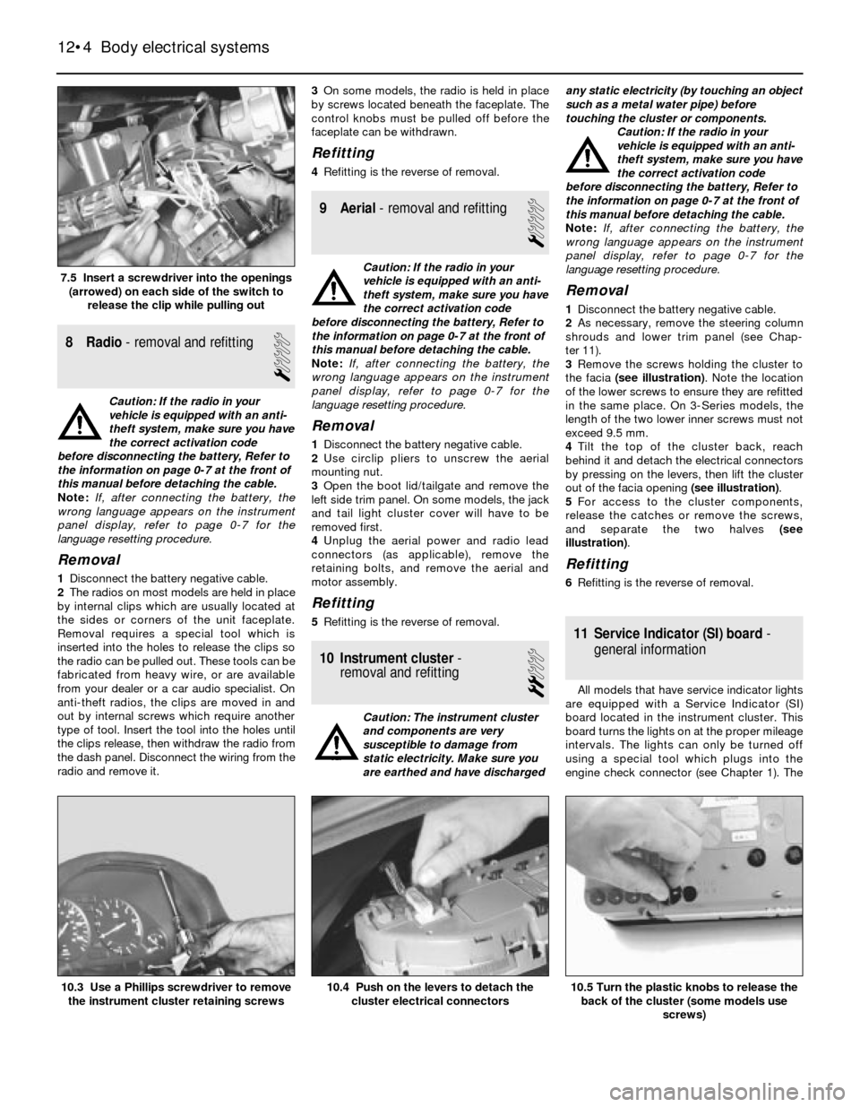
3Remove the screws holding the cluster to
the facia (see illustration). Note the location
of the lower screws to ensure they are refitted
in the same place. On 3-Series models, the
length of the two lower inner screws must not
exceed 9.5 mm.
4Tilt the top of the cluster back, reach
behind it and detach the electrical connectors
by pressing on the levers, then lift the cluster
out of the facia opening (see illustration).
5For access to the cluster components,
release the catches or remove the screws,
and separate the two halves (see
illustration).
Refitting
6Refitting is the reverse of removal.
11 Service Indicator (SI) board-
general information
All models that have service indicator lights
are equipped with a Service Indicator (SI)
board located in the instrument cluster. This
board turns the lights on at the proper mileage
intervals. The lights can only be turned off
using a special tool which plugs into the
engine check connector (see Chapter 1). The
12•4 Body electrical systems
10.5 Turn the plastic knobs to release the
back of the cluster (some models use
screws)10.4 Push on the levers to detach the
cluster electrical connectors10.3 Use a Phillips screwdriver to remove
the instrument cluster retaining screws
7.5 Insert a screwdriver into the openings
(arrowed) on each side of the switch to
release the clip while pulling out