schematic BMW 3 SERIES 1988 E30 Workshop Manual
[x] Cancel search | Manufacturer: BMW, Model Year: 1988, Model line: 3 SERIES, Model: BMW 3 SERIES 1988 E30Pages: 228, PDF Size: 7.04 MB
Page 116 of 228

connect the ohmmeter to coil terminal 1 (-)
and the centre tower. On Motronic systems,
connect the ohmmeter to coil terminal 15 (+)
and the centre tower. Compare the measured
resistance with the values given in the Specifi-
cations in this Chapter.
6If the measured resistances are not close to
those specified, the coil is defective and
should be renewed. Note that the measured
resistance will vary according to the
temperature of the coil, so don’t rush to
condemn the coil if the resistance is only a
little way out.
7It is essential for proper ignition system
operation that all coil terminals and wire leads
be kept clean and dry.
8Refit the coil in its mounting, and reconnect
the wiring. Refitting is the reverse of removal.
10 Impulse generator and
ignition control unit- check
and renewal (TCI system)
3
1The impulse generator (located in the
distributor) and ignition control unit need to be
tested in the event there is no spark at the
spark plugs. Make sure the plug leads,
ignition coil and spark plugs are working
properly (see Sections 6 and 9). There are two
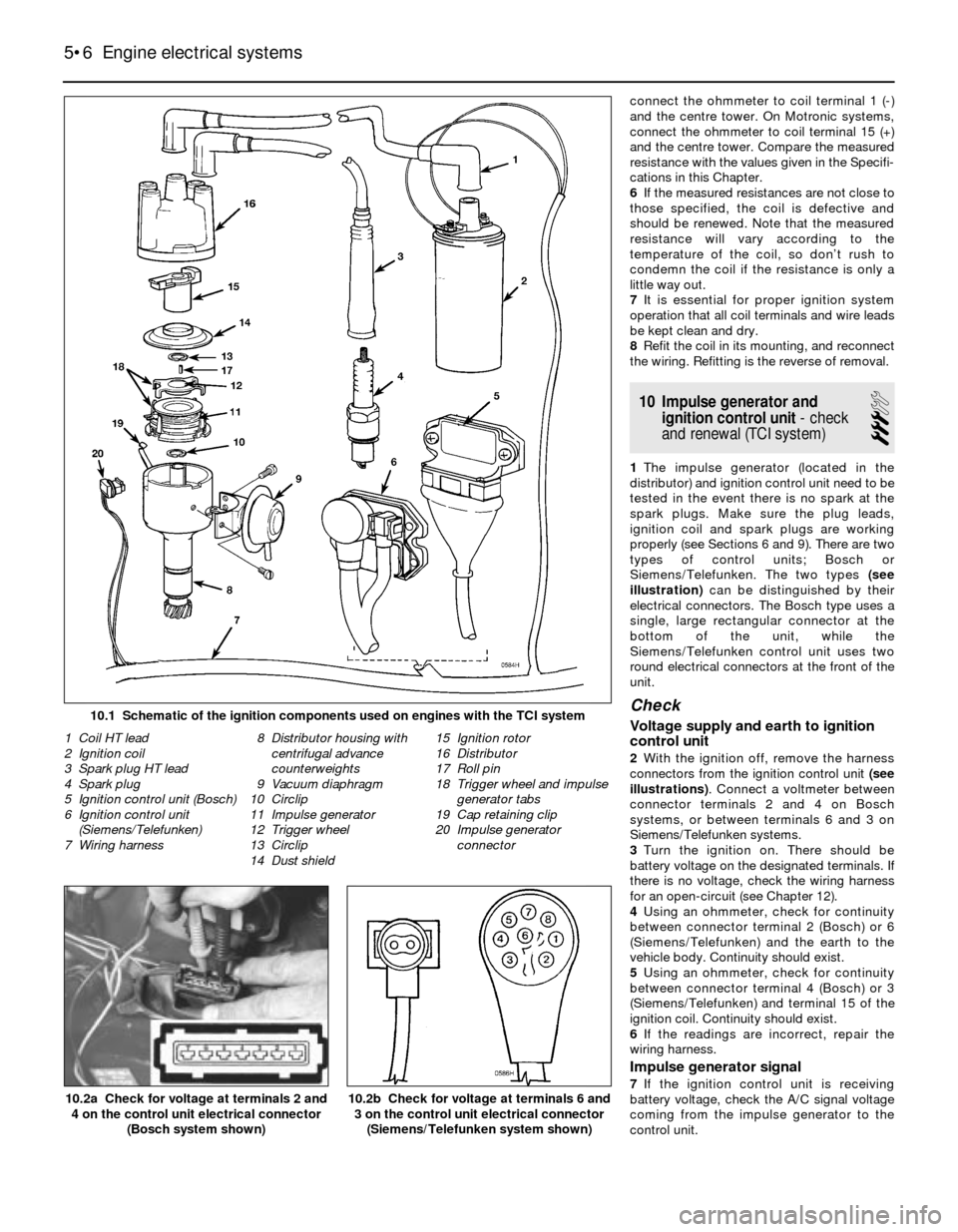
types of control units; Bosch or
Siemens/Telefunken. The two types (see
illustration)can be distinguished by their
electrical connectors. The Bosch type uses a
single, large rectangular connector at the
bottom of the unit, while the
Siemens/Telefunken control unit uses two
round electrical connectors at the front of the
unit.
Check
Voltage supply and earth to ignition
control unit
2With the ignition off, remove the harness
connectors from the ignition control unit (see
illustrations). Connect a voltmeter between
connector terminals 2 and 4 on Bosch
systems, or between terminals 6 and 3 on
Siemens/Telefunken systems.
3Turn the ignition on. There should be
battery voltage on the designated terminals. If
there is no voltage, check the wiring harness
for an open-circuit (see Chapter 12).
4Using an ohmmeter, check for continuity
between connector terminal 2 (Bosch) or 6
(Siemens/Telefunken) and the earth to the
vehicle body. Continuity should exist.
5Using an ohmmeter, check for continuity
between connector terminal 4 (Bosch) or 3
(Siemens/Telefunken) and terminal 15 of the
ignition coil. Continuity should exist.
6If the readings are incorrect, repair the
wiring harness.
Impulse generator signal
7If the ignition control unit is receiving
battery voltage, check the A/C signal voltage
coming from the impulse generator to the
control unit.
5•6 Engine electrical systems
10.2b Check for voltage at terminals 6 and
3 on the control unit electrical connector
(Siemens/Telefunken system shown)10.2a Check for voltage at terminals 2 and
4 on the control unit electrical connector
(Bosch system shown)
1 Coil HT lead
2 Ignition coil
3 Spark plug HT lead
4 Spark plug
5 Ignition control unit (Bosch)
6 Ignition control unit
(Siemens/Telefunken)
7 Wiring harness8 Distributor housing with
centrifugal advance
counterweights
9 Vacuum diaphragm
10 Circlip
11 Impulse generator
12 Trigger wheel
13 Circlip
14 Dust shield15 Ignition rotor
16 Distributor
17 Roll pin
18 Trigger wheel and impulse
generator tabs
19 Cap retaining clip
20 Impulse generator
connector
10.1 Schematic of the ignition components used on engines with the TCI system