hazard switch BMW 3 SERIES 1989 E30 Workshop Manual
[x] Cancel search | Manufacturer: BMW, Model Year: 1989, Model line: 3 SERIES, Model: BMW 3 SERIES 1989 E30Pages: 228, PDF Size: 7.04 MB
Page 6 of 228
0•6Safety First!
Working on your car can be dangerous.
This page shows just some of the potential
risks and hazards, with the aim of creating a
safety-conscious attitude.
General hazards
Scalding
• Don’t remove the radiator or expansion
tank cap while the engine is hot.
• Engine oil, automatic transmission fluid or
power steering fluid may also be dangerously
hot if the engine has recently been running.
Burning
• Beware of burns from the exhaust system
and from any part of the engine. Brake discs
and drums can also be extremely hot
immediately after use.
Crushing
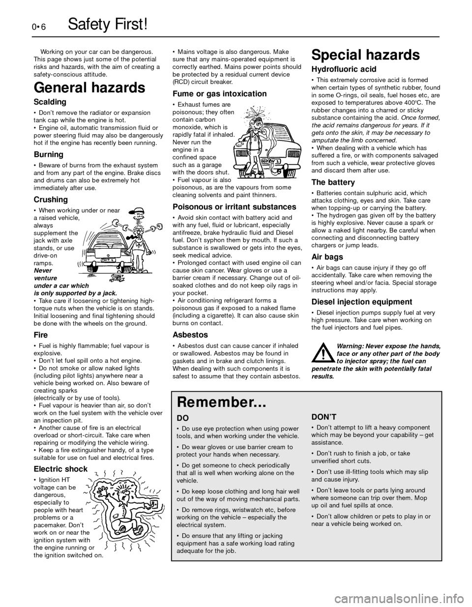
• When working under or near
a raised vehicle,
always
supplement the
jack with axle
stands, or use
drive-on
ramps.
Never
venture
under a car which
is only supported by a jack.
• Take care if loosening or tightening high-
torque nuts when the vehicle is on stands.
Initial loosening and final tightening should
be done with the wheels on the ground.
Fire
• Fuel is highly flammable; fuel vapour is
explosive.
• Don’t let fuel spill onto a hot engine.
• Do not smoke or allow naked lights
(including pilot lights) anywhere near a
vehicle being worked on. Also beware of
creating sparks
(electrically or by use of tools).
• Fuel vapour is heavier than air, so don’t
work on the fuel system with the vehicle over
an inspection pit.
• Another cause of fire is an electrical
overload or short-circuit. Take care when
repairing or modifying the vehicle wiring.
• Keep a fire extinguisher handy, of a type
suitable for use on fuel and electrical fires.
Electric shock
• Ignition HT
voltage can be
dangerous,
especially to
people with heart
problems or a
pacemaker. Don’t
work on or near the
ignition system with
the engine running or
the ignition switched on.• Mains voltage is also dangerous. Make
sure that any mains-operated equipment is
correctly earthed. Mains power points should
be protected by a residual current device
(RCD) circuit breaker.
Fume or gas intoxication
• Exhaust fumes are
poisonous; they often
contain carbon
monoxide, which is
rapidly fatal if inhaled.
Never run the
engine in a
confined space
such as a garage
with the doors shut.
• Fuel vapour is also
poisonous, as are the vapours from some
cleaning solvents and paint thinners.
Poisonous or irritant substances
• Avoid skin contact with battery acid and
with any fuel, fluid or lubricant, especially
antifreeze, brake hydraulic fluid and Diesel
fuel. Don’t syphon them by mouth. If such a
substance is swallowed or gets into the eyes,
seek medical advice.
• Prolonged contact with used engine oil can
cause skin cancer. Wear gloves or use a
barrier cream if necessary. Change out of oil-
soaked clothes and do not keep oily rags in
your pocket.
• Air conditioning refrigerant forms a
poisonous gas if exposed to a naked flame
(including a cigarette). It can also cause skin
burns on contact.
Asbestos
• Asbestos dust can cause cancer if inhaled
or swallowed. Asbestos may be found in
gaskets and in brake and clutch linings.
When dealing with such components it is
safest to assume that they contain asbestos.
Special hazards
Hydrofluoric acid
• This extremely corrosive acid is formed
when certain types of synthetic rubber, found
in some O-rings, oil seals, fuel hoses etc, are
exposed to temperatures above 400
0C. The
rubber changes into a charred or sticky
substance containing the acid. Once formed,
the acid remains dangerous for years. If it
gets onto the skin, it may be necessary to
amputate the limb concerned.
• When dealing with a vehicle which has
suffered a fire, or with components salvaged
from such a vehicle, wear protective gloves
and discard them after use.
The battery
• Batteries contain sulphuric acid, which
attacks clothing, eyes and skin. Take care
when topping-up or carrying the battery.
• The hydrogen gas given off by the battery
is highly explosive. Never cause a spark or
allow a naked light nearby. Be careful when
connecting and disconnecting battery
chargers or jump leads.
Air bags
• Air bags can cause injury if they go off
accidentally. Take care when removing the
steering wheel and/or facia. Special storage
instructions may apply.
Diesel injection equipment
• Diesel injection pumps supply fuel at very
high pressure. Take care when working on
the fuel injectors and fuel pipes.
Warning: Never expose the hands,
face or any other part of the body
to injector spray; the fuel can
penetrate the skin with potentially fatal
results.
Remember...
DO
• Do use eye protection when using power
tools, and when working under the vehicle.
• Do wear gloves or use barrier cream to
protect your hands when necessary.
• Do get someone to check periodically
that all is well when working alone on the
vehicle.
• Do keep loose clothing and long hair well
out of the way of moving mechanical parts.
• Do remove rings, wristwatch etc, before
working on the vehicle – especially the
electrical system.
• Do ensure that any lifting or jacking
equipment has a safe working load rating
adequate for the job.
A few tips
DON’T
• Don’t attempt to lift a heavy component
which may be beyond your capability – get
assistance.
• Don’t rush to finish a job, or take
unverified short cuts.
• Don’t use ill-fitting tools which may slip
and cause injury.
• Don’t leave tools or parts lying around
where someone can trip over them. Mop
up oil and fuel spills at once.
• Don’t allow children or pets to play in or
near a vehicle being worked on.
Page 21 of 228
Every 6000 miles or 6 months, whichever comes first
1•11
6.17a Unscrew the bolt . . .
1
Every 6000 miles
6 Engine oil and filter change
1
Warning: Prolonged skin contact
with used engine oil is
hazardous. Use a barrier cream
and wear gloves during this procedure.
Change out of oil-soaked clothing
immediately.
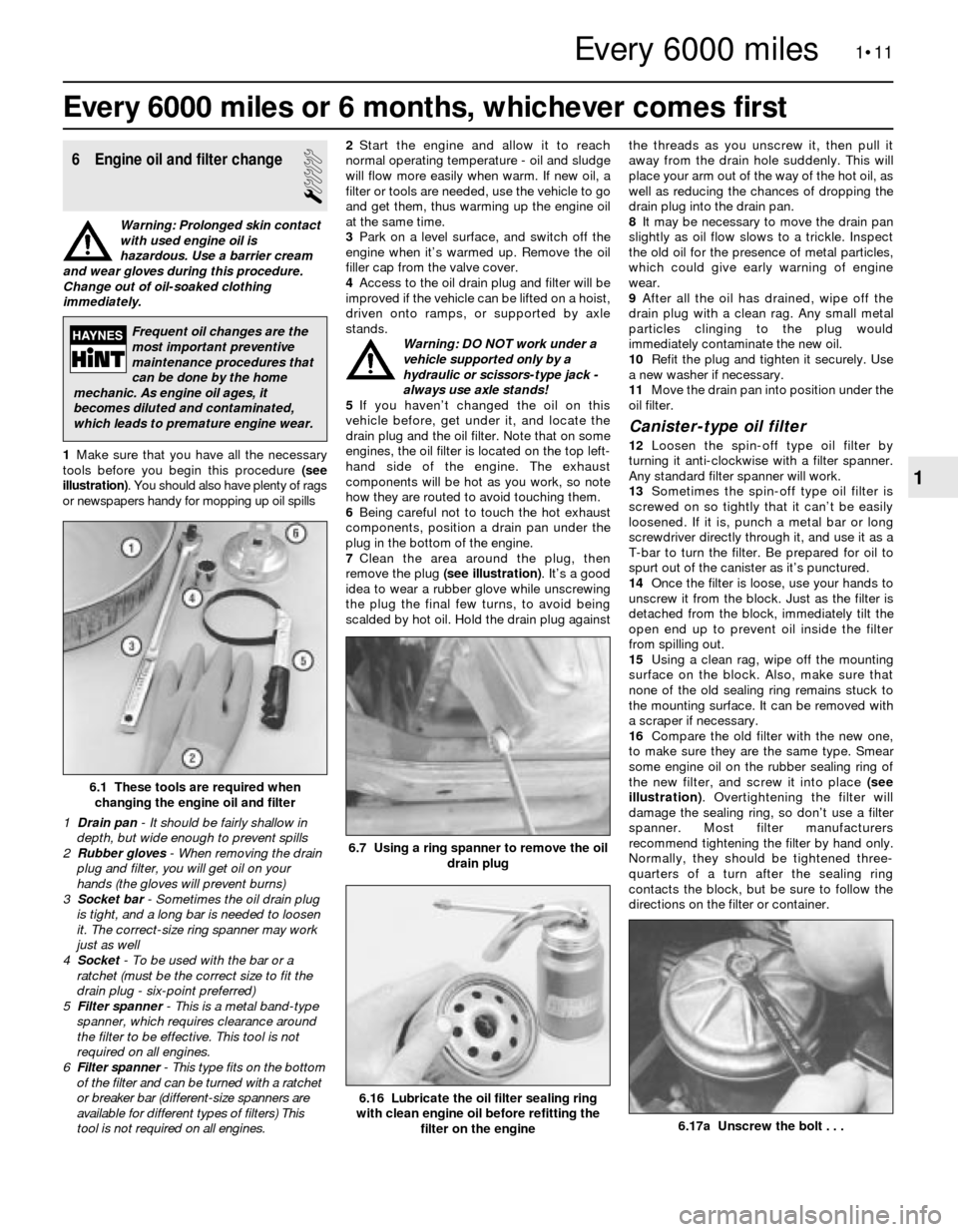
1Make sure that you have all the necessary
tools before you begin this procedure (see
illustration). You should also have plenty of rags
or newspapers handy for mopping up oil spills2Start the engine and allow it to reach
normal operating temperature - oil and sludge
will flow more easily when warm. If new oil, a
filter or tools are needed, use the vehicle to go
and get them, thus warming up the engine oil
at the same time.
3Park on a level surface, and switch off the
engine when it’s warmed up. Remove the oil
filler cap from the valve cover.
4Access to the oil drain plug and filter will be
improved if the vehicle can be lifted on a hoist,
driven onto ramps, or supported by axle
stands.
Warning: DO NOT work under a
vehicle supported only by a
hydraulic or scissors-type jack -
always use axle stands!
5If you haven’t changed the oil on this
vehicle before, get under it, and locate the
drain plug and the oil filter. Note that on some
engines, the oil filter is located on the top left-
hand side of the engine. The exhaust
components will be hot as you work, so note
how they are routed to avoid touching them.
6Being careful not to touch the hot exhaust
components, position a drain pan under the
plug in the bottom of the engine.
7Clean the area around the plug, then
remove the plug (see illustration). It’s a good
idea to wear a rubber glove while unscrewing
the plug the final few turns, to avoid being
scalded by hot oil. Hold the drain plug againstthe threads as you unscrew it, then pull it
away from the drain hole suddenly. This will
place your arm out of the way of the hot oil, as
well as reducing the chances of dropping the
drain plug into the drain pan.
8It may be necessary to move the drain pan
slightly as oil flow slows to a trickle. Inspect
the old oil for the presence of metal particles,
which could give early warning of engine
wear.
9After all the oil has drained, wipe off the
drain plug with a clean rag. Any small metal
particles clinging to the plug would
immediately contaminate the new oil.
10Refit the plug and tighten it securely. Use
a new washer if necessary.
11Move the drain pan into position under the
oil filter.
Canister-type oil filter
12Loosen the spin-off type oil filter by
turning it anti-clockwise with a filter spanner.
Any standard filter spanner will work.
13Sometimes the spin-off type oil filter is
screwed on so tightly that it can’t be easily
loosened. If it is, punch a metal bar or long
screwdriver directly through it, and use it as a
T-bar to turn the filter. Be prepared for oil to
spurt out of the canister as it’s punctured.
14Once the filter is loose, use your hands to
unscrew it from the block. Just as the filter is
detached from the block, immediately tilt the
open end up to prevent oil inside the filter
from spilling out.
15Using a clean rag, wipe off the mounting
surface on the block. Also, make sure that
none of the old sealing ring remains stuck to
the mounting surface. It can be removed with
a scraper if necessary.
16Compare the old filter with the new one,
to make sure they are the same type. Smear
some engine oil on the rubber sealing ring of
the new filter, and screw it into place (see
illustration). Overtightening the filter will
damage the sealing ring, so don’t use a filter
spanner. Most filter manufacturers
recommend tightening the filter by hand only.
Normally, they should be tightened three-
quarters of a turn after the sealing ring
contacts the block, but be sure to follow the
directions on the filter or container.
6.1 These tools are required when
changing the engine oil and filter
1 Drain pan- It should be fairly shallow in
depth, but wide enough to prevent spills
2 Rubber gloves- When removing the drain
plug and filter, you will get oil on your
hands (the gloves will prevent burns)
3 Socket bar - Sometimes the oil drain plug
is tight, and a long bar is needed to loosen
it. The correct-size ring spanner may work
just as well
4 Socket- To be used with the bar or a
ratchet (must be the correct size to fit the
drain plug - six-point preferred)
5 Filter spanner - This is a metal band-type
spanner, which requires clearance around
the filter to be effective. This tool is not
required on all engines.
6 Filter spanner- This type fits on the bottom
of the filter and can be turned with a ratchet
or breaker bar (different-size spanners are
available for different types of filters) This
tool is not required on all engines.
6.7 Using a ring spanner to remove the oil
drain plug
6.16 Lubricate the oil filter sealing ring
with clean engine oil before refitting the
filter on the engine
Frequent oil changes are the
most important preventive
maintenance procedures that
can be done by the home
mechanic. As engine oil ages, it
becomes diluted and contaminated,
which leads to premature engine wear.
Page 32 of 228
no cause for concern. Make sure that any fluid
noted is from the struts/shocks, and not from
any other source. If leakage is noted, renew
the struts or shock absorbers in axle pairs (or
as a full set).
7Check the struts/shock absorbers to be
sure that they are securely mounted and
undamaged. Check the upper mountings for
damage and wear. If damage or wear is
noted, renew the struts or shock absorbers.
8If the struts or shock absorbers must be
renewed, refer to Chapter 10 for the
procedure. Always renew both units on the
same axle, or the safety of the vehicle may be
compromised. If possible, renew all four as a
set.
Steering and suspension check
9Inspect the steering system components
for damage and distortion. Look for leaks and
damaged seals, boots and fittings.
10Clean the lower end of the steering
knuckle. Have an assistant grasp the lower
edge of the tyre and move the wheel in and
out, while you look for movement at the
steering knuckle-to-axle arm balljoints.
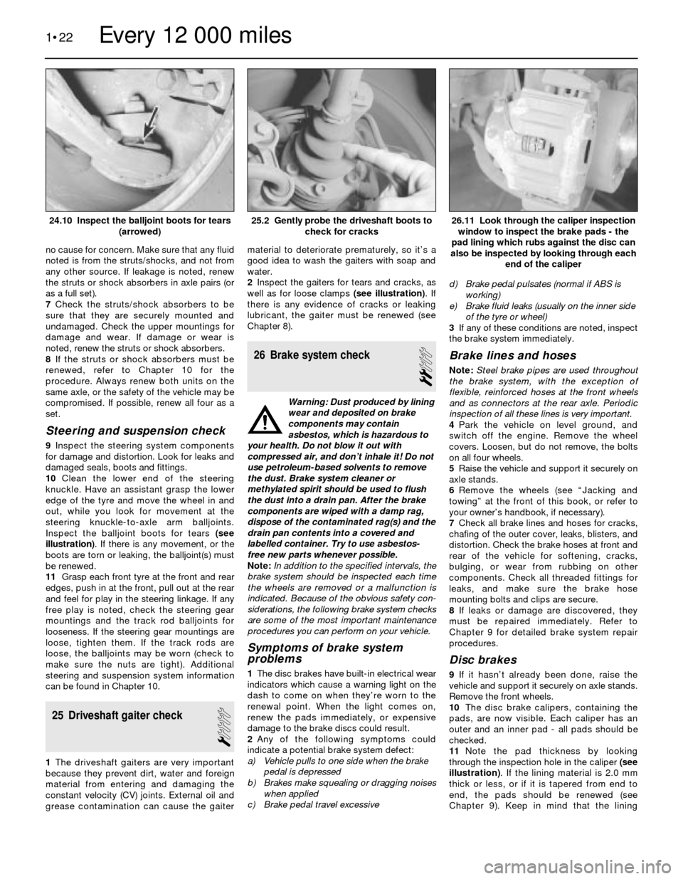
Inspect the balljoint boots for tears (see
illustration). If there is any movement, or the
boots are torn or leaking, the balljoint(s) must
be renewed.
11Grasp each front tyre at the front and rear
edges, push in at the front, pull out at the rear
and feel for play in the steering linkage. If any
free play is noted, check the steering gear
mountings and the track rod balljoints for
looseness. If the steering gear mountings are
loose, tighten them. If the track rods are
loose, the balljoints may be worn (check to
make sure the nuts are tight). Additional
steering and suspension system information
can be found in Chapter 10.
25 Driveshaft gaiter check
1
1The driveshaft gaiters are very important
because they prevent dirt, water and foreign
material from entering and damaging the
constant velocity (CV) joints. External oil and
grease contamination can cause the gaitermaterial to deteriorate prematurely, so it’s a
good idea to wash the gaiters with soap and
water.
2Inspect the gaiters for tears and cracks, as
well as for loose clamps (see illustration). If
there is any evidence of cracks or leaking
lubricant, the gaiter must be renewed (see
Chapter 8).
26 Brake system check
2
Warning: Dust produced by lining
wear and deposited on brake
components may contain
asbestos, which is hazardous to
your health. Do not blow it out with
compressed air, and don’t inhale it! Do not
use petroleum-based solvents to remove
the dust. Brake system cleaner or
methylated spirit should be used to flush
the dust into a drain pan. After the brake
components are wiped with a damp rag,
dispose of the contaminated rag(s) and the
drain pan contents into a covered and
labelled container. Try to use asbestos-
free new parts whenever possible.
Note:In addition to the specified intervals, the
brake system should be inspected each time
the wheels are removed or a malfunction is
indicated. Because of the obvious safety con-
siderations, the following brake system checks
are some of the most important maintenance
procedures you can perform on your vehicle.
Symptoms of brake system
problems
1The disc brakes have built-in electrical wear
indicators which cause a warning light on the
dash to come on when they’re worn to the
renewal point. When the light comes on,
renew the pads immediately, or expensive
damage to the brake discs could result.
2Any of the following symptoms could
indicate a potential brake system defect:
a) Vehicle pulls to one side when the brake
pedal is depressed
b) Brakes make squealing or dragging noises
when applied
c) Brake pedal travel excessived) Brake pedal pulsates (normal if ABS is
working)
e) Brake fluid leaks (usually on the inner side
of the tyre or wheel)
3If any of these conditions are noted, inspect
the brake system immediately.
Brake lines and hoses
Note: Steel brake pipes are used throughout
the brake system, with the exception of
flexible, reinforced hoses at the front wheels
and as connectors at the rear axle. Periodic
inspection of all these lines is very important.
4Park the vehicle on level ground, and
switch off the engine. Remove the wheel
covers. Loosen, but do not remove, the bolts
on all four wheels.
5Raise the vehicle and support it securely on
axle stands.
6Remove the wheels (see “Jacking and
towing” at the front of this book, or refer to
your owner’s handbook, if necessary).
7Check all brake lines and hoses for cracks,
chafing of the outer cover, leaks, blisters, and
distortion. Check the brake hoses at front and
rear of the vehicle for softening, cracks,
bulging, or wear from rubbing on other
components. Check all threaded fittings for
leaks, and make sure the brake hose
mounting bolts and clips are secure.
8If leaks or damage are discovered, they
must be repaired immediately. Refer to
Chapter 9 for detailed brake system repair
procedures.
Disc brakes
9If it hasn’t already been done, raise the
vehicle and support it securely on axle stands.
Remove the front wheels.
10The disc brake calipers, containing the
pads, are now visible. Each caliper has an
outer and an inner pad - all pads should be
checked.
11Note the pad thickness by looking
through the inspection hole in the caliper (see
illustration). If the lining material is 2.0 mm
thick or less, or if it is tapered from end to
end, the pads should be renewed (see
Chapter 9). Keep in mind that the lining
1•22
26.11 Look through the caliper inspection
window to inspect the brake pads - the
pad lining which rubs against the disc can
also be inspected by looking through each
end of the caliper25.2 Gently probe the driveshaft boots to
check for cracks24.10 Inspect the balljoint boots for tears
(arrowed)
Every 12 000 miles
Page 169 of 228
12
Chapter 12 Body electrical systems
Bulb renewal . . . . . . . . . . . . . . . . . . . . . . . . . . . . . . . . . . . . . . . . . . . 15
Central locking system - description and check . . . . . . . . . . . . . . . . 20
Cruise control system - description and check . . . . . . . . . . . . . . . . 19
Direction indicator/hazard warning flasher - check and renewal . . . 5
Electric windows - description and check . . . . . . . . . . . . . . . . . . . . 21
Electrical system fault finding - general information . . . . . . . . . . . . . 2
Fuses - general information . . . . . . . . . . . . . . . . . . . . . . . . . . . . . . . 3
General information . . . . . . . . . . . . . . . . . . . . . . . . . . . . . . . . . . . . . . 1
Headlight housing - removal and refitting . . . . . . . . . . . . . . . . . . . . . 14
Headlights - adjustment . . . . . . . . . . . . . . . . . . . . . . . . . . . . . . . . . . 13
Headlights - bulb renewal . . . . . . . . . . . . . . . . . . . . . . . . . . . . . . . . . 12Heated rear window - check and repair . . . . . . . . . . . . . . . . . . . . . . 17
Ignition switch - removal and refitting . . . . . . . . . . . . . . . . . . . . . . . . 7
Instrument cluster - removal and refitting . . . . . . . . . . . . . . . . . . . . . 10
Radio - removal and refitting . . . . . . . . . . . . . . . . . . . . . . . . . . . . . . . 8
Radio aerial - removal and refitting . . . . . . . . . . . . . . . . . . . . . . . . . . 9
Relays - general information . . . . . . . . . . . . . . . . . . . . . . . . . . . . . . . 4
Service Indicator (SI) board - general information . . . . . . . . . . . . . . 11
Steering column switches - removal and refitting . . . . . . . . . . . . . . . 6
Supplemental Restraint System (SRS) - general information . . . . . . 18
Windscreen/tailgate wiper motor - removal and refitting . . . . . . . . . 16
Wiring diagrams - general information . . . . . . . . . . . . . . . . . . . . . . . 22
12•1
Easy,suitable for
novice with little
experienceFairly easy,suitable
for beginner with
some experienceFairly difficult,
suitable for competent
DIY mechanic
Difficult,suitable for
experienced DIY
mechanicVery difficult,
suitable for expert
DIY or professional
Degrees of difficulty Contents
1 General information
The chassis electrical system of this vehicle
is of 12-volt, negative earth type. Power for
the lights and all electrical accessories is
supplied by a lead/acid-type battery, which is
charged by the alternator.
This Chapter covers repair and service
procedures for various chassis (non-engine
related) electrical components. For
information regarding the engine electrical
system components (battery, alternator,
distributor and starter motor), see Chapter 5.
Warning: To prevent electrical
short-circuits, fires and injury,
always disconnect the battery
negative terminal before
checking, repairing or renewing electrical
components.
Caution: If the radio in your
vehicle is equipped with an anti-
theft system, make sure you have
the correct activation code
before disconnecting the battery, Refer to
the information on page 0-7 at the front of
this manual before detaching the cable.
Note: If, after connecting the battery, the
wrong language appears on the instrument
panel display, refer to page 0-7 for the
language resetting procedure.
2 Electrical system fault
finding- general information
2
A typical electrical circuit consists of an
electrical component, any switches, relays,
motors, fuses, fusible links or circuit breakers,
etc related to that component, and the wiring
and connectors that link the components to
both the battery and the chassis. To help you
pinpoint an electrical circuit problem, wiring
diagrams are included at the end of this book.
Before tackling any troublesome electrical
circuit, first study the appropriate wiring
diagrams to get a complete understanding of
what makes up that individual circuit.
Troublespots, for instance, can often be
isolated by noting if other components related
to that circuit are routed through the same
fuse and earth connections.
Electrical problems usually stem from
simple causes such as loose or corroded
connectors, a blown fuse, a melted fusible
link, or a bad relay. Inspect all fuses, wires
and connectors in a problem circuit first.
The basic tools needed include a circuit
tester, a high-impedance digital voltmeter, a
continuity tester and a jumper wire with an in-
line circuit breaker for bypassing electrical
components. Before attempting to locate or
define a problem with electrical testinstruments, use the wiring diagrams to
decide where to make the necessary
connections.
Voltage checks
Perform a voltage check first when a circuit
is not functioning properly. Connect one lead
of a circuit tester to either the negative battery
terminal or a known good earth.
Connect the other lead to a connector in
the circuit being tested, preferably nearest to
the battery or fuse. If the bulb of the tester
lights up, voltage is present, which means that
the part of the circuit between the connector
and the battery is problem-free. Continue
checking the rest of the circuit in the same
fashion.
When you reach a point at which no voltage
is present, the problem lies between that point
and the last test point with voltage. Most of
the time, problems can be traced to a loose
connection.Note:Keep in mind that some
circuits receive voltage only when the ignition
key is turned to a certain position.
Electrical fault diagnosis is simple if you
keep in mind that all electrical circuits are
basically electricity running from the battery,
through the wires, switches, relays, fuses and
fusible links to each electrical component
(light bulb, motor, etc) and then to earth, from
where it is passed back to the battery. Any
electrical problem is an interruption in the flow
of electricity to and from the battery.
Page 170 of 228
Finding a short-circuit
One method of finding a short-circuit is to
remove the fuse and connect a test light or
voltmeter in its place. There should be no
voltage present in the circuit. Move the
electrical connectors from side-to-side while
watching the test light. If the bulb goes on,
there is a short to earth somewhere in that
area, probably where the insulation has been
rubbed through. The same test can be
performed on each component in a circuit,
even a switch.
Earth check
Perform a earth check to see whether a
component is properly earthed (passing
current back via the vehicle body). Disconnect
the battery, and connect one lead of a self-
powered test light (often known as a
continuity tester) to a known good earth.
Connect the other lead to the wire or earth
connection being tested. The bulb should
light, indicating a good earth connection. If
not, dismantle the connection, and clean all
relevant parts thoroughly. When re-making
the connection, use serrated (shakeproof)
washers if possible, and tighten all bolts, etc,
securely.
Caution: If the radio in your
vehicle is equipped with an anti-
theft system, make sure you have
the correct activation code
before disconnecting the battery, Refer to
the information on page 0-7 at the front of
this manual before detaching the cable.
Note: If, after connecting the battery, the
wrong language appears on the instrument
panel display, refer to page 0-7 for the
language resetting procedure.
Continuity check
A continuity check determines if there are
any breaks in a circuit - if it is conducting
electricity properly. With the circuit off (no
power in the circuit), a self-powered continuity
tester can be used to check the circuit.
Connect the test leads to both ends of the
circuit, and if the test light comes on, the
circuit is passing current properly. If the light
doesn’t come on, there is a break somewhere
in the circuit. The same procedure can be
used to test a switch, by connecting the
continuity tester to the power-in and power-
out sides of the switch. With the switch turned
on, the test light should come on.
Finding an open-circuit
When diagnosing for possible open-
circuits, it is often difficult to locate them by
sight, because oxidation or terminal
misalignment are hidden by the connectors.
Intermittent problems are often caused by
oxidised or loose connections. Merely
wiggling an electrical connector may correct
the open-circuit condition, albeit temporarily.
Dismantle the connector, and spray with a
water-dispersant aerosol. On simpler
connectors, it may be possible to carefullybend the connector pins inside, to improve
the metal-to-metal contact - don’t damage
the connector in the process, however.
3 Fuses- general information
1
The electrical circuits of the vehicle are
protected by a combination of fuses and
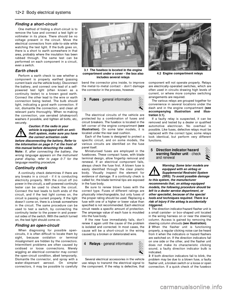
circuit breakers. The fusebox is located in the
left corner of the engine compartment (see
illustration). On some later models, it is
located under the rear seat cushion.
Each of the fuses is designed to protect a
specific circuit, and on some models, the
various circuits are identified on the fuse
panel itself.
Miniaturised fuses are employed in the
fuseboxes. These compact fuses, with blade
terminal design, allow fingertip removal and
renewal. If an electrical component fails,
always check the fuse first. A blown fuse is
easily identified through the clear plastic
body. Visually inspect the element for
evidence of damage. If a continuity check is
called for, the blade terminal tips are exposed
in the fuse body.
Be sure to renew blown fuses with the
correct type. Fuses of different ratings are
physically interchangeable, but only fuses of
the proper rating should be used. Replacing a
fuse with one of a higher or lower value than
specified is not recommended. Each electrical
circuit needs a specific amount of protection.
The amperage value of each fuse is moulded
into the fuse body.
If the new fuse immediately fails, don’t
renew it again until the cause of the problem
is isolated and corrected. In most cases, the
cause will be a short-circuit in the wiring
caused by a broken or deteriorated wire.
4 Relays- general information
1
Several electrical accessories in the vehicle
use relays to transmit the electrical signal to
the component. If the relay is defective, thatcomponent will not operate properly. Relays
are electrically-operated switches, which are
often used in circuits drawing high levels of
current, or where more complex switching
arrangements are required.
The various relays are grouped together for
convenience in several locations under the
dash and in the engine compartment (see
accompanying illustration and illus-
tration 3.1).
If a faulty relay is suspected, it can be
removed and tested by a dealer or qualified
automotive electrician. No overhaul is
possible. Like fuses, defective relays must be
replaced with the correct type; some relays
look identical, but perform very different
functions.
5 Direction indicator/hazard
warning flasher unit- check
and renewal
2
Warning: Some later models are
equipped with an airbag or
Supplemental Restraint System
(SRS). To avoid possible damage
to this system, the manufacturer
recommends that, on airbag-equipped
models, the following procedure should be
left to a dealer service department, or
other specialist, because of the special
tools and techniques required. There is a
risk of injury if the airbag is accidentally
triggered.
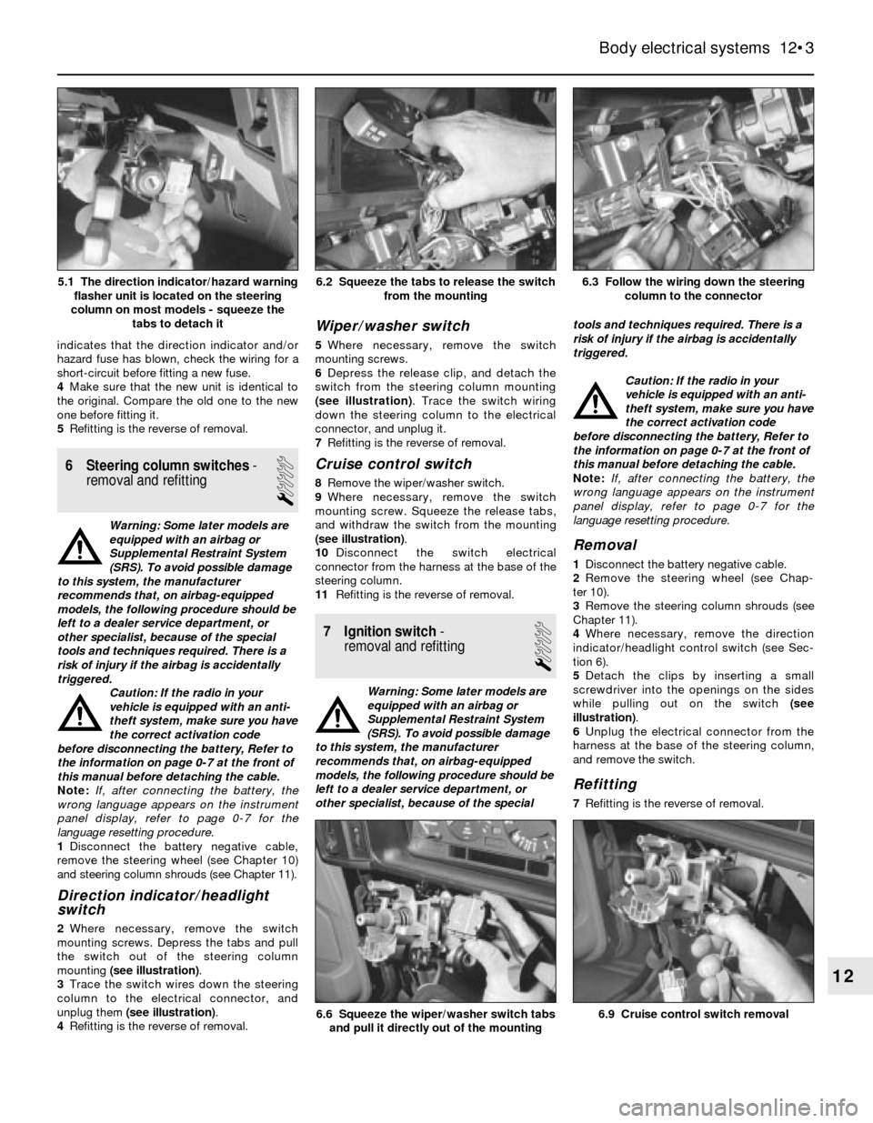
1The direction indicator/hazard flasher unit is
a small canister- or box-shaped unit located
in the wiring harness on or near the steering
column. Access is gained by removing the
steering column shrouds (see illustration).
2When the flasher unit is functioning
properly, a regular clicking noise can be heard
from it when the indicators or hazard flashers
are switched on. If the direction indicators fail
on one side or the other, and the flasher unit
does not make its characteristic clicking
sound, a faulty direction indicator bulb is
indicated.
3If both direction indicators fail to blink, the
problem may be due to a blown fuse, a faulty
flasher unit, a broken switch or a loose or open
connection. If a quick check of the fusebox
12•2 Body electrical systems
4.2 Engine compartment relays3.1 The fusebox is located in the engine
compartment under a cover - the box also
includes several relays
Page 171 of 228
indicates that the direction indicator and/or
hazard fuse has blown, check the wiring for a
short-circuit before fitting a new fuse.
4Make sure that the new unit is identical to
the original. Compare the old one to the new
one before fitting it.
5Refitting is the reverse of removal.
6 Steering column switches-
removal and refitting
1
Warning: Some later models are
equipped with an airbag or
Supplemental Restraint System
(SRS). To avoid possible damage
to this system, the manufacturer
recommends that, on airbag-equipped
models, the following procedure should be
left to a dealer service department, or
other specialist, because of the special
tools and techniques required. There is a
risk of injury if the airbag is accidentally
triggered.
Caution: If the radio in your
vehicle is equipped with an anti-
theft system, make sure you have
the correct activation code
before disconnecting the battery, Refer to
the information on page 0-7 at the front of
this manual before detaching the cable.
Note: If, after connecting the battery, the
wrong language appears on the instrument
panel display, refer to page 0-7 for the
language resetting procedure.
1Disconnect the battery negative cable,
remove the steering wheel (see Chapter 10)
and steering column shrouds (see Chapter 11).
Direction indicator/headlight
switch
2Where necessary, remove the switch
mounting screws. Depress the tabs and pull
the switch out of the steering column
mounting (see illustration).
3Trace the switch wires down the steering
column to the electrical connector, and
unplug them (see illustration).
4Refitting is the reverse of removal.
Wiper/washer switch
5Where necessary, remove the switch
mounting screws.
6Depress the release clip, and detach the
switch from the steering column mounting
(see illustration). Trace the switch wiring
down the steering column to the electrical
connector, and unplug it.
7Refitting is the reverse of removal.
Cruise control switch
8Remove the wiper/washer switch.
9Where necessary, remove the switch
mounting screw. Squeeze the release tabs,
and withdraw the switch from the mounting
(see illustration).
10Disconnect the switch electrical
connector from the harness at the base of the
steering column.
11Refitting is the reverse of removal.
7 Ignition switch-
removal and refitting
1
Warning: Some later models are
equipped with an airbag or
Supplemental Restraint System
(SRS). To avoid possible damage
to this system, the manufacturer
recommends that, on airbag-equipped
models, the following procedure should be
left to a dealer service department, or
other specialist, because of the specialtools and techniques required. There is a
risk of injury if the airbag is accidentally
triggered.
Caution: If the radio in your
vehicle is equipped with an anti-
theft system, make sure you have
the correct activation code
before disconnecting the battery, Refer to
the information on page 0-7 at the front of
this manual before detaching the cable.
Note: If, after connecting the battery, the
wrong language appears on the instrument
panel display, refer to page 0-7 for the
language resetting procedure.
Removal
1Disconnect the battery negative cable.
2Remove the steering wheel (see Chap-
ter 10).
3Remove the steering column shrouds (see
Chapter 11).
4Where necessary, remove the direction
indicator/headlight control switch (see Sec-
tion 6).
5Detach the clips by inserting a small
screwdriver into the openings on the sides
while pulling out on the switch (see
illustration).
6Unplug the electrical connector from the
harness at the base of the steering column,
and remove the switch.
Refitting
7Refitting is the reverse of removal.
Body electrical systems 12•3
6.3 Follow the wiring down the steering
column to the connector6.2 Squeeze the tabs to release the switch
from the mounting
6.9 Cruise control switch removal6.6 Squeeze the wiper/washer switch tabs
and pull it directly out of the mounting
12
5.1 The direction indicator/hazard warning
flasher unit is located on the steering
column on most models - squeeze the
tabs to detach it
Page 203 of 228
REF•2MOT Test Checks
Seat belts and seats
Note: The following checks are applicable to
all seat belts, front and rear.
MExamine the webbing of all the belts
(including rear belts if fitted) for cuts, serious
fraying or deterioration. Fasten and unfasten
each belt to check the buckles. If applicable,
check the retracting mechanism. Check the
security of all seat belt mountings accessible
from inside the vehicle.
MThe front seats themselves must be
securely attached and the backrests must
lock in the upright position.
Doors
MBoth front doors must be able to be opened
and closed from outside and inside, and must
latch securely when closed.
Vehicle identification
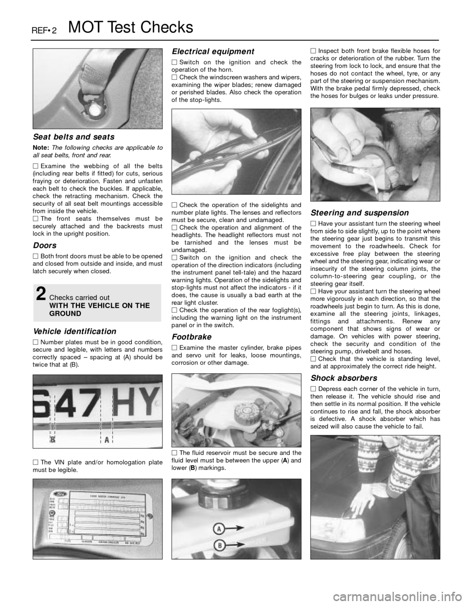
MNumber plates must be in good condition,
secure and legible, with letters and numbers
correctly spaced – spacing at (A) should be
twice that at (B).
MThe VIN plate and/or homologation plate
must be legible.
Electrical equipment
MSwitch on the ignition and check the
operation of the horn.
MCheck the windscreen washers and wipers,
examining the wiper blades; renew damaged
or perished blades. Also check the operation
of the stop-lights.
MCheck the operation of the sidelights and
number plate lights. The lenses and reflectors
must be secure, clean and undamaged.
MCheck the operation and alignment of the
headlights. The headlight reflectors must not
be tarnished and the lenses must be
undamaged.
MSwitch on the ignition and check the
operation of the direction indicators (including
the instrument panel tell-tale) and the hazard
warning lights. Operation of the sidelights and
stop-lights must not affect the indicators - if it
does, the cause is usually a bad earth at the
rear light cluster.
MCheck the operation of the rear foglight(s),
including the warning light on the instrument
panel or in the switch.
Footbrake
MExamine the master cylinder, brake pipes
and servo unit for leaks, loose mountings,
corrosion or other damage.
MThe fluid reservoir must be secure and the
fluid level must be between the upper (A) and
lower (B) markings.MInspect both front brake flexible hoses for
cracks or deterioration of the rubber. Turn the
steering from lock to lock, and ensure that the
hoses do not contact the wheel, tyre, or any
part of the steering or suspension mechanism.
With the brake pedal firmly depressed, check
the hoses for bulges or leaks under pressure.
Steering and suspension
MHave your assistant turn the steering wheel
from side to side slightly, up to the point where
the steering gear just begins to transmit this
movement to the roadwheels. Check for
excessive free play between the steering
wheel and the steering gear, indicating wear or
insecurity of the steering column joints, the
column-to-steering gear coupling, or the
steering gear itself.
MHave your assistant turn the steering wheel
more vigorously in each direction, so that the
roadwheels just begin to turn. As this is done,
examine all the steering joints, linkages,
fittings and attachments. Renew any
component that shows signs of wear or
damage. On vehicles with power steering,
check the security and condition of the
steering pump, drivebelt and hoses.
MCheck that the vehicle is standing level,
and at approximately the correct ride height.
Shock absorbers
MDepress each corner of the vehicle in turn,
then release it. The vehicle should rise and
then settle in its normal position. If the vehicle
continues to rise and fall, the shock absorber
is defective. A shock absorber which has
seized will also cause the vehicle to fail.
2Checks carried out
WITH THE VEHICLE ON THE
GROUND
Page 226 of 228

REF•26Index
E
Earth check - 12•2
Electric fan - 3•4
Electric shock - 0•5
Electric windows - 12•9
Electrical equipment - REF•2
Electrical system fault finding - 12•1
Electronic control system - 4•3, 4•14
Electronic control unit (ECU) - 6•1
Engine fault finding - REF•10
Engine tune-up - 1•7
Engine electrical systems- 5•1et seq
Engine electrical systems fault finding -
REF•11
Engine management and emission control
systems- 6•1et seq
Engine oil - 1•3, 1•7, 1•11
Environmental considerations - REF•8
Evaporative emissions control (EVAP)
system - 1•26, 6•5
Evaporator - 3•10
Exhaust emission checks - REF•4
Exhaust manifold - 2A•6
Exhaust system - 1•21, 4•20, REF•3
F
Fan - 3•4, 3•5
Fault finding- REF•9et seq
Fault finding - automatic transmission -
7B•2, REF•13
Fault finding - braking system - REF•14
Fault finding - clutch - REF•12
Fault finding - cooling system - REF•12
Fault finding - electrical system - 12•1,
REF•11
Fault finding - engine - REF•10
Fault finding - fuel system - 4•21, REF•12
Fault finding - manual transmission -
REF•13
Fault finding - suspension and steering -
REF•15
Filling - 11•3
Final drive - 8•2, 8•10, 8•11
Final drive oil - 1•3, 1•19, 1•26
Fire - 0•5
Flexible coupling - 8•7
Fluid level checks - 1•7
Fluid seals - 7B•5
Flywheel - 2A•18
Fuel and exhaust systems- 1•20, 4•1et
seq,REF•4
Fuel system fault finding - REF•12
Fuel filter - 1•25
Fuel hoses - 1•14
Fuel injection system - 4•3, 4•14
Fuel injection system - fault finding - 4•21
Fuel injectors - 4•18
Fuel level sender unit - 4•5, 4•6
Fuel lines and fittings - 4•7
Fuel pressure - 4•3
Fuel pressure regulator - 4•16
Fuel pump - 4•3, 4•4, 4•5
Fuel tank - 4•7, 4•8
Fume or gas intoxication - 0•5
Fuses - 12•2
G
Gaiters - 1•22, 8•9, 10•13
Gashes in bodywork - 11•2
Gaskets - REF•8
Gear lever - 7A•1
Gearbox - SeeManual transmission
Gearbox oil - 1•3, 1•19, 1•25
General engine overhaul procedures-
2B•1et seq
Glass - 11•4, 11•8
Glossary of technical terms - REF•20
Grille - 11•4
H
Handbrake - 1•23, 9•2, 9•12, REF•1
Handbrake fault - REF•14
Handles - 11•8
Hazard warning flasher - 12•2
HC emissions - REF•4
Headlights - 12•3, 12•5, 12•6
Heated rear window - 12•8
Heater - 3•2, 3•7, 3•8
Hinges - 11•4
HT leads - 1•18
Hubs - 10•8, 10•11, REF•3
Hydraulic servo - 9•11
Hydraulic tappets - 2B•11
Hydrofluoric acid - 0•5
I
Idle air stabiliser valve - 4•18
Idle speed adjustment - 1•15
Ignition coil - 5•5
Ignition control unit - 5•6, 5•7
Ignition sensors - 5•8
Ignition switch - 12•3
Ignition system - 5•3
Ignition timing - 5•4
Ignition timing sensors - 6•4
Impulse generator - 5•6, 5•7
In-car engine repair procedures- 2A•1et
seq
Indicators - 12•2, 12•3
Information sensors - 6•2
Injectors - 4•18
Input shaft - 7A•2
Instrument cluster - 12•4
Instrument panel language display - 0•7
Intake manifold - 2A•4
Intermediate shaft - 2A•12, 2B•14, 2B•19
Introduction to the BMW 3- and 5-Series -
0•4
J
Jacking - 0•8
Joint mating faces - REF•8
Jump starting - 0•9
K
Kickdown cable - 7B•3
L
L-Jetronic fuel injection system - 4•14,
4•19
Language display - 0•7
Latch - 11•8
Leaks - 0•10, 7B•3, REF•12, REF•13
Locknuts, locktabs and washers - REF•8
Locks - 11•4, 11•8
Lubricants - REF•18
M
Main bearings - 2B•17, 2B•19
Manifolds - 2A•4, 2A•6
Manual transmission- 7A•1et seq
Manual transmission fault finding - REF•13
Manual transmission oil - 1•3, 1•19, 1•25
Master cylinder - 8•3, 9•9
Mechanical fan - 3•4, 3•5
Mirrors - 11•8, REF•1
Misfire - REF•11
Mixture - REF•4
MOT test checks- REF•1 et seq
Motronic engine management system -
6•1
Motronic fuel injection system - 4•14, 4•19
Mountings - 2A•19, 7A•3
O
Oil - differential - 1•19, 1•26
Oil - engine - 1•3, 1•7, 1•11
Oil - final drive - 1•3
Oil - manual transmission - 1•3, 1•19, 1•25
Oil filter - 1•11, 1•12
Oil pump - 2A•16
Oil seals - 2A•12, 2A•13, 2A•19, 2B•20,
7A•2, 7B•5, 8•10, 8•12, REF•8
Open-circuit - 12•2
Output shaft - 7A•2, 7B•5
Overcooling - REF•12
Overheating - REF•12
Oxygen sensor - 6•2
P
Pads - 9•2, 9•3
Pedals - 8•3, 9•13
Pinion oil - 8•12
Pinking - REF•11
Piston rings - 2B•18
Pistons - 2B•12, 2B•16, 2B•21
Plastic components - 11•3
Poisonous or irritant substances - 0•5
Position sensors - 5•8
Positive crankcase ventilation (PCV)
system - 6•4
Power steering - 1•14, 10•15, 10•16
Power steering fluid - 1•12
Propeller shaft - 8•2, 8•6, 8•8
Pulse sensor - 5•8
Purge valve - 6•5