pressure BMW 3 SERIES 1990 E30 Workshop Manual
[x] Cancel search | Manufacturer: BMW, Model Year: 1990, Model line: 3 SERIES, Model: BMW 3 SERIES 1990 E30Pages: 228, PDF Size: 7.04 MB
Page 6 of 228
0•6Safety First!
Working on your car can be dangerous.
This page shows just some of the potential
risks and hazards, with the aim of creating a
safety-conscious attitude.
General hazards
Scalding
• Don’t remove the radiator or expansion
tank cap while the engine is hot.
• Engine oil, automatic transmission fluid or
power steering fluid may also be dangerously
hot if the engine has recently been running.
Burning
• Beware of burns from the exhaust system
and from any part of the engine. Brake discs
and drums can also be extremely hot
immediately after use.
Crushing
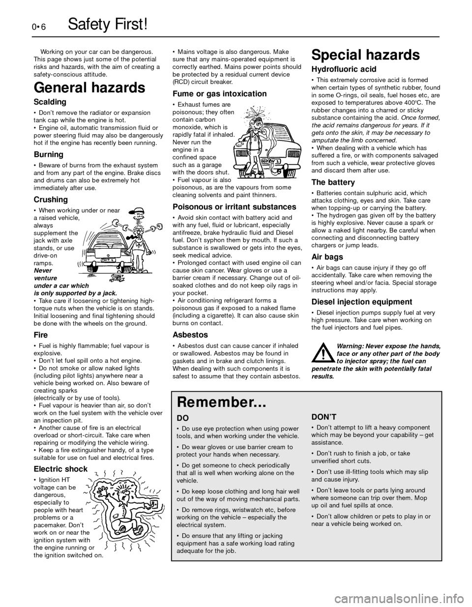
• When working under or near
a raised vehicle,
always
supplement the
jack with axle
stands, or use
drive-on
ramps.
Never
venture
under a car which
is only supported by a jack.
• Take care if loosening or tightening high-
torque nuts when the vehicle is on stands.
Initial loosening and final tightening should
be done with the wheels on the ground.
Fire
• Fuel is highly flammable; fuel vapour is
explosive.
• Don’t let fuel spill onto a hot engine.
• Do not smoke or allow naked lights
(including pilot lights) anywhere near a
vehicle being worked on. Also beware of
creating sparks
(electrically or by use of tools).
• Fuel vapour is heavier than air, so don’t
work on the fuel system with the vehicle over
an inspection pit.
• Another cause of fire is an electrical
overload or short-circuit. Take care when
repairing or modifying the vehicle wiring.
• Keep a fire extinguisher handy, of a type
suitable for use on fuel and electrical fires.
Electric shock
• Ignition HT
voltage can be
dangerous,
especially to
people with heart
problems or a
pacemaker. Don’t
work on or near the
ignition system with
the engine running or
the ignition switched on.• Mains voltage is also dangerous. Make
sure that any mains-operated equipment is
correctly earthed. Mains power points should
be protected by a residual current device
(RCD) circuit breaker.
Fume or gas intoxication
• Exhaust fumes are
poisonous; they often
contain carbon
monoxide, which is
rapidly fatal if inhaled.
Never run the
engine in a
confined space
such as a garage
with the doors shut.
• Fuel vapour is also
poisonous, as are the vapours from some
cleaning solvents and paint thinners.
Poisonous or irritant substances
• Avoid skin contact with battery acid and
with any fuel, fluid or lubricant, especially
antifreeze, brake hydraulic fluid and Diesel
fuel. Don’t syphon them by mouth. If such a
substance is swallowed or gets into the eyes,
seek medical advice.
• Prolonged contact with used engine oil can
cause skin cancer. Wear gloves or use a
barrier cream if necessary. Change out of oil-
soaked clothes and do not keep oily rags in
your pocket.
• Air conditioning refrigerant forms a
poisonous gas if exposed to a naked flame
(including a cigarette). It can also cause skin
burns on contact.
Asbestos
• Asbestos dust can cause cancer if inhaled
or swallowed. Asbestos may be found in
gaskets and in brake and clutch linings.
When dealing with such components it is
safest to assume that they contain asbestos.
Special hazards
Hydrofluoric acid
• This extremely corrosive acid is formed
when certain types of synthetic rubber, found
in some O-rings, oil seals, fuel hoses etc, are
exposed to temperatures above 400
0C. The
rubber changes into a charred or sticky
substance containing the acid. Once formed,
the acid remains dangerous for years. If it
gets onto the skin, it may be necessary to
amputate the limb concerned.
• When dealing with a vehicle which has
suffered a fire, or with components salvaged
from such a vehicle, wear protective gloves
and discard them after use.
The battery
• Batteries contain sulphuric acid, which
attacks clothing, eyes and skin. Take care
when topping-up or carrying the battery.
• The hydrogen gas given off by the battery
is highly explosive. Never cause a spark or
allow a naked light nearby. Be careful when
connecting and disconnecting battery
chargers or jump leads.
Air bags
• Air bags can cause injury if they go off
accidentally. Take care when removing the
steering wheel and/or facia. Special storage
instructions may apply.
Diesel injection equipment
• Diesel injection pumps supply fuel at very
high pressure. Take care when working on
the fuel injectors and fuel pipes.
Warning: Never expose the hands,
face or any other part of the body
to injector spray; the fuel can
penetrate the skin with potentially fatal
results.
Remember...
DO
• Do use eye protection when using power
tools, and when working under the vehicle.
• Do wear gloves or use barrier cream to
protect your hands when necessary.
• Do get someone to check periodically
that all is well when working alone on the
vehicle.
• Do keep loose clothing and long hair well
out of the way of moving mechanical parts.
• Do remove rings, wristwatch etc, before
working on the vehicle – especially the
electrical system.
• Do ensure that any lifting or jacking
equipment has a safe working load rating
adequate for the job.
A few tips
DON’T
• Don’t attempt to lift a heavy component
which may be beyond your capability – get
assistance.
• Don’t rush to finish a job, or take
unverified short cuts.
• Don’t use ill-fitting tools which may slip
and cause injury.
• Don’t leave tools or parts lying around
where someone can trip over them. Mop
up oil and fuel spills at once.
• Don’t allow children or pets to play in or
near a vehicle being worked on.
Page 11 of 228

1
Engine
Oil filter
M10 engines . . . . . . . . . . . . . . . . . . . . . . . . . . . . . . . . . . . . . . . . . . . . Champion C121
M20 engines . . . . . . . . . . . . . . . . . . . . . . . . . . . . . . . . . . . . . . . . . . . . Champion C160
M30 engines
3-Series . . . . . . . . . . . . . . . . . . . . . . . . . . . . . . . . . . . . . . . . . . . . . . Champion C160
5-Series . . . . . . . . . . . . . . . . . . . . . . . . . . . . . . . . . . . . . . . . . . . . . . Champion X115
M40 engines . . . . . . . . . . . . . . . . . . . . . . . . . . . . . . . . . . . . . . . . . . . . Champion X120
Valve clearances (intake and exhaust)
M10 engines
Cold . . . . . . . . . . . . . . . . . . . . . . . . . . . . . . . . . . . . . . . . . . . . . . . . . 0.20 mm
Hot . . . . . . . . . . . . . . . . . . . . . . . . . . . . . . . . . . . . . . . . . . . . . . . . . 0.25 mm
M20 engines
Cold . . . . . . . . . . . . . . . . . . . . . . . . . . . . . . . . . . . . . . . . . . . . . . . . . 0.25 mm
Hot . . . . . . . . . . . . . . . . . . . . . . . . . . . . . . . . . . . . . . . . . . . . . . . . . 0.30 mm
M30 engines
Cold . . . . . . . . . . . . . . . . . . . . . . . . . . . . . . . . . . . . . . . . . . . . . . . . . 0.30 mm
Hot . . . . . . . . . . . . . . . . . . . . . . . . . . . . . . . . . . . . . . . . . . . . . . . . . 0.35 mm
M40 engines . . . . . . . . . . . . . . . . . . . . . . . . . . . . . . . . . . . . . . . . . . . . Hydraulic adjusters
Cooling system
Antifreeze mixture . . . . . . . . . . . . . . . . . . . . . . . . . . . . . . . . . . . . . . . . . . 40% antifreeze/60% water
Chapter 1
Routine maintenance and servicing
Air filter renewal . . . . . . . . . . . . . . . . . . . . . . . . . . . . . . . . . . . . . . . . . 20
Automatic transmission fluid and filter change . . . . . . . . . . . . . . . . . 28
Automatic transmission fluid level check . . . . . . . . . . . . . . . . . . . . . 8
Battery check, maintenance and charging . . . . . . . . . . . . . . . . . . . . 13
Brake system check . . . . . . . . . . . . . . . . . . . . . . . . . . . . . . . . . . . . . 26
Cooling system - draining, flushing and refilling . . . . . . . . . . . . . . . . 29
Cooling system check . . . . . . . . . . . . . . . . . . . . . . . . . . . . . . . . . . . . 22
Differential lubricant change . . . . . . . . . . . . . . . . . . . . . . . . . . . . . . . 32
Differential lubricant level check . . . . . . . . . . . . . . . . . . . . . . . . . . . . 17
Driveshaft gaiter check . . . . . . . . . . . . . . . . . . . . . . . . . . . . . . . . . . . 25
Drivebelt check, adjustment and renewal . . . . . . . . . . . . . . . . . . . . . 11
Engine idle speed and CO level check and adjustment . . . . . . . . . . 12
Engine oil and filter change . . . . . . . . . . . . . . . . . . . . . . . . . . . . . . . . 6
Engine timing belt renewal . . . . . . . . . . . . . . . . . . . . . . . . . . . . . . . . 35
Exhaust system check . . . . . . . . . . . . . . . . . . . . . . . . . . . . . . . . . . . 23
Evaporative Emissions Control (EVAP) system check . . . . . . . . . . . 33
Fluid level checks . . . . . . . . . . . . . . . . . . . . . . . . . . . . . . . . . . . . . . . 4
Fuel filter renewal . . . . . . . . . . . . . . . . . . . . . . . . . . . . . . . . . . . . . . . 30 Fuel system check . . . . . . . . . . . . . . . . . . . . . . . . . . . . . . . . . . . . . . 21
Introduction . . . . . . . . . . . . . . . . . . . . . . . . . . . . . . . . . . . . . . . . . . . . 1
Manual transmission lubricant change . . . . . . . . . . . . . . . . . . . . . . . 31
Manual transmission lubricant level check . . . . . . . . . . . . . . . . . . . . 16
Power steering fluid level check . . . . . . . . . . . . . . . . . . . . . . . . . . . . 7
Routine maintenance . . . . . . . . . . . . . . . . . . . . . . . . . . . . . . . . . . . . 2
Service light resetting . . . . . . . . . . . . . . . . . . . . . . . . . . . . . . . . . . . . 34
Spark plug check and renewal . . . . . . . . . . . . . . . . . . . . . . . . . . . . . 14
Spark plug HT leads, distributor cap and rotor - check
and renewal . . . . . . . . . . . . . . . . . . . . . . . . . . . . . . . . . . . . . . . . . . 15
Steering and suspension check . . . . . . . . . . . . . . . . . . . . . . . . . . . . 24
Throttle linkage - check and lubrication . . . . . . . . . . . . . . . . . . . . . . 19
Tyre and tyre pressure checks . . . . . . . . . . . . . . . . . . . . . . . . . . . . . 5
Tyre rotation . . . . . . . . . . . . . . . . . . . . . . . . . . . . . . . . . . . . . . . . . . . 9
Tune-up general information . . . . . . . . . . . . . . . . . . . . . . . . . . . . . . . 3
Underbonnet hoses - check and renewal . . . . . . . . . . . . . . . . . . . . . 10
Valve clearances - check and adjustment . . . . . . . . . . . . . . . . . . . . 18
Wiper blades - check and renewal . . . . . . . . . . . . . . . . . . . . . . . . . . 27
1•1
Easy,suitable for
novice with little
experienceFairly easy,suitable
for beginner with
some experienceFairly difficult,
suitable for competent
DIY mechanic
Difficult,suitable for
experienced DIY
mechanicVery difficult,
suitable for expert
DIY or professional
Degrees of difficulty
Specifications Contents
Page 13 of 228

Tyre pressures (cold) - bars (psi)Front Rear
3-Series, E30
316 . . . . . . . . . . . . . . . . . . . . . . . . . . . . . . . . . . . . . . . . . . . . . . . . . . . 1.9 (28) 2.1 (30)
316i
Saloon . . . . . . . . . . . . . . . . . . . . . . . . . . . . . . . . . . . . . . . . . . . . . . . 2.0 (29) 2.1 (30)
Estate . . . . . . . . . . . . . . . . . . . . . . . . . . . . . . . . . . . . . . . . . . . . . . . 2.0 (29) 2.2 (32)
318i . . . . . . . . . . . . . . . . . . . . . . . . . . . . . . . . . . . . . . . . . . . . . . . . . . . 1.8 (26) 1.9 (28)
320i . . . . . . . . . . . . . . . . . . . . . . . . . . . . . . . . . . . . . . . . . . . . . . . . . . . 1.9 (28) 2.0 (29)
325i . . . . . . . . . . . . . . . . . . . . . . . . . . . . . . . . . . . . . . . . . . . . . . . . . . . 2.2 (32) 2.3 (33)
5-Series, E28 (“old-shape”)
518 and 518i . . . . . . . . . . . . . . . . . . . . . . . . . . . . . . . . . . . . . . . . . . . . 2.0 (29) 2.0 (29)
525i and 528i . . . . . . . . . . . . . . . . . . . . . . . . . . . . . . . . . . . . . . . . . . . 2.2 (32) 2.2 (32)
535i and M535i . . . . . . . . . . . . . . . . . . . . . . . . . . . . . . . . . . . . . . . . . . 2.3 (33) 2.5 (36)
5-Series, E34 (“new-shape”)
518i . . . . . . . . . . . . . . . . . . . . . . . . . . . . . . . . . . . . . . . . . . . . . . . . . . . 2.0 (29) 2.0 (29)
520i . . . . . . . . . . . . . . . . . . . . . . . . . . . . . . . . . . . . . . . . . . . . . . . . . . . 2.2 (32) 2.1 (30)
525i, 530i and 535i . . . . . . . . . . . . . . . . . . . . . . . . . . . . . . . . . . . . . . . 2.0 (29) 2.3 (33)
Torque wrench settingsNm
Automatic transmission sump bolts
Three-speed . . . . . . . . . . . . . . . . . . . . . . . . . . . . . . . . . . . . . . . . . . . . 8 to 9
Four-speed . . . . . . . . . . . . . . . . . . . . . . . . . . . . . . . . . . . . . . . . . . . . . 5 to 7
Spark plugs
M10 engines . . . . . . . . . . . . . . . . . . . . . . . . . . . . . . . . . . . . . . . . . . . . 20 to 30
Except M10 engines . . . . . . . . . . . . . . . . . . . . . . . . . . . . . . . . . . . . . . 30 to 33
Oxygen sensor . . . . . . . . . . . . . . . . . . . . . . . . . . . . . . . . . . . . . . . . . . . . 30 to 33
Wheel bolts . . . . . . . . . . . . . . . . . . . . . . . . . . . . . . . . . . . . . . . . . . . . . . . 100
Lubricants and fluids
Component or system Lubricant type/specification
Engine . . . . . . . . . . . . . . . . . . . . . . . . . . . . . . . . . . . . . . . . . . . . . . . . . . Multigrade engine oil, viscositySAE 10W/40 to 20W/50, to API SG
Cooling system . . . . . . . . . . . . . . . . . . . . . . . . . . . . . . . . . . . . . . . . . . . Ethylene glycol-based antifreeze with corrosion inhibitors
Manual transmission* . . . . . . . . . . . . . . . . . . . . . . . . . . . . . . . . . . . . . . Gear oil, viscosity SAE 80 to API-GL4, or single-grade mineral-based
engine oil, viscosity SAE 20, 30 or 40 to API-SG
Automatic transmission . . . . . . . . . . . . . . . . . . . . . . . . . . . . . . . . . . . . Dexron ll type ATF
Final drive . . . . . . . . . . . . . . . . . . . . . . . . . . . . . . . . . . . . . . . . . . . . . . . BMW-approved hypoid gear oil, viscosity SAE 90**
Brake and clutch hydraulic systems . . . . . . . . . . . . . . . . . . . . . . . . . . Hydraulic brake fluid to SAE J 1703 or DOT 4
Power steering . . . . . . . . . . . . . . . . . . . . . . . . . . . . . . . . . . . . . . . . . . . Dexron ll type ATF
* E34 520i & 525i with air conditioning, E34 530i & 535i - Dexron II type ATF)
** Only available in bulk; refer to your BMW dealer
Capacities*
1•3
1
Engine oil
M10 engines . . . . . . . . . . . . . . . . . . . . . . . . . . . . . . 4.0 litres
M20 engines . . . . . . . . . . . . . . . . . . . . . . . . . . . . . . 4.3 litres
M30 engines . . . . . . . . . . . . . . . . . . . . . . . . . . . . . . 5.8 litres
M40 engines . . . . . . . . . . . . . . . . . . . . . . . . . . . . . . 4.0 litres
Cooling system
M10 engines . . . . . . . . . . . . . . . . . . . . . . . . . . . . . . 7.0 litres
M20 engines . . . . . . . . . . . . . . . . . . . . . . . . . . . . . . 10.5 litres
M30 engines . . . . . . . . . . . . . . . . . . . . . . . . . . . . . . 12.0 litres
M40 engines . . . . . . . . . . . . . . . . . . . . . . . . . . . . . . 7.0 litres
Fuel tank
3-Series, E30
Saloon . . . . . . . . . . . . . . . . . . . . . . . . . . . . . . . . 55 litres (early),
64 litres (later)
Estate . . . . . . . . . . . . . . . . . . . . . . . . . . . . . . . . . 63 litres (early),
70 litres (later)
5-Series
E28 (“old-shape”) . . . . . . . . . . . . . . . . . . . . . . . . 70 litres
E34 (“new-shape”) . . . . . . . . . . . . . . . . . . . . . . . 81 litresManual transmission
ZF . . . . . . . . . . . . . . . . . . . . . . . . . . . . . . . . . . . . . . 1.2 litres
Getrag . . . . . . . . . . . . . . . . . . . . . . . . . . . . . . . . . . 1.0 to 1.5 litres
Automatic transmission (refill)
3-speed . . . . . . . . . . . . . . . . . . . . . . . . . . . . . . . . . 2.0 litres
4-speed . . . . . . . . . . . . . . . . . . . . . . . . . . . . . . . . . 3.0 litres
Final drive capacity (drain and refill)
3-Series, E30 . . . . . . . . . . . . . . . . . . . . . . . . . . . . . 0.9 litres
5-Series, E28 (“old-shape”) . . . . . . . . . . . . . . . . . . 0.9 litres
5-Series, E34 (“new-shape”) . . . . . . . . . . . . . . . . . 1.7 litres
*All capacities approximate
Servicing Specifications
Page 14 of 228
Maintenance schedule
The following maintenance intervals are based on the assumption
that the vehicle owner will be doing the maintenance or service work,
as opposed to having a dealer service department do the work.
Although the time/mileage intervals are loosely based on factory rec-
ommendations, most have been shortened to ensure, for example, that
such items as lubricants and fluids are checked/changed at intervals
that promote maximum engine/driveline service life. Also, subject to
the preference of the individual owner interested in keeping his or her
vehicle in peak condition at all times, and with the vehicle’s ultimate
resale in mind, many of the maintenance procedures may be
performed more often than recommended in the following schedule.
We encourage such owner initiative.
When the vehicle is new, it should be serviced initially by a factory-
authorised dealer service department, to protect the factory warranty.
In many cases, the initial maintenance check is done at no cost to the
owner (check with your dealer service department for more
information).
1•4Maintenance and servicing
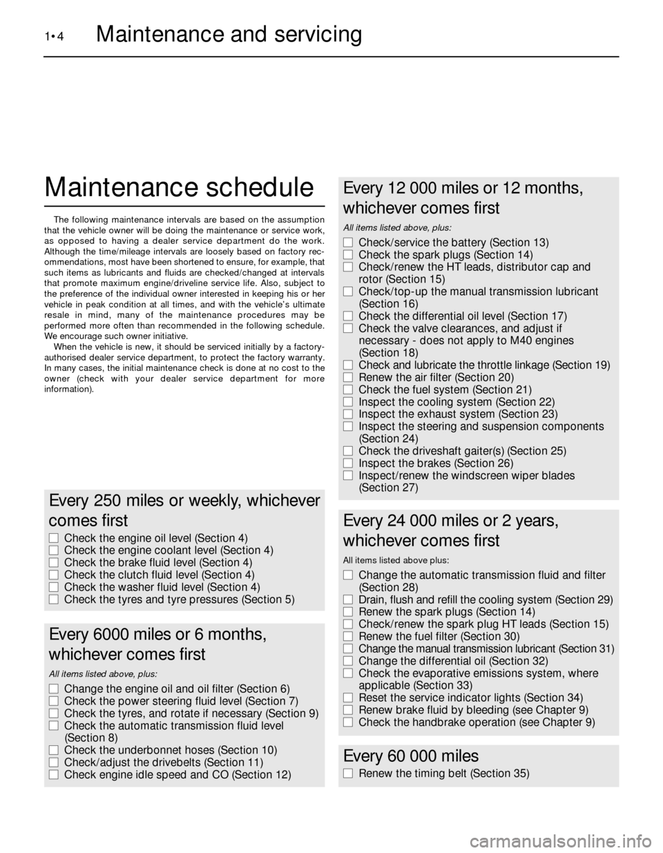
Every 250 miles or weekly, whichever
comes first
m mCheck the engine oil level (Section 4)
m mCheck the engine coolant level (Section 4)
m mCheck the brake fluid level (Section 4)
m mCheck the clutch fluid level (Section 4)
m mCheck the washer fluid level (Section 4)
m mCheck the tyres and tyre pressures (Section 5)
Every 6000 miles or 6 months,
whichever comes first
All items listed above, plus:
m mChange the engine oil and oil filter (Section 6)
m mCheck the power steering fluid level (Section 7)
m mCheck the tyres, and rotate if necessary (Section 9)
m mCheck the automatic transmission fluid level
(Section 8)
m mCheck the underbonnet hoses (Section 10)
m mCheck/adjust the drivebelts (Section 11)
m mCheck engine idle speed and CO (Section 12)
Every 12 000 miles or 12 months,
whichever comes first
All items listed above, plus:
m mCheck/service the battery (Section 13)
m mCheck the spark plugs (Section 14)
m mCheck/renew the HT leads, distributor cap and
rotor (Section 15)
m mCheck/top-up the manual transmission lubricant
(Section 16)
m mCheck the differential oil level (Section 17)
m mCheck the valve clearances, and adjust if
necessary - does not apply to M40 engines
(Section 18)
m mCheck and lubricate the throttle linkage (Section 19)
m mRenew the air filter (Section 20)
m mCheck the fuel system (Section 21)
m mInspect the cooling system (Section 22)
m mInspect the exhaust system (Section 23)
m mInspect the steering and suspension components
(Section 24)
m mCheck the driveshaft gaiter(s) (Section 25)
m mInspect the brakes (Section 26)
m mInspect/renew the windscreen wiper blades
(Section 27)
Every 24 000 miles or 2 years,
whichever comes first
All items listed above plus:
m mChange the automatic transmission fluid and filter
(Section 28)
m mDrain, flush and refill the cooling system (Section 29)
m mRenew the spark plugs (Section 14)
m mCheck/renew the spark plug HT leads (Section 15)
m mRenew the fuel filter (Section 30)
m mChange the manual transmission lubricant (Section 31)
m mChange the differential oil (Section 32)
m mCheck the evaporative emissions system, where
applicable (Section 33)
m mReset the service indicator lights (Section 34)
m mRenew brake fluid by bleeding (see Chapter 9)
m mCheck the handbrake operation (see Chapter 9)
Every 60 000 miles
m
mRenew the timing belt (Section 35)
Page 18 of 228
engine damage. Conversely, overfilling the
engine (adding oil above the upper mark) may
cause oil-fouled spark plugs, oil leaks, or oil
seal failures.
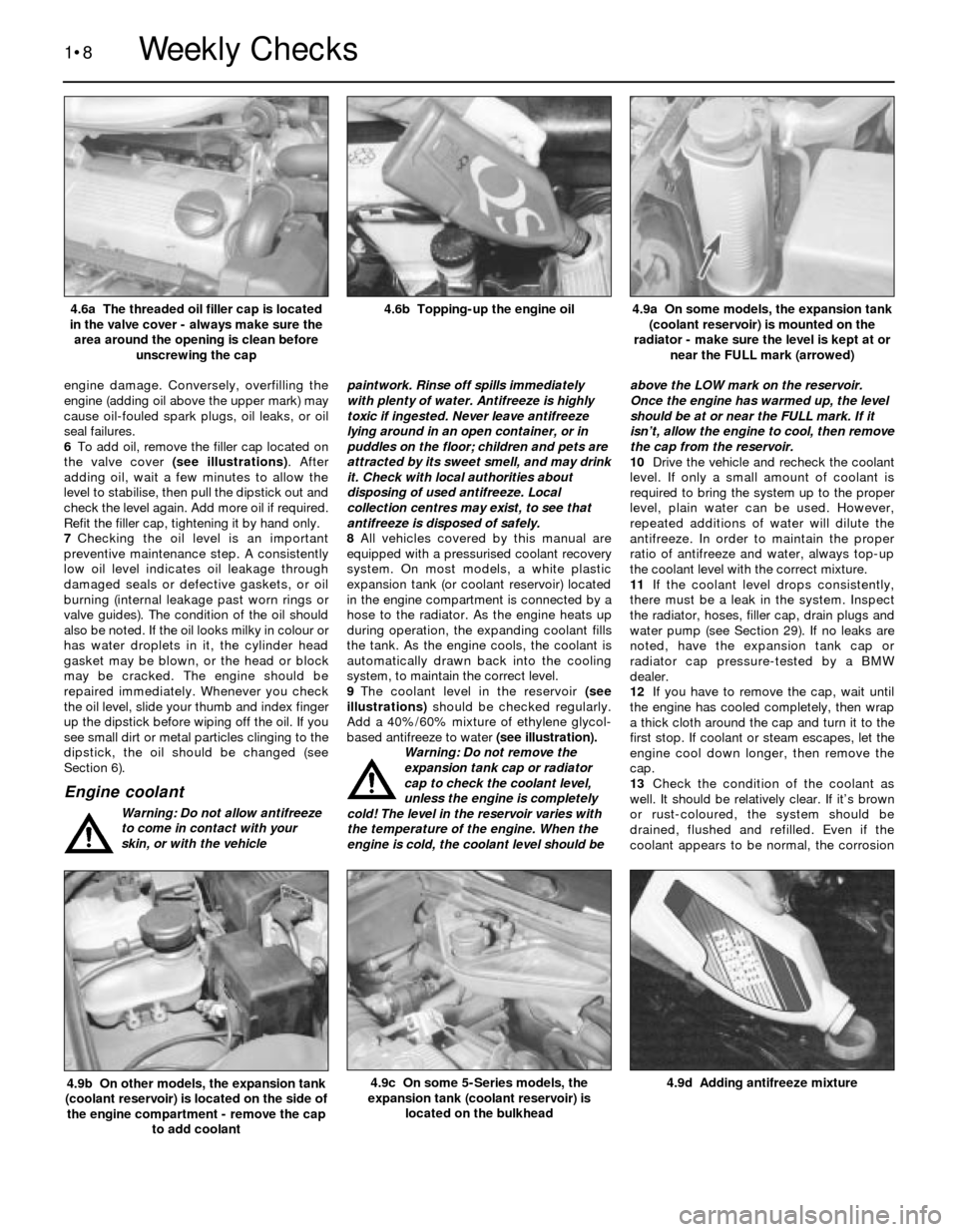
6To add oil, remove the filler cap located on
the valve cover (see illustrations). After
adding oil, wait a few minutes to allow the
level to stabilise, then pull the dipstick out and
check the level again. Add more oil if required.
Refit the filler cap, tightening it by hand only.
7Checking the oil level is an important
preventive maintenance step. A consistently
low oil level indicates oil leakage through
damaged seals or defective gaskets, or oil
burning (internal leakage past worn rings or
valve guides). The condition of the oil should
also be noted. If the oil looks milky in colour or
has water droplets in it, the cylinder head
gasket may be blown, or the head or block
may be cracked. The engine should be
repaired immediately. Whenever you check
the oil level, slide your thumb and index finger
up the dipstick before wiping off the oil. If you
see small dirt or metal particles clinging to the
dipstick, the oil should be changed (see
Section 6).
Engine coolant
Warning: Do not allow antifreeze
to come in contact with your
skin, or with the vehiclepaintwork. Rinse off spills immediately
with plenty of water. Antifreeze is highly
toxic if ingested. Never leave antifreeze
lying around in an open container, or in
puddles on the floor; children and pets are
attracted by its sweet smell, and may drink
it. Check with local authorities about
disposing of used antifreeze. Local
collection centres may exist, to see that
antifreeze is disposed of safely.
8All vehicles covered by this manual are
equipped with a pressurised coolant recovery
system. On most models, a white plastic
expansion tank (or coolant reservoir) located
in the engine compartment is connected by a
hose to the radiator. As the engine heats up
during operation, the expanding coolant fills
the tank. As the engine cools, the coolant is
automatically drawn back into the cooling
system, to maintain the correct level.
9The coolant level in the reservoir (see
illustrations)should be checked regularly.
Add a 40%/60% mixture of ethylene glycol-
based antifreeze to water (see illustration).
Warning: Do not remove the
expansion tank cap or radiator
cap to check the coolant level,
unless the engine is completely
cold! The level in the reservoir varies with
the temperature of the engine. When the
engine is cold, the coolant level should beabove the LOW mark on the reservoir.
Once the engine has warmed up, the level
should be at or near the FULL mark. If it
isn’t, allow the engine to cool, then remove
the cap from the reservoir.
10Drive the vehicle and recheck the coolant
level. If only a small amount of coolant is
required to bring the system up to the proper
level, plain water can be used. However,
repeated additions of water will dilute the
antifreeze. In order to maintain the proper
ratio of antifreeze and water, always top-up
the coolant level with the correct mixture.
11If the coolant level drops consistently,
there must be a leak in the system. Inspect
the radiator, hoses, filler cap, drain plugs and
water pump (see Section 29). If no leaks are
noted, have the expansion tank cap or
radiator cap pressure-tested by a BMW
dealer.
12If you have to remove the cap, wait until
the engine has cooled completely, then wrap
a thick cloth around the cap and turn it to the
first stop. If coolant or steam escapes, let the
engine cool down longer, then remove the
cap.
13Check the condition of the coolant as
well. It should be relatively clear. If it’s brown
or rust-coloured, the system should be
drained, flushed and refilled. Even if the
coolant appears to be normal, the corrosion
1•8
4.9d Adding antifreeze mixture4.9c On some 5-Series models, the
expansion tank (coolant reservoir) is
located on the bulkhead4.9b On other models, the expansion tank
(coolant reservoir) is located on the side of
the engine compartment - remove the cap
to add coolant
4.9a On some models, the expansion tank
(coolant reservoir) is mounted on the
radiator - make sure the level is kept at or
near the FULL mark (arrowed)4.6b Topping-up the engine oil4.6a The threaded oil filler cap is located
in the valve cover - always make sure the
area around the opening is clean before
unscrewing the cap
Weekly Checks
Page 19 of 228
inhibitors wear out, so it must be renewed at
the specified intervals.
Brake and clutch fluid
Warning: Brake fluid can harm
your eyes and damage painted
surfaces, so use extreme caution
when handling or pouring it. Do
not use brake fluid that has been standing
open or is more than one year old. Brake
fluid absorbs moisture from the air, which
can cause a dangerous loss of brake
effectiveness. Use only the specified type
of brake fluid. Mixing different types (such
as DOT 3 or 4 and DOT 5) can cause brake
failure.
14The brake master cylinder is mounted at
the left rear corner of the engine
compartment. The clutch fluid reservoir
(manual transmission models) is mounted on
the right-hand side.
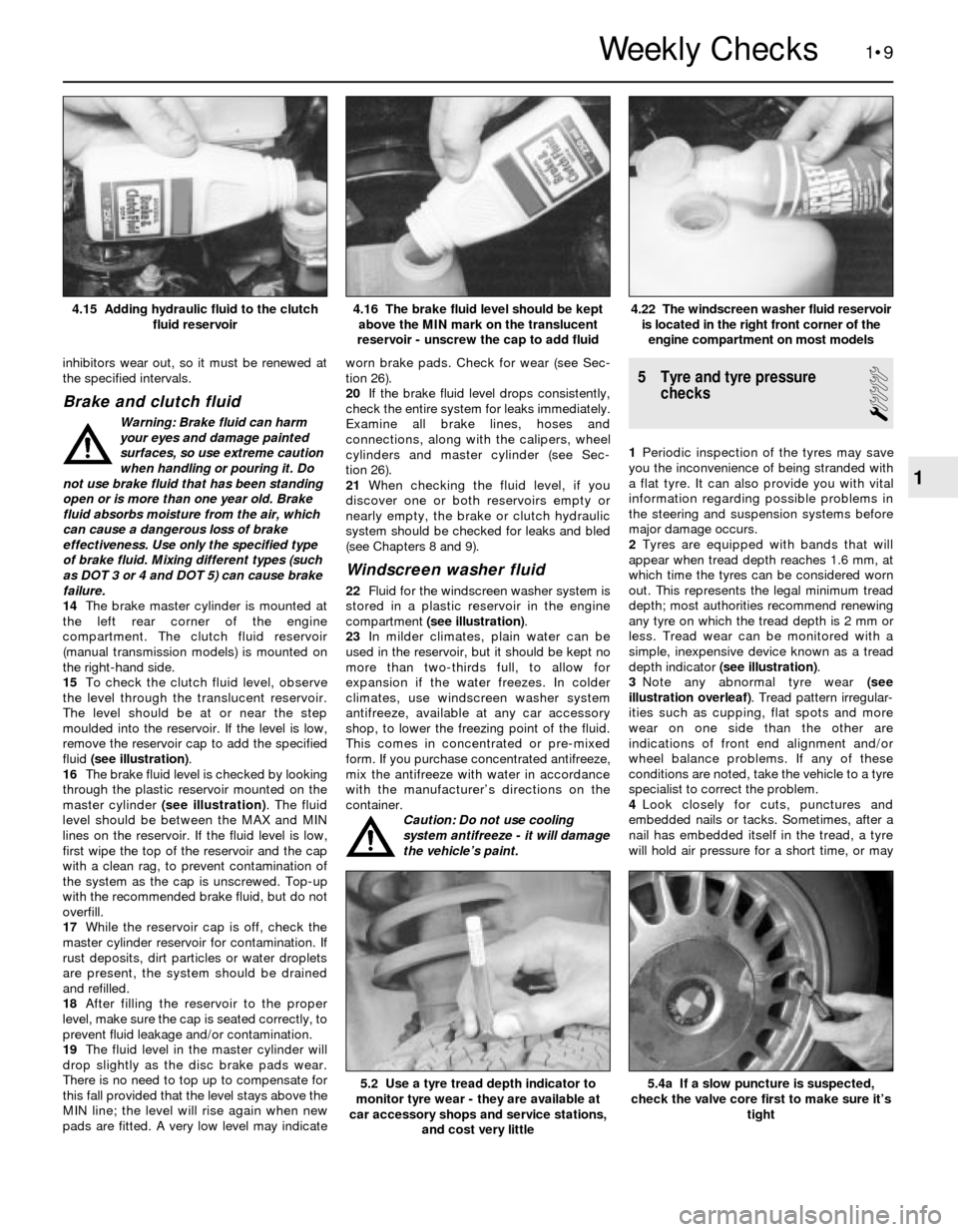
15To check the clutch fluid level, observe
the level through the translucent reservoir.
The level should be at or near the step
moulded into the reservoir. If the level is low,
remove the reservoir cap to add the specified
fluid (see illustration).
16The brake fluid level is checked by looking
through the plastic reservoir mounted on the
master cylinder (see illustration). The fluid
level should be between the MAX and MIN
lines on the reservoir. If the fluid level is low,
first wipe the top of the reservoir and the cap
with a clean rag, to prevent contamination of
the system as the cap is unscrewed. Top-up
with the recommended brake fluid, but do not
overfill.
17While the reservoir cap is off, check the
master cylinder reservoir for contamination. If
rust deposits, dirt particles or water droplets
are present, the system should be drained
and refilled.
18After filling the reservoir to the proper
level, make sure the cap is seated correctly, to
prevent fluid leakage and/or contamination.
19The fluid level in the master cylinder will
drop slightly as the disc brake pads wear.
There is no need to top up to compensate for
this fall provided that the level stays above the
MIN line; the level will rise again when new
pads are fitted. A very low level may indicateworn brake pads. Check for wear (see Sec-
tion 26).
20If the brake fluid level drops consistently,
check the entire system for leaks immediately.
Examine all brake lines, hoses and
connections, along with the calipers, wheel
cylinders and master cylinder (see Sec-
tion 26).
21When checking the fluid level, if you
discover one or both reservoirs empty or
nearly empty, the brake or clutch hydraulic
system should be checked for leaks and bled
(see Chapters 8 and 9).
Windscreen washer fluid
22Fluid for the windscreen washer system is
stored in a plastic reservoir in the engine
compartment (see illustration).
23In milder climates, plain water can be
used in the reservoir, but it should be kept no
more than two-thirds full, to allow for
expansion if the water freezes. In colder
climates, use windscreen washer system
antifreeze, available at any car accessory
shop, to lower the freezing point of the fluid.
This comes in concentrated or pre-mixed
form. If you purchase concentrated antifreeze,
mix the antifreeze with water in accordance
with the manufacturer’s directions on the
container.
Caution: Do not use cooling
system antifreeze - it will damage
the vehicle’s paint.
5 Tyre and tyre pressure
checks
1
1Periodic inspection of the tyres may save
you the inconvenience of being stranded with
a flat tyre. It can also provide you with vital
information regarding possible problems in
the steering and suspension systems before
major damage occurs.
2Tyres are equipped with bands that will
appear when tread depth reaches 1.6 mm, at
which time the tyres can be considered worn
out. This represents the legal minimum tread
depth; most authorities recommend renewing
any tyre on which the tread depth is 2 mm or
less. Tread wear can be monitored with a
simple, inexpensive device known as a tread
depth indicator (see illustration).
3Note any abnormal tyre wear (see
illustration overleaf). Tread pattern irregular-
ities such as cupping, flat spots and more
wear on one side than the other are
indications of front end alignment and/or
wheel balance problems. If any of these
conditions are noted, take the vehicle to a tyre
specialist to correct the problem.
4Look closely for cuts, punctures and
embedded nails or tacks. Sometimes, after a
nail has embedded itself in the tread, a tyre
will hold air pressure for a short time, or may
1•9
4.22 The windscreen washer fluid reservoir
is located in the right front corner of the
engine compartment on most models4.16 The brake fluid level should be kept
above the MIN mark on the translucent
reservoir - unscrew the cap to add fluid4.15 Adding hydraulic fluid to the clutch
fluid reservoir
5.4a If a slow puncture is suspected,
check the valve core first to make sure it’s
tight5.2 Use a tyre tread depth indicator to
monitor tyre wear - they are available at
car accessory shops and service stations,
and cost very little
1
Weekly Checks
Page 20 of 228
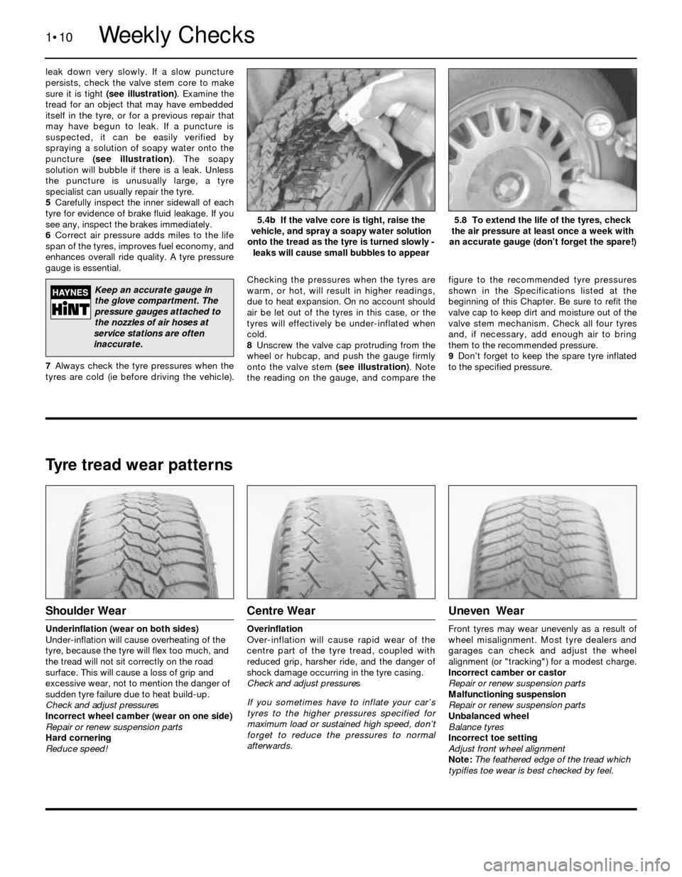
leak down very slowly. If a slow puncture
persists, check the valve stem core to make
sure it is tight (see illustration). Examine the
tread for an object that may have embedded
itself in the tyre, or for a previous repair that
may have begun to leak. If a puncture is
suspected, it can be easily verified by
spraying a solution of soapy water onto the
puncture (see illustration). The soapy
solution will bubble if there is a leak. Unless
the puncture is unusually large, a tyre
specialist can usually repair the tyre.
5Carefully inspect the inner sidewall of each
tyre for evidence of brake fluid leakage. If you
see any, inspect the brakes immediately.
6Correct air pressure adds miles to the life
span of the tyres, improves fuel economy, and
enhances overall ride quality. A tyre pressure
gauge is essential.
7Always check the tyre pressures when the
tyres are cold (ie before driving the vehicle).Checking the pressures when the tyres are
warm, or hot, will result in higher readings,
due to heat expansion. On no account should
air be let out of the tyres in this case, or the
tyres will effectively be under-inflated when
cold.
8Unscrew the valve cap protruding from the
wheel or hubcap, and push the gauge firmly
onto the valve stem (see illustration). Note
the reading on the gauge, and compare thefigure to the recommended tyre pressures
shown in the Specifications listed at the
beginning of this Chapter. Be sure to refit the
valve cap to keep dirt and moisture out of the
valve stem mechanism. Check all four tyres
and, if necessary, add enough air to bring
them to the recommended pressure.
9Don’t forget to keep the spare tyre inflated
to the specified pressure.
1•10
5.8 To extend the life of the tyres, check
the air pressure at least once a week with
an accurate gauge (don’t forget the spare!)5.4b If the valve core is tight, raise the
vehicle, and spray a soapy water solution
onto the tread as the tyre is turned slowly -
leaks will cause small bubbles to appear
Tyre tread wear patterns
Shoulder Wear
Underinflation (wear on both sides)
Under-inflation will cause overheating of the
tyre, because the tyre will flex too much, and
the tread will not sit correctly on the road
surface. This will cause a loss of grip and
excessive wear, not to mention the danger of
sudden tyre failure due to heat build-up.
Check and adjust pressures
Incorrect wheel camber (wear on one side)
Repair or renew suspension parts
Hard cornering
Reduce speed!
Centre Wear
Overinflation
Over-inflation will cause rapid wear of the
centre part of the tyre tread, coupled with
reduced grip, harsher ride, and the danger of
shock damage occurring in the tyre casing.
Check and adjust pressures
If you sometimes have to inflate your car’s
tyres to the higher pressures specified for
maximum load or sustained high speed, don’t
forget to reduce the pressures to normal
afterwards.
Uneven Wear
Front tyres may wear unevenly as a result of
wheel misalignment. Most tyre dealers and
garages can check and adjust the wheel
alignment (or "tracking") for a modest charge.
Incorrect camber or castor
Repair or renew suspension parts
Malfunctioning suspension
Repair or renew suspension parts
Unbalanced wheel
Balance tyres
Incorrect toe setting
Adjust front wheel alignment
Note: The feathered edge of the tread which
typifies toe wear is best checked by feel.
Weekly Checks
Keep an accurate gauge in
the glove compartment. The
pressure gauges attached to
the nozzles of air hoses at
service stations are often
inaccurate.
Page 22 of 228
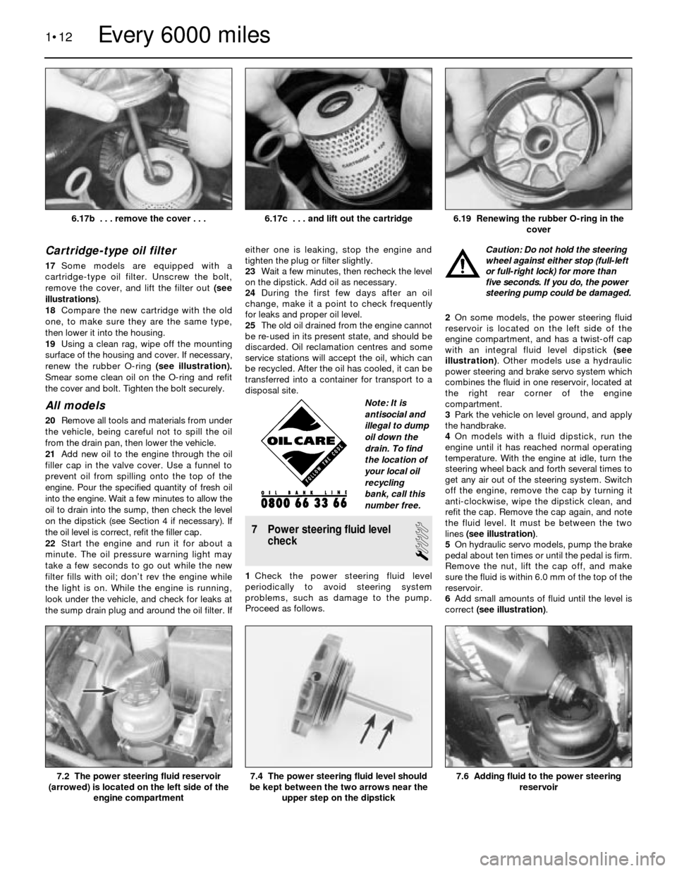
Cartridge-type oil filter
17Some models are equipped with a
cartridge-type oil filter. Unscrew the bolt,
remove the cover, and lift the filter out (see
illustrations).
18Compare the new cartridge with the old
one, to make sure they are the same type,
then lower it into the housing.
19Using a clean rag, wipe off the mounting
surface of the housing and cover. If necessary,
renew the rubber O-ring (see illustration).
Smear some clean oil on the O-ring and refit
the cover and bolt. Tighten the bolt securely.
All models
20Remove all tools and materials from under
the vehicle, being careful not to spill the oil
from the drain pan, then lower the vehicle.
21Add new oil to the engine through the oil
filler cap in the valve cover. Use a funnel to
prevent oil from spilling onto the top of the
engine. Pour the specified quantity of fresh oil
into the engine. Wait a few minutes to allow the
oil to drain into the sump, then check the level
on the dipstick (see Section 4 if necessary). If
the oil level is correct, refit the filler cap.
22Start the engine and run it for about a
minute. The oil pressure warning light may
take a few seconds to go out while the new
filter fills with oil; don’t rev the engine while
the light is on. While the engine is running,
look under the vehicle, and check for leaks at
the sump drain plug and around the oil filter. Ifeither one is leaking, stop the engine and
tighten the plug or filter slightly.
23Wait a few minutes, then recheck the level
on the dipstick. Add oil as necessary.
24During the first few days after an oil
change, make it a point to check frequently
for leaks and proper oil level.
25The old oil drained from the engine cannot
be re-used in its present state, and should be
discarded. Oil reclamation centres and some
service stations will accept the oil, which can
be recycled. After the oil has cooled, it can be
transferred into a container for transport to a
disposal site.
7 Power steering fluid level
check
1
1Check the power steering fluid level
periodically to avoid steering system
problems, such as damage to the pump.
Proceed as follows.Caution: Do not hold the steering
wheel against either stop (full-left
or full-right lock) for more than
five seconds. If you do, the power
steering pump could be damaged.
2On some models, the power steering fluid
reservoir is located on the left side of the
engine compartment, and has a twist-off cap
with an integral fluid level dipstick (see
illustration). Other models use a hydraulic
power steering and brake servo system which
combines the fluid in one reservoir, located at
the right rear corner of the engine
compartment.
3Park the vehicle on level ground, and apply
the handbrake.
4On models with a fluid dipstick, run the
engine until it has reached normal operating
temperature. With the engine at idle, turn the
steering wheel back and forth several times to
get any air out of the steering system. Switch
off the engine, remove the cap by turning it
anti-clockwise, wipe the dipstick clean, and
refit the cap. Remove the cap again, and note
the fluid level. It must be between the two
lines (see illustration).
5On hydraulic servo models, pump the brake
pedal about ten times or until the pedal is firm.
Remove the nut, lift the cap off, and make
sure the fluid is within 6.0 mm of the top of the
reservoir.
6Add small amounts of fluid until the level is
correct (see illustration).
1•12
7.6 Adding fluid to the power steering
reservoir7.4 The power steering fluid level should
be kept between the two arrows near the
upper step on the dipstick7.2 The power steering fluid reservoir
(arrowed) is located on the left side of the
engine compartment
6.19 Renewing the rubber O-ring in the
cover6.17c . . . and lift out the cartridge
Every 6000 miles
6.17b . . . remove the cover . . .
Note: It is
antisocial and
illegal to dump
oil down the
drain. To find
the location of
your local oil
recycling
bank, call this
number free.
Page 23 of 228
Caution: Do not overfill the
reservoir. If too much fluid is
added, remove the excess with a
clean syringe. Refit the cap.
7If frequent topping-up is needed, check the
power steering hoses and connections for
leaks and wear (see Section 10).
8Check the condition and tension of the
drivebelt (see Section 11).
8 Automatic transmission fluid
level check
1
Caution: The use of transmission
fluid other than the type listed in
this Chapter’s Specifications
could result in transmission
malfunctions or failure.
1The automatic transmission fluid should be
carefully maintained. Low fluid level can lead
to slipping or loss of drive, while overfilling
can cause foaming and loss of fluid. Either
condition can cause transmission damage.
2Since transmission fluid expands as it heats
up, the fluid level should only be checked
when the transmission is warm (at normal
operating temperature). If the vehicle has just
been driven over 20 miles (32 km), the
transmission can be considered warm. You
can also check the fluid level when the
transmission is cold. If the vehicle has not
been driven for over five hours and the fluid is
about room temperature (20°C), the
transmission is cold. However, the fluid level
is normally checked with the transmission
warm, to ensure accurate results.
Caution: If the vehicle has just
been driven for a long time at
high speed or in city traffic, in hot
weather, or if it has been pulling
a trailer, an accurate fluid level reading
cannot be obtained. Allow the trans-
mission to cool down for about 30 minutes.
3Immediately after driving the vehicle, park it
on a level surface, apply the handbrake and
start the engine. While the engine is idling,
depress the brake pedal and move theselector lever through all the gear ranges,
beginning and ending in Park.
4The automatic transmission dipstick tube is
located in the left rear corner of the engine
compartment.
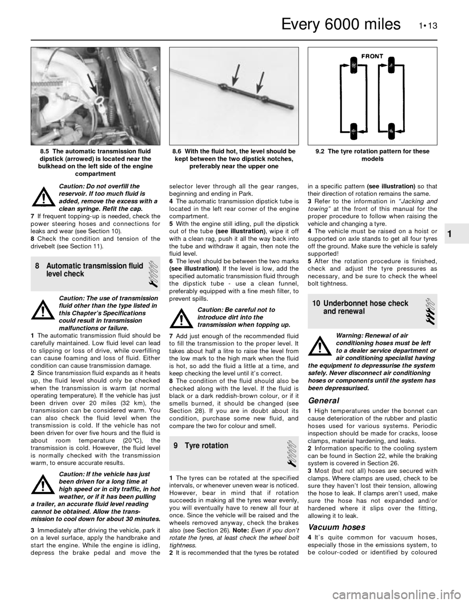
5With the engine still idling, pull the dipstick
out of the tube (see illustration), wipe it off
with a clean rag, push it all the way back into
the tube and withdraw it again, then note the
fluid level.
6The level should be between the two marks
(see illustration). If the level is low, add the
specified automatic transmission fluid through
the dipstick tube - use a clean funnel,
preferably equipped with a fine mesh filter, to
prevent spills.
Caution: Be careful not to
introduce dirt into the
transmission when topping up.
7Add just enough of the recommended fluid
to fill the transmission to the proper level. It
takes about half a litre to raise the level from
the low mark to the high mark when the fluid
is hot, so add the fluid a little at a time, and
keep checking the level until it’s correct.
8The condition of the fluid should also be
checked along with the level. If the fluid is
black or a dark reddish-brown colour, or if it
smells burned, it should be changed (see
Section 28). If you are in doubt about its
condition, purchase some new fluid, and
compare the two for colour and smell.
9 Tyre rotation
1
1The tyres can be rotated at the specified
intervals, or whenever uneven wear is noticed.
However, bear in mind that if rotation
succeeds in making all the tyres wear evenly,
you will eventually have to renew all four at
once. Since the vehicle will be raised and the
wheels removed anyway, check the brakes
also (see Section 26). Note: Even if you don’t
rotate the tyres, at least check the wheel bolt
tightness.
2It is recommended that the tyres be rotatedin a specific pattern (see illustration)so that
their direction of rotation remains the same.
3Refer to the information in “Jacking and
towing”at the front of this manual for the
proper procedure to follow when raising the
vehicle and changing a tyre.
4The vehicle must be raised on a hoist or
supported on axle stands to get all four tyres
off the ground. Make sure the vehicle is safely
supported!
5After the rotation procedure is finished,
check and adjust the tyre pressures as
necessary, and be sure to check the wheel
bolt tightness.
10 Underbonnet hose check
and renewal
3
Warning: Renewal of air
conditioning hoses must be left
to a dealer service department or
air conditioning specialist having
the equipment to depressurise the system
safely. Never disconnect air conditioning
hoses or components until the system has
been depressurised.
General
1High temperatures under the bonnet can
cause deterioration of the rubber and plastic
hoses used for various systems. Periodic
inspection should be made for cracks, loose
clamps, material hardening, and leaks.
2Information specific to the cooling system
can be found in Section 22, while the braking
system is covered in Section 26.
3Most (but not all) hoses are secured with
clamps. Where clamps are used, check to be
sure they haven’t lost their tension, allowing
the hose to leak. If clamps aren’t used, make
sure the hose has not expanded and/or
hardened where it slips over the fitting,
allowing it to leak.
Vacuum hoses
4It’s quite common for vacuum hoses,
especially those in the emissions system, to
be colour-coded or identified by coloured
1•13
9.2 The tyre rotation pattern for these
models8.6 With the fluid hot, the level should be
kept between the two dipstick notches,
preferably near the upper one8.5 The automatic transmission fluid
dipstick (arrowed) is located near the
bulkhead on the left side of the engine
compartment
1
Every 6000 miles
Page 24 of 228
stripes moulded into them. Various systems
require hoses with different wall thicknesses,
collapse resistance and temperature
resistance. When fitting new hoses, be sure
the new ones are made of the same material.
5Often the only effective way to check a
hose is to remove it completely from the
vehicle. If more than one hose is removed, be
sure to label the hoses and fittings to ensure
correct refitting.
6When checking vacuum hoses, be sure to
include any plastic T-fittings in the check.
Inspect the connections for cracks which
could cause leakage.
7A small piece of vacuum hose can be used
as a stethoscope to detect vacuum leaks.
Hold one end of the hose to your ear and
probe around vacuum hoses and fittings,
listening for the “hissing” sound characteristic
of a vacuum leak.
Warning: When probing with the
vacuum hose stethoscope, be
careful not to touch moving
engine components such as the
drivebelt, cooling fan, etc.
Fuel hoses
Warning: There are certain
precautions which must be taken
when servicing or inspecting fuel
system components. Work in a
well-ventilated area, and do not allow open
flames (cigarettes, appliance pilot lights,
etc.) or bare light bulbs near the work
area. Mop up any spills immediately, and
do not store fuel-soaked rags where they
could ignite. If you spill any fuel on your
skin, rinse it off immediately with soap and
water. When you perform any kind of work
on the fuel system, wear safety glasses,
and have a fire extinguisher on hand.
8The fuel hoses are usually under pressure,
so if any fuel hoses are to be disconnected,
be prepared to catch spilled fuel.
Warning: On vehicles equipped
with fuel injection, you must
depressurise the fuel system
before servicing the fuel hoses.
Refer to Chapter 4 for details.9Check all rubber fuel hoses for deterioration
and chafing. Check especially for cracks in
areas where the hose bends, and just before
connectors, such as where a hose attaches to
the fuel pump or fuel filter, for example.
10Only high-quality fuel hose should be
used. Never, under any circumstances, use
unreinforced vacuum hose, clear plastic
tubing or water hose for fuel hoses.
11Band-type clamps are commonly used on
fuel hoses. These clamps often lose their
tension over a period of time, and can be
“sprung” during removal. Renew all band-type
clamps with screw clamps whenever a hose is
renewed.
Metal lines
12Sections of metal line are often used
between the fuel pump and fuel injection
system. Check carefully to make sure the line
isn’t bent, crimped or cracked.
13If a section of metal line must be renewed,
use seamless steel tubing only, since copper
and aluminium tubing do not have the
strength necessary to withstand the vibration
caused by the engine.
14Check the metal brake lines where they
enter the master cylinder and brake
proportioning or ABS unit (if used) for cracks
in the lines and loose fittings. Any sign of
brake fluid leakage calls for an immediate
thorough inspection of the braking system.
Power steering hoses
15Check the power steering hoses for leaks,
loose connections and worn clamps. Tighten
loose connections. Worn clamps or leaky
hoses should be renewed.
11 Drivebelt check, adjustment
and renewal
1
Check
1The drivebelts, sometimes called V-belts or
simply “fan” belts, are located at the front of
the engine, and play an important role in the
overall operation of the vehicle and itscomponents. Due to their function and
material make-up, the belts are prone to
failure after a period of time, and should be
inspected and adjusted periodically to prevent
major engine damage.
2The number of belts used on a particular
vehicle depends on the accessories fitted.
Drivebelts are used to turn the alternator,
power steering pump, water pump, and air
conditioning compressor. Depending on the
pulley arrangement, a single belt may be used
to drive more than one of these components.
3With the engine switched off, open the
bonnet and locate the various belts at the
front of the engine. Using your fingers (and a
torch, if necessary), move along the belts,
checking for cracks and separation of the belt
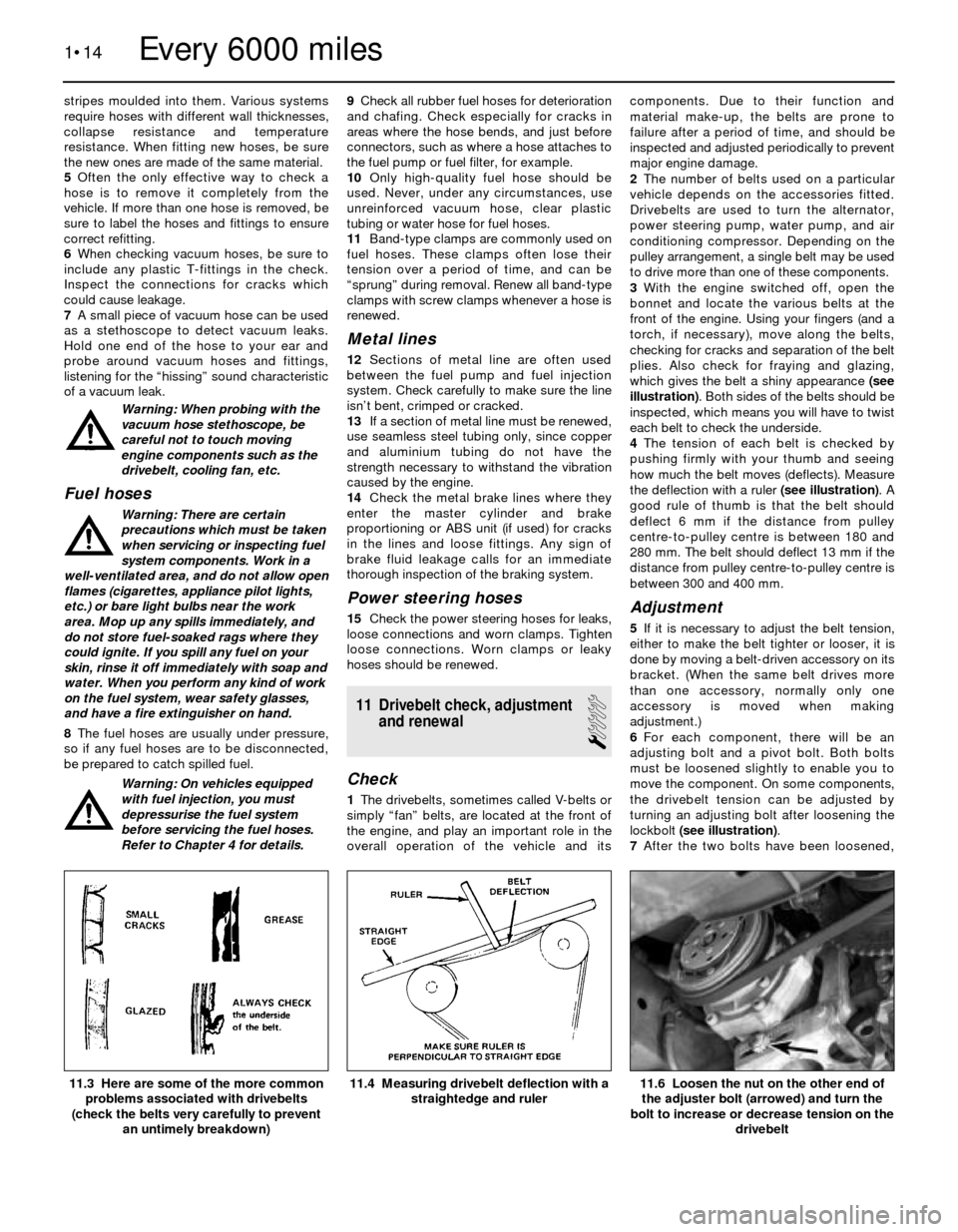
plies. Also check for fraying and glazing,
which gives the belt a shiny appearance (see
illustration). Both sides of the belts should be
inspected, which means you will have to twist
each belt to check the underside.
4The tension of each belt is checked by
pushing firmly with your thumb and seeing
how much the belt moves (deflects). Measure
the deflection with a ruler (see illustration). A
good rule of thumb is that the belt should
deflect 6 mm if the distance from pulley
centre-to-pulley centre is between 180 and
280 mm. The belt should deflect 13 mm if the
distance from pulley centre-to-pulley centre is
between 300 and 400 mm.
Adjustment
5If it is necessary to adjust the belt tension,
either to make the belt tighter or looser, it is
done by moving a belt-driven accessory on its
bracket. (When the same belt drives more
than one accessory, normally only one
accessory is moved when making
adjustment.)
6For each component, there will be an
adjusting bolt and a pivot bolt. Both bolts
must be loosened slightly to enable you to
move the component. On some components,
the drivebelt tension can be adjusted by
turning an adjusting bolt after loosening the
lockbolt (see illustration).
7After the two bolts have been loosened,
1•14
11.6 Loosen the nut on the other end of
the adjuster bolt (arrowed) and turn the
bolt to increase or decrease tension on the
drivebelt11.4 Measuring drivebelt deflection with a
straightedge and ruler11.3 Here are some of the more common
problems associated with drivebelts
(check the belts very carefully to prevent
an untimely breakdown)
Every 6000 miles