tow BMW 3 SERIES 1990 E30 Owner's Manual
[x] Cancel search | Manufacturer: BMW, Model Year: 1990, Model line: 3 SERIES, Model: BMW 3 SERIES 1990 E30Pages: 228, PDF Size: 7.04 MB
Page 81 of 228
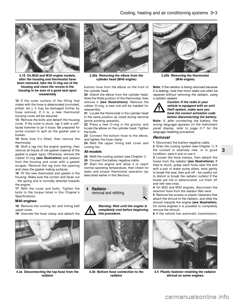
12If the outer surface of the fitting that
mates with the hose is deteriorated (corroded,
pitted, etc.), it may be damaged further by
hose removal. If it is, a new thermostat
housing cover will be required.
13Remove the bolts and detach the housing
cover. If the cover is stuck, tap it with a soft-
faced hammer to jar it loose. Be prepared for
some coolant to spill as the gasket seal is
broken.
14Note how it’s fitted, then remove the
thermostat.
15Stuff a rag into the engine opening, then
remove all traces of old gasket material (if the
gasket is paper type). Otherwise, remove the
rubber O-ring (see illustration)and sealant
from the housing and cover with a gasket
scraper. Remove the rag from the opening
and clean the gasket mating surfaces.
16Fit the new thermostat and gasket in the
housing. Make sure the correct end faces out
- the spring end is normally directed towards
the engine.
17Refit the cover and bolts. Tighten the
bolts to the torque listed in this Chapter’s
Specifications.
M40 engines
18Remove the cooling fan and timing belt
upper cover.
19Unscrew the hose clamp and detach thebottom hose from the elbow on the front of
the cylinder head.
20Unbolt the elbow from the cylinder head.
Note the fitted position of the thermostat, then
remove it (see illustrations). Remove the
rubber O-ring; a new one will be needed for
reassembly.
21Locate the thermostat in the cylinder head
in the same position as noted during removal
(arrow pointing upwards).
22Press a new O-ring in the groove, and
locate the elbow on the cylinder head. Tighten
the bolts.
23Connect the bottom hose to the elbow,
and tighten the hose clamp.
24Refit the upper timing belt cover and
cooling fan.
All models
25Refill the cooling system (see Chapter 1).
26Connect the battery negative cable.
27Start the engine and allow it to reach
normal operating temperature, then check for
leaks and proper thermostat operation (as
described earlier in this Section).
4 Radiator-
removal and refitting
1
Warning: Wait until the engine is
completely cool before beginning
this procedure.Note: If the radiator is being removed because
it is leaking, note that minor leaks can often be
repaired without removing the radiator, using
a radiator sealant.
Caution: If the radio in your
vehicle is equipped with an anti-
theft system, make sure you
have the correct activation code
before disconnecting the battery.
Note: If, after connecting the battery, the
wrong language appears on the instrument
panel display, refer to page 0-7 for the
language resetting procedure.
Removal
1Disconnect the battery negative cable.
2Drain the cooling system (see Chapter 1). If
the coolant is relatively new, or in good
condition, save it and re-use it.
3Loosen the hose clamps, then detach the
hoses from the radiator (see illustrations). If
they’re stuck, grasp each hose near the end
with a pair of water pump pliers, twist gently
to break the seal, then pull off - be careful not
to distort or break the radiator outlets! If the
hoses are old or deteriorated, cut them off
and refit new ones.
4On M20 and M30 engines, disconnect the
reservoir hose from the radiator filler neck.
5Remove the screws or plastic fasteners that
attach the shroud to the radiator, and slide the
shroud towards the engine (see illustration).
On some engines it is possible to completely
remove the shroud.
6If the vehicle has automatic transmission,
Cooling, heating and air conditioning systems 3•3
3.20b Removing the thermostat
(M40 engine)3.20a Removing the elbow from the
cylinder head (M40 engine)3.15 On M20 and M30 engine models,
after the housing and thermostat have
been removed, take the O-ring out of the
housing and clean the recess in the
housing to be sure of a good seal upon
reassembly
4.5 Plastic fastener retaining the radiator
shroud on some engines4.3b Bottom hose connection to the
radiator4.3a Disconnecting the top hose from the
radiator
3
Page 83 of 228
3-Series models
14Remove the radiator grille assembly (see
Chapter 11).
15Unbolt and remove the fan bracket and
shroud assembly from the radiator (see
Section 5).
16Remove the radiator (see Section 4).
17Unbolt the air conditioning condenser
mounting bolts, where applicable. Do not
remove the condenser or disconnect any
refrigerant lines from the condenser.
18Carefully pull the condenser back towards
the engine, slightly, to gain access to lift the
auxiliary fan.
19Disconnect the fan motor electrical
connection and remove the auxiliary fan.
20Refitting is the reverse of removal.
5-Series models
21Remove the screws and trim panel in front
of the radiator.
22Unbolt the fan assembly from the
condenser mounting points.
23Disconnect the fan electrical connector.
24Remove the fan and housing from the car,
being careful not to damage the air
conditioning condenser (when applicable)
while removing the fan.
25Refitting is the reverse of removal.
Mechanical fan with viscous clutch
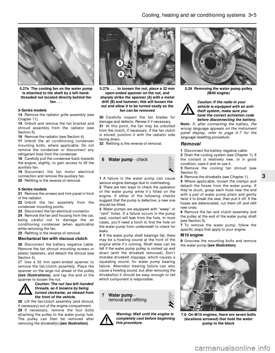
26Disconnect the battery negative cable.
Remove the fan shroud mounting screws or
plastic fasteners, and detach the shroud (see
Section 4).
27 Use a 32 mm open-ended spanner to
remove the fan/clutch assembly. Place the
spanner on the large nut ahead of the pulley
(see illustrations), and tap the end of the
spanner to loosen the nut.
Caution: The nut has left-handed
threads, so it loosens by being
turned clockwise, as viewed from
the front of the vehicle.
28Lift the fan/clutch assembly (and shroud,
if necessary) out of the engine compartment.
29If necessary, remove the four bolts
attaching the pulley to the water pump hub.
The pulley can then be removed after
removing the drivebelt(s) (see illustration).30Carefully inspect the fan blades for
damage and defects. Renew it if necessary.
31At this point, the fan may be unbolted
from the clutch, if necessary. If the fan clutch
is stored, position it with the radiator side
facing down.
32Refitting is the reverse of removal.
6 Water pump- check
1
1A failure in the water pump can cause
serious engine damage due to overheating.
2There are two ways to check the operation
of the water pump while it’s fitted on the
engine. If either of the following checks
suggest that the pump is defective, a new one
should be fitted.
3Water pumps are equipped with “weep” or
“vent” holes. If a failure occurs in the pump
seal, coolant will leak from the hole. In most
cases, you’ll need a torch to find the hole on
the water pump from underneath to check for
leaks.
4If the water pump shaft bearings fail, there
may be a howling sound at the front of the
engine while it’s running. Shaft wear can be
felt if the water pump pulley is rocked up and
down (with the drivebelt removed). Don’t
mistake drivebelt slippage, which causes a
squealing sound, for water pump bearing
failure. Alternator bearing failure can also
cause a howling sound, but after removing the
drivebelt(s) it should be easy enough to tell
which component is responsible.
7 Water pump-
removal and refitting
2
Warning: Wait until the engine is
completely cool before beginning
this procedure.Caution: If the radio in your
vehicle is equipped with an anti-
theft system, make sure you
have the correct activation code
before disconnecting the battery.
Note: If, after connecting the battery, the
wrong language appears on the instrument
panel display, refer to page 0-7 for the
language resetting procedure.
Removal
1Disconnect the battery negative cable.
2Drain the cooling system (see Chapter 1). If
the coolant is relatively new, or in good
condition, save it and re-use it.
3Remove the cooling fan shroud (see
Section 5).
4Remove the drivebelts (see Chapter 1).
5Where applicable, loosen the clamps and
detach the hoses from the water pump. If
they’re stuck, grasp each hose near the end
with a pair of water pump pliers and gently
twist it to break the seal, then pull it off. If the
hoses are deteriorated, cut them off and refit
new ones.
6Remove the fan and clutch assembly and
the pulley at the end of the water pump shaft
(see Section 5).
7To remove the water pump, follow the
specific steps that apply to your engine.
M10 engine
8Unscrew the mounting bolts and remove
the water pump (see illustration).
Cooling, heating and air conditioning systems 3•5
5.29 Removing the water pump pulley
(M40 engine)5.27b . . . to loosen the nut, place a 32 mm
open-ended spanner on the nut, and
sharply strike the spanner (A) with a metal
drift (B) and hammer; this will loosen the
nut and allow it to be turned easily so the
fan can be removed5.27a The cooling fan on the water pump
is attached to the shaft by a left-hand-
threaded nut located directly behind the
fan . . .
7.8 On M10 engines, there are seven bolts
(locations arrowed) that hold the water
pump to the block
3
Page 84 of 228
M20 engine
9Remove the distributor cap and HT leads,
ignition rotor and dust shield (see Chapter 1).
10Where applicable, remove the timing
sensor (see Chapter 5).
11Remove the timing belt upper cover (see
Chapter 2A).
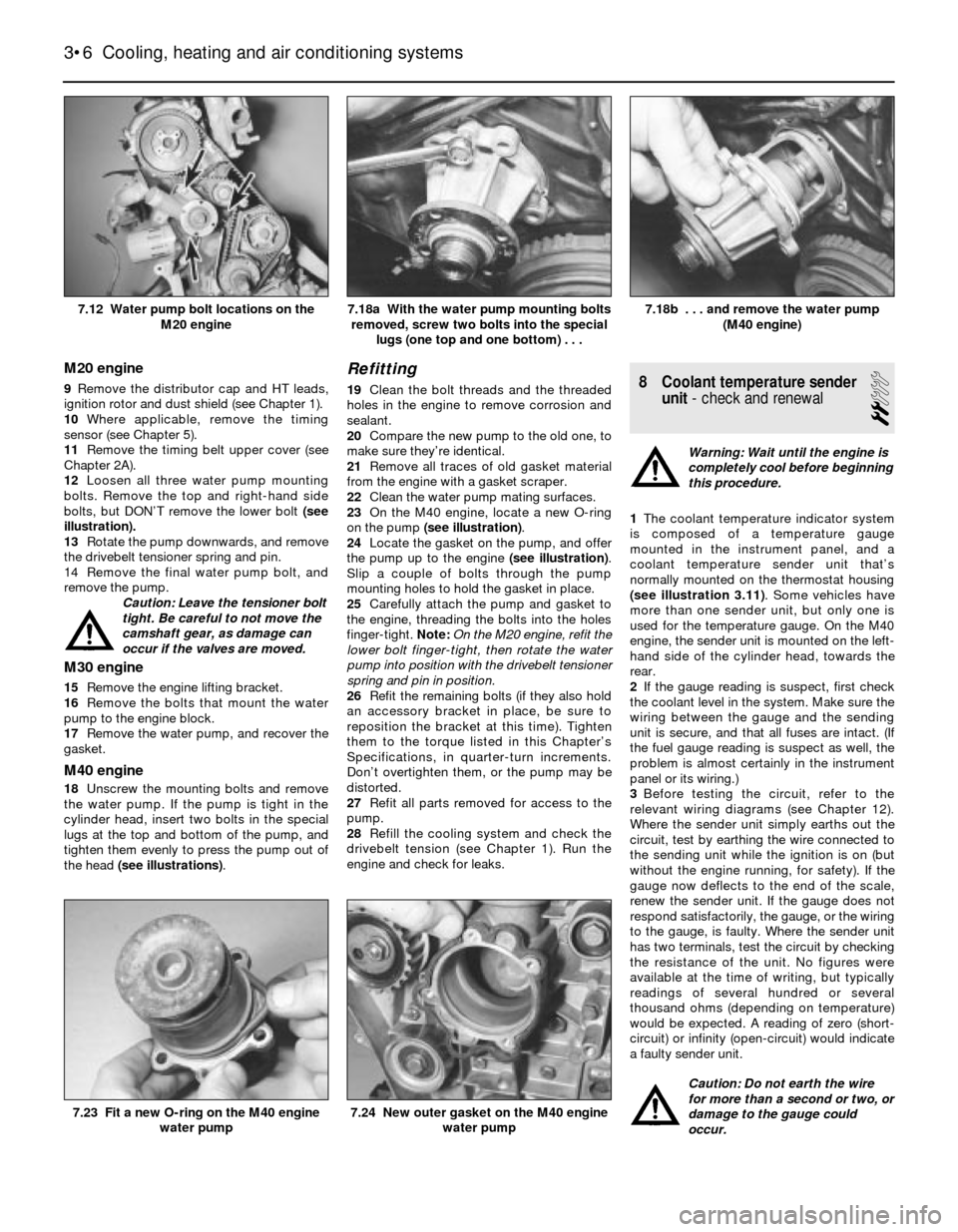
12Loosen all three water pump mounting
bolts. Remove the top and right-hand side
bolts, but DON’T remove the lower bolt (see
illustration).
13Rotate the pump downwards, and remove
the drivebelt tensioner spring and pin.
14 Remove the final water pump bolt, and
remove the pump.
Caution: Leave the tensioner bolt
tight. Be careful to not move the
camshaft gear, as damage can
occur if the valves are moved.
M30 engine
15Remove the engine lifting bracket.
16Remove the bolts that mount the water
pump to the engine block.
17Remove the water pump, and recover the
gasket.
M40 engine
18Unscrew the mounting bolts and remove
the water pump. If the pump is tight in the
cylinder head, insert two bolts in the special
lugs at the top and bottom of the pump, and
tighten them evenly to press the pump out of
the head (see illustrations).
Refitting
19Clean the bolt threads and the threaded
holes in the engine to remove corrosion and
sealant.
20Compare the new pump to the old one, to
make sure they’re identical.
21Remove all traces of old gasket material
from the engine with a gasket scraper.
22Clean the water pump mating surfaces.
23On the M40 engine, locate a new O-ring
on the pump (see illustration).
24Locate the gasket on the pump, and offer
the pump up to the engine (see illustration).
Slip a couple of bolts through the pump
mounting holes to hold the gasket in place.
25Carefully attach the pump and gasket to
the engine, threading the bolts into the holes
finger-tight.Note:On the M20 engine, refit the
lower bolt finger-tight, then rotate the water
pump into position with the drivebelt tensioner
spring and pin in position.
26Refit the remaining bolts (if they also hold
an accessory bracket in place, be sure to
reposition the bracket at this time). Tighten
them to the torque listed in this Chapter’s
Specifications, in quarter-turn increments.
Don’t overtighten them, or the pump may be
distorted.
27Refit all parts removed for access to the
pump.
28Refill the cooling system and check the
drivebelt tension (see Chapter 1). Run the
engine and check for leaks.8 Coolant temperature sender
unit- check and renewal
2
Warning: Wait until the engine is
completely cool before beginning
this procedure.
1The coolant temperature indicator system
is composed of a temperature gauge
mounted in the instrument panel, and a
coolant temperature sender unit that’s
normally mounted on the thermostat housing
(see illustration 3.11). Some vehicles have
more than one sender unit, but only one is
used for the temperature gauge. On the M40
engine, the sender unit is mounted on the left-
hand side of the cylinder head, towards the
rear.
2If the gauge reading is suspect, first check
the coolant level in the system. Make sure the
wiring between the gauge and the sending
unit is secure, and that all fuses are intact. (If
the fuel gauge reading is suspect as well, the
problem is almost certainly in the instrument
panel or its wiring.)
3Before testing the circuit, refer to the
relevant wiring diagrams (see Chapter 12).
Where the sender unit simply earths out the
circuit, test by earthing the wire connected to
the sending unit while the ignition is on (but
without the engine running, for safety). If the
gauge now deflects to the end of the scale,
renew the sender unit. If the gauge does not
respond satisfactorily, the gauge, or the wiring
to the gauge, is faulty. Where the sender unit
has two terminals, test the circuit by checking
the resistance of the unit. No figures were
available at the time of writing, but typically
readings of several hundred or several
thousand ohms (depending on temperature)
would be expected. A reading of zero (short-
circuit) or infinity (open-circuit) would indicate
a faulty sender unit.
Caution: Do not earth the wire
for more than a second or two, or
damage to the gauge could
occur.
3•6 Cooling, heating and air conditioning systems
7.24 New outer gasket on the M40 engine
water pump7.23 Fit a new O-ring on the M40 engine
water pump
7.18b . . . and remove the water pump
(M40 engine)7.18a With the water pump mounting bolts
removed, screw two bolts into the special
lugs (one top and one bottom) . . .7.12 Water pump bolt locations on the
M20 engine
Page 115 of 228
8Remove the hold-down nut or bolt and
clamp.
9Remove the distributor. Note:Do not rotate
the engine with the distributor out.
Refitting
10Before refitting the distributor, make
certain No 1 piston is still at TDC on the
compression stroke.
11Insert the distributor into the engine, with
the adjusting clamp centred over the hold-
down hole. Make allowance for the gear to
turn as the distributor is inserted.
12Refit the hold-down nut or bolt. The marks
previously made on the distributor housing,
and on the rotor and engine, should line up
before the nut or bolt is tightened.
13Refit the distributor cap.
14Connect the wiring for the distributor.
15Reconnect the spark plug HT leads.
16Reconnect the vacuum hoses as
previously marked.
17Check the ignition timing (see Section 7).
Motronic system
Removal
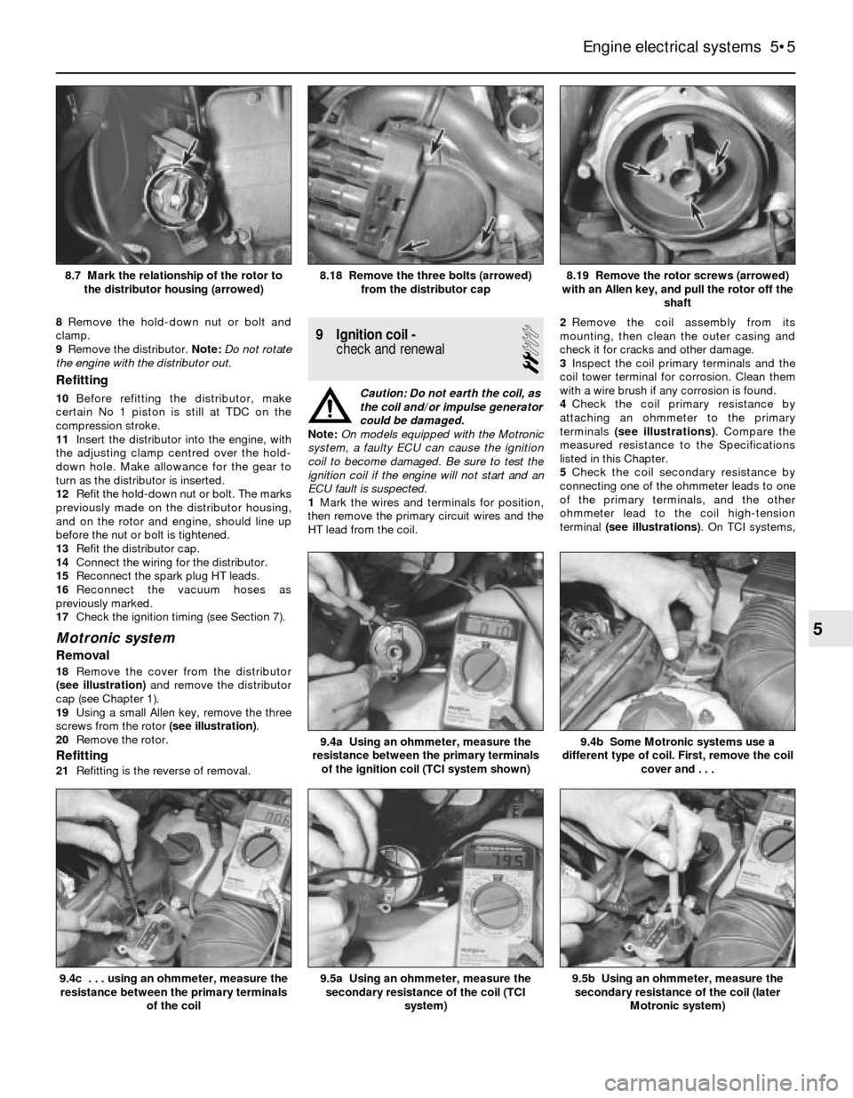
18Remove the cover from the distributor
(see illustration)and remove the distributor
cap (see Chapter 1).
19Using a small Allen key, remove the three
screws from the rotor (see illustration).
20Remove the rotor.
Refitting
21Refitting is the reverse of removal.
9 Ignition coil -
check and renewal
2
Caution: Do not earth the coil, as
the coil and/or impulse generator
could be damaged.
Note:On models equipped with the Motronic
system, a faulty ECU can cause the ignition
coil to become damaged. Be sure to test the
ignition coil if the engine will not start and an
ECU fault is suspected.
1Mark the wires and terminals for position,
then remove the primary circuit wires and the
HT lead from the coil.2Remove the coil assembly from its
mounting, then clean the outer casing and
check it for cracks and other damage.
3Inspect the coil primary terminals and the
coil tower terminal for corrosion. Clean them
with a wire brush if any corrosion is found.
4Check the coil primary resistance by
attaching an ohmmeter to the primary
terminals (see illustrations). Compare the
measured resistance to the Specifications
listed in this Chapter.
5Check the coil secondary resistance by
connecting one of the ohmmeter leads to one
of the primary terminals, and the other
ohmmeter lead to the coil high-tension
terminal (see illustrations). On TCI systems,
Engine electrical systems 5•5
8.19 Remove the rotor screws (arrowed)
with an Allen key, and pull the rotor off the
shaft8.18 Remove the three bolts (arrowed)
from the distributor cap8.7 Mark the relationship of the rotor to
the distributor housing (arrowed)
9.5b Using an ohmmeter, measure the
secondary resistance of the coil (later
Motronic system)9.5a Using an ohmmeter, measure the
secondary resistance of the coil (TCI
system)
9.4b Some Motronic systems use a
different type of coil. First, remove the coil
cover and . . .9.4a Using an ohmmeter, measure the
resistance between the primary terminals
of the ignition coil (TCI system shown)
9.4c . . . using an ohmmeter, measure the
resistance between the primary terminals
of the coil
5
Page 116 of 228
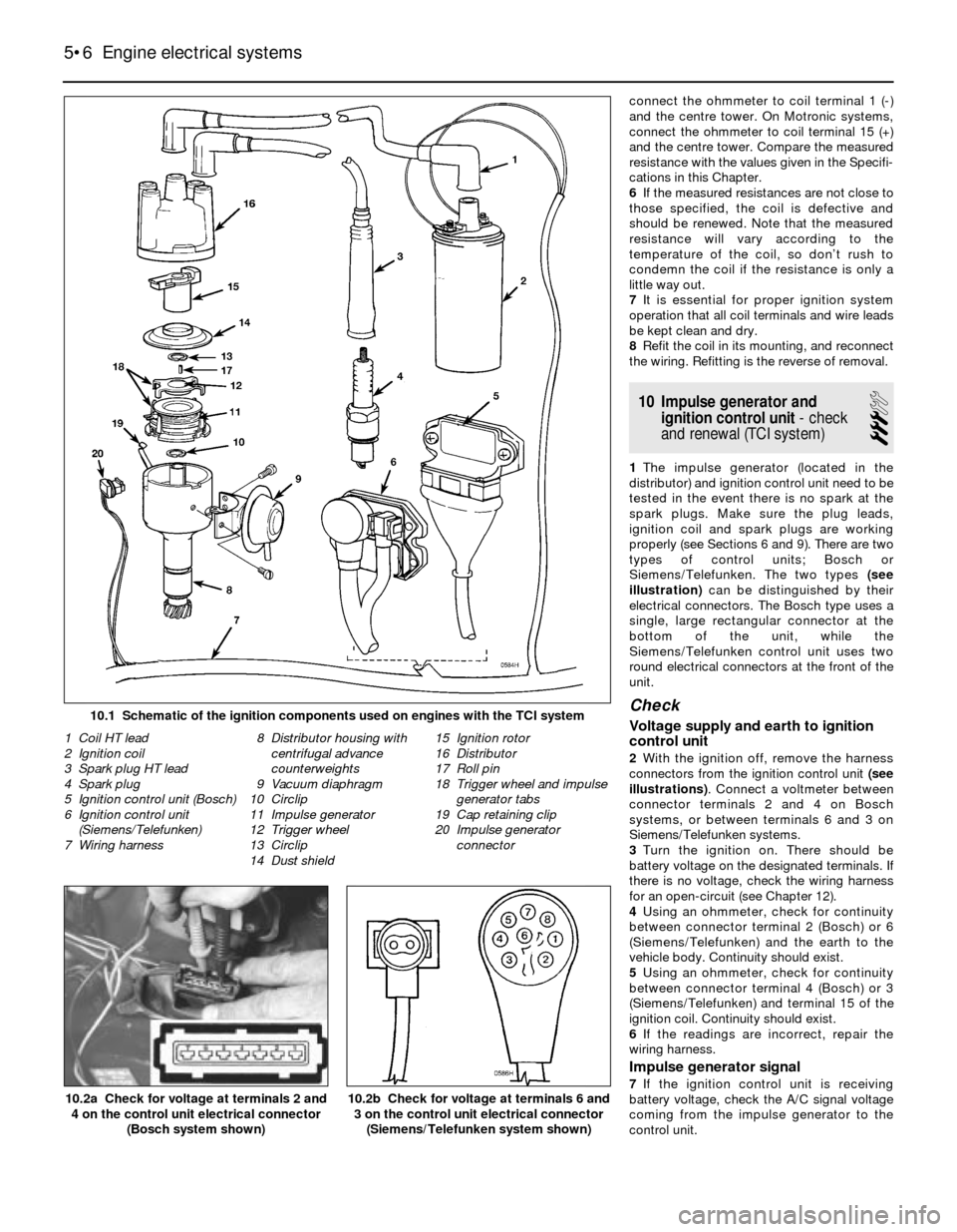
connect the ohmmeter to coil terminal 1 (-)
and the centre tower. On Motronic systems,
connect the ohmmeter to coil terminal 15 (+)
and the centre tower. Compare the measured
resistance with the values given in the Specifi-
cations in this Chapter.
6If the measured resistances are not close to
those specified, the coil is defective and
should be renewed. Note that the measured
resistance will vary according to the
temperature of the coil, so don’t rush to
condemn the coil if the resistance is only a
little way out.
7It is essential for proper ignition system
operation that all coil terminals and wire leads
be kept clean and dry.
8Refit the coil in its mounting, and reconnect
the wiring. Refitting is the reverse of removal.
10 Impulse generator and
ignition control unit- check
and renewal (TCI system)
3
1The impulse generator (located in the
distributor) and ignition control unit need to be
tested in the event there is no spark at the
spark plugs. Make sure the plug leads,
ignition coil and spark plugs are working
properly (see Sections 6 and 9). There are two
types of control units; Bosch or
Siemens/Telefunken. The two types (see
illustration)can be distinguished by their
electrical connectors. The Bosch type uses a
single, large rectangular connector at the
bottom of the unit, while the
Siemens/Telefunken control unit uses two
round electrical connectors at the front of the
unit.
Check
Voltage supply and earth to ignition
control unit
2With the ignition off, remove the harness
connectors from the ignition control unit (see
illustrations). Connect a voltmeter between
connector terminals 2 and 4 on Bosch
systems, or between terminals 6 and 3 on
Siemens/Telefunken systems.
3Turn the ignition on. There should be
battery voltage on the designated terminals. If
there is no voltage, check the wiring harness
for an open-circuit (see Chapter 12).
4Using an ohmmeter, check for continuity
between connector terminal 2 (Bosch) or 6
(Siemens/Telefunken) and the earth to the
vehicle body. Continuity should exist.
5Using an ohmmeter, check for continuity
between connector terminal 4 (Bosch) or 3
(Siemens/Telefunken) and terminal 15 of the
ignition coil. Continuity should exist.
6If the readings are incorrect, repair the
wiring harness.
Impulse generator signal
7If the ignition control unit is receiving
battery voltage, check the A/C signal voltage
coming from the impulse generator to the
control unit.
5•6 Engine electrical systems
10.2b Check for voltage at terminals 6 and
3 on the control unit electrical connector
(Siemens/Telefunken system shown)10.2a Check for voltage at terminals 2 and
4 on the control unit electrical connector
(Bosch system shown)
1 Coil HT lead
2 Ignition coil
3 Spark plug HT lead
4 Spark plug
5 Ignition control unit (Bosch)
6 Ignition control unit
(Siemens/Telefunken)
7 Wiring harness8 Distributor housing with
centrifugal advance
counterweights
9 Vacuum diaphragm
10 Circlip
11 Impulse generator
12 Trigger wheel
13 Circlip
14 Dust shield15 Ignition rotor
16 Distributor
17 Roll pin
18 Trigger wheel and impulse
generator tabs
19 Cap retaining clip
20 Impulse generator
connector
10.1 Schematic of the ignition components used on engines with the TCI system
Page 128 of 228
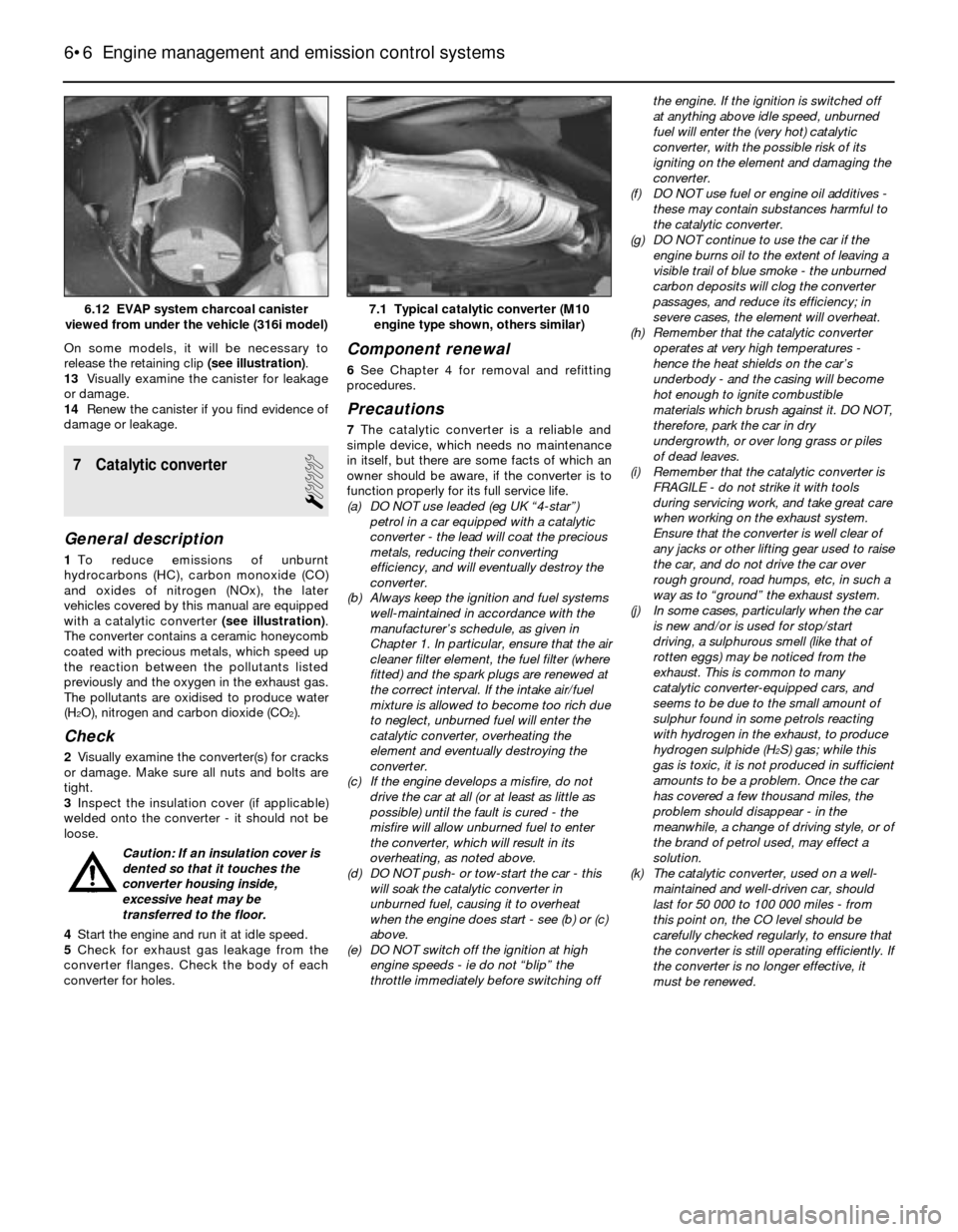
On some models, it will be necessary to
release the retaining clip (see illustration).
13Visually examine the canister for leakage
or damage.
14Renew the canister if you find evidence of
damage or leakage.
7 Catalytic converter
1
General description
1To reduce emissions of unburnt
hydrocarbons (HC), carbon monoxide (CO)
and oxides of nitrogen (NOx), the later
vehicles covered by this manual are equipped
with a catalytic converter (see illustration).
The converter contains a ceramic honeycomb
coated with precious metals, which speed up
the reaction between the pollutants listed
previously and the oxygen in the exhaust gas.
The pollutants are oxidised to produce water
(H
2O), nitrogen and carbon dioxide (CO2).
Check
2Visually examine the converter(s) for cracks
or damage. Make sure all nuts and bolts are
tight.
3Inspect the insulation cover (if applicable)
welded onto the converter - it should not be
loose.
Caution: If an insulation cover is
dented so that it touches the
converter housing inside,
excessive heat may be
transferred to the floor.
4Start the engine and run it at idle speed.
5Check for exhaust gas leakage from the
converter flanges. Check the body of each
converter for holes.
Component renewal
6See Chapter 4 for removal and refitting
procedures.
Precautions
7The catalytic converter is a reliable and
simple device, which needs no maintenance
in itself, but there are some facts of which an
owner should be aware, if the converter is to
function properly for its full service life.
(a) DO NOT use leaded (eg UK “4-star”)
petrol in a car equipped with a catalytic
converter - the lead will coat the precious
metals, reducing their converting
efficiency, and will eventually destroy the
converter.
(b) Always keep the ignition and fuel systems
well-maintained in accordance with the
manufacturer’s schedule, as given in
Chapter 1. In particular, ensure that the air
cleaner filter element, the fuel filter (where
fitted) and the spark plugs are renewed at
the correct interval. If the intake air/fuel
mixture is allowed to become too rich due
to neglect, unburned fuel will enter the
catalytic converter, overheating the
element and eventually destroying the
converter.
(c) If the engine develops a misfire, do not
drive the car at all (or at least as little as
possible) until the fault is cured - the
misfire will allow unburned fuel to enter
the converter, which will result in its
overheating, as noted above.
(d) DO NOT push- or tow-start the car - this
will soak the catalytic converter in
unburned fuel, causing it to overheat
when the engine does start - see (b) or (c)
above.
(e) DO NOT switch off the ignition at high
engine speeds - ie do not “blip” the
throttle immediately before switching offthe engine. If the ignition is switched off
at anything above idle speed, unburned
fuel will enter the (very hot) catalytic
converter, with the possible risk of its
igniting on the element and damaging the
converter.
(f) DO NOT use fuel or engine oil additives -
these may contain substances harmful to
the catalytic converter.
(g) DO NOT continue to use the car if the
engine burns oil to the extent of leaving a
visible trail of blue smoke - the unburned
carbon deposits will clog the converter
passages, and reduce its efficiency; in
severe cases, the element will overheat.
(h) Remember that the catalytic converter
operates at very high temperatures -
hence the heat shields on the car’s
underbody - and the casing will become
hot enough to ignite combustible
materials which brush against it. DO NOT,
therefore, park the car in dry
undergrowth, or over long grass or piles
of dead leaves.
(i) Remember that the catalytic converter is
FRAGILE - do not strike it with tools
during servicing work, and take great care
when working on the exhaust system.
Ensure that the converter is well clear of
any jacks or other lifting gear used to raise
the car, and do not drive the car over
rough ground, road humps, etc, in such a
way as to “ground” the exhaust system.
(j) In some cases, particularly when the car
is new and/or is used for stop/start
driving, a sulphurous smell (like that of
rotten eggs) may be noticed from the
exhaust. This is common to many
catalytic converter-equipped cars, and
seems to be due to the small amount of
sulphur found in some petrols reacting
with hydrogen in the exhaust, to produce
hydrogen sulphide (H
2S) gas; while this
gas is toxic, it is not produced in sufficient
amounts to be a problem. Once the car
has covered a few thousand miles, the
problem should disappear - in the
meanwhile, a change of driving style, or of
the brand of petrol used, may effect a
solution.
(k) The catalytic converter, used on a well-
maintained and well-driven car, should
last for 50 000 to 100 000 miles - from
this point on, the CO level should be
carefully checked regularly, to ensure that
the converter is still operating efficiently. If
the converter is no longer effective, it
must be renewed.
6•6 Engine management and emission control systems
7.1 Typical catalytic converter (M10
engine type shown, others similar)6.12 EVAP system charcoal canister
viewed from under the vehicle (316i model)
Page 133 of 228
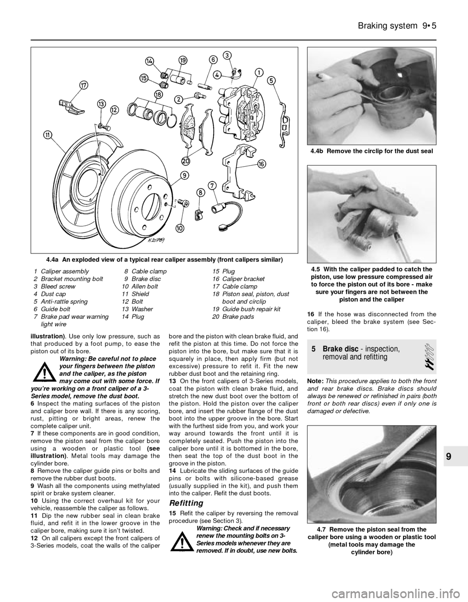
illustration). Use only low pressure, such as
that produced by a foot pump, to ease the
piston out of its bore.
Warning: Be careful not to place
your fingers between the piston
and the caliper, as the piston
may come out with some force. If
you’re working on a front caliper of a 3-
Series model, remove the dust boot.
6Inspect the mating surfaces of the piston
and caliper bore wall. If there is any scoring,
rust, pitting or bright areas, renew the
complete caliper unit.
7If these components are in good condition,
remove the piston seal from the caliper bore
using a wooden or plastic tool (see
illustration). Metal tools may damage the
cylinder bore.
8Remove the caliper guide pins or bolts and
remove the rubber dust boots.
9Wash all the components using methylated
spirit or brake system cleaner.
10Using the correct overhaul kit for your
vehicle, reassemble the caliper as follows.
11Dip the new rubber seal in clean brake
fluid, and refit it in the lower groove in the
caliper bore, making sure it isn’t twisted.
12On all calipers except the front calipers of
3-Series models, coat the walls of the caliperbore and the piston with clean brake fluid, and
refit the piston at this time. Do not force the
piston into the bore, but make sure that it is
squarely in place, then apply firm (but not
excessive) pressure to refit it. Fit the new
rubber dust boot and the retaining ring.
13On the front calipers of 3-Series models,
coat the piston with clean brake fluid, and
stretch the new dust boot over the bottom of
the piston. Hold the piston over the caliper
bore, and insert the rubber flange of the dust
boot into the upper groove in the bore. Start
with the furthest side from you, and work your
way around towards the front until it is
completely seated. Push the piston into the
caliper bore until it is bottomed in the bore,
then seat the top of the dust boot in the
groove in the piston.
14Lubricate the sliding surfaces of the guide
pins or bolts with silicone-based grease
(usually supplied in the kit), and push them
into the caliper. Refit the dust boots.
Refitting
15Refit the caliper by reversing the removal
procedure (see Section 3).
Warning: Check and if necessary
renew the mounting bolts on 3-
Series models whenever they are
removed. If in doubt, use new bolts.16If the hose was disconnected from the
caliper, bleed the brake system (see Sec-
tion 16).
5 Brake disc- inspection,
removal and refitting
2
Note:This procedure applies to both the front
and rear brake discs. Brake discs should
always be renewed or refinished in pairs (both
front or both rear discs) even if only one is
damaged or defective.
Braking system 9•5
4.4b Remove the circlip for the dust seal
4.4a An exploded view of a typical rear caliper assembly (front calipers similar)
4.7 Remove the piston seal from the
caliper bore using a wooden or plastic tool
(metal tools may damage the
cylinder bore)
1 Caliper assembly
2 Bracket mounting bolt
3 Bleed screw
4 Dust cap
5 Anti-rattle spring
6 Guide bolt
7 Brake pad wear warning
light wire8 Cable clamp
9 Brake disc
10 Allen bolt
11 Shield
12 Bolt
13 Washer
14 Plug15 Plug
16 Caliper bracket
17 Cable clamp
18 Piston seal, piston, dust
boot and circlip
19 Guide bush repair kit
20 Brake pads4.5 With the caliper padded to catch the
piston, use low pressure compressed air
to force the piston out of its bore - make
sure your fingers are not between the
piston and the caliper
9
Page 153 of 228
the longer side of the sleeve facing towards
the centre of the vehicle.
Refitting
12Refitting is the reverse of removal. Refit
the inner pivot bolt first. Don’t fully tighten the
nuts on the pivot bolts or the shock absorber
yet.
13Bleed the brakes as described in Chap-
ter 9.
14Support the trailing arm with a trolley jack,
and raise it to simulate normal ride height.
Tighten the bolts and nuts to the torques
listed in this Chapter’s Specifications.
15 Rear wheel bearings-
renewal
4
3-Series models
1Loosen the driveshaft nut and the rear
wheel bolts, then chock the front wheels.
Raise the rear of the vehicle and place it
securely on axle stands. Remove the rear
wheel. Note: Depending on the type of rear
wheel, it may be necessary to remove the
wheel first, remove the hubcap, then refit the
wheel and loosen the driveshaft nut.
2Remove the driveshaft (see Chapter 8).3On models with rear brake drums, remove
the drum. On models with rear disc brakes,
remove the brake caliper and mounting
bracket. Don’t disconnect the hose. Hang the
caliper out of the way with a piece of wire.
Remove the brake disc (see Chapter 9).
Working from behind, drive the wheel hub out
of the wheel bearing with a large socket or a
piece of pipe.
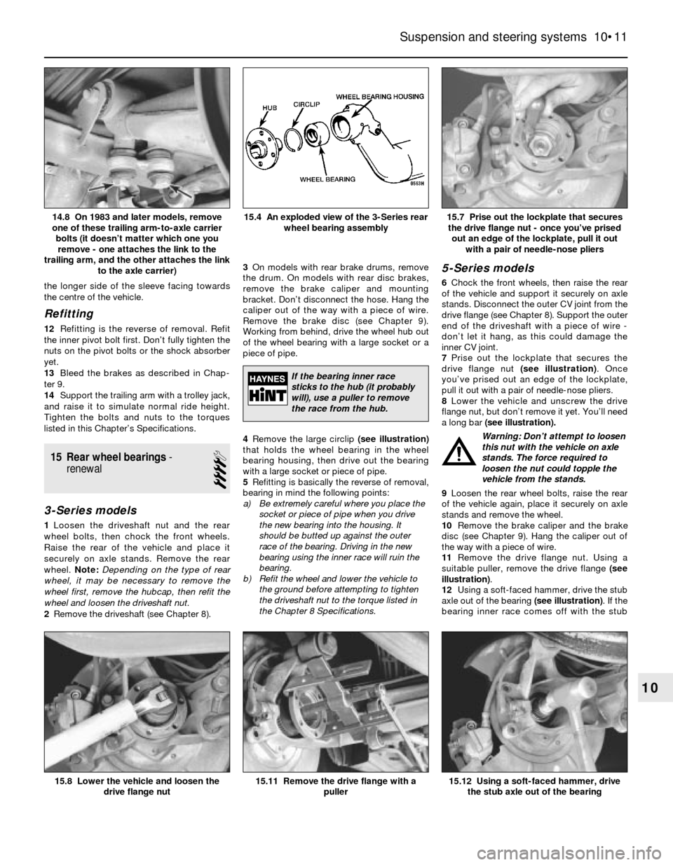
4Remove the large circlip (see illustration)
that holds the wheel bearing in the wheel
bearing housing, then drive out the bearing
with a large socket or piece of pipe.
5Refitting is basically the reverse of removal,
bearing in mind the following points:
a) Be extremely careful where you place the
socket or piece of pipe when you drive
the new bearing into the housing. It
should be butted up against the outer
race of the bearing. Driving in the new
bearing using the inner race will ruin the
bearing.
b) Refit the wheel and lower the vehicle to
the ground before attempting to tighten
the driveshaft nut to the torque listed in
the Chapter 8 Specifications.
5-Series models
6Chock the front wheels, then raise the rear
of the vehicle and support it securely on axle
stands. Disconnect the outer CV joint from the
drive flange (see Chapter 8). Support the outer
end of the driveshaft with a piece of wire -
don’t let it hang, as this could damage the
inner CV joint.
7Prise out the lockplate that secures the
drive flange nut (see illustration). Once
you’ve prised out an edge of the lockplate,
pull it out with a pair of needle-nose pliers.
8Lower the vehicle and unscrew the drive
flange nut, but don’t remove it yet. You’ll need
a long bar (see illustration).
Warning: Don’t attempt to loosen
this nut with the vehicle on axle
stands. The force required to
loosen the nut could topple the
vehicle from the stands.
9Loosen the rear wheel bolts, raise the rear
of the vehicle again, place it securely on axle
stands and remove the wheel.
10Remove the brake caliper and the brake
disc (see Chapter 9). Hang the caliper out of
the way with a piece of wire.
11Remove the drive flange nut. Using a
suitable puller, remove the drive flange (see
illustration).
12Using a soft-faced hammer, drive the stub
axle out of the bearing (see illustration). If the
bearing inner race comes off with the stub
Suspension and steering systems 10•11
15.7 Prise out the lockplate that secures
the drive flange nut - once you’ve prised
out an edge of the lockplate, pull it out
with a pair of needle-nose pliers15.4 An exploded view of the 3-Series rear
wheel bearing assembly14.8 On 1983 and later models, remove
one of these trailing arm-to-axle carrier
bolts (it doesn’t matter which one you
remove - one attaches the link to the
trailing arm, and the other attaches the link
to the axle carrier)
15.12 Using a soft-faced hammer, drive
the stub axle out of the bearing15.11 Remove the drive flange with a
puller15.8 Lower the vehicle and loosen the
drive flange nut
10
If the bearing inner race
sticks to the hub (it probably
will), use a puller to remove
the race from the hub.
Page 159 of 228
26 Wheel alignment-
general information
4
Wheel alignment refers to the adjustments
made to the wheels so they are in proper
angular relationship to the suspension and the
road. Wheels that are out of proper alignment
not only affect vehicle control, but also
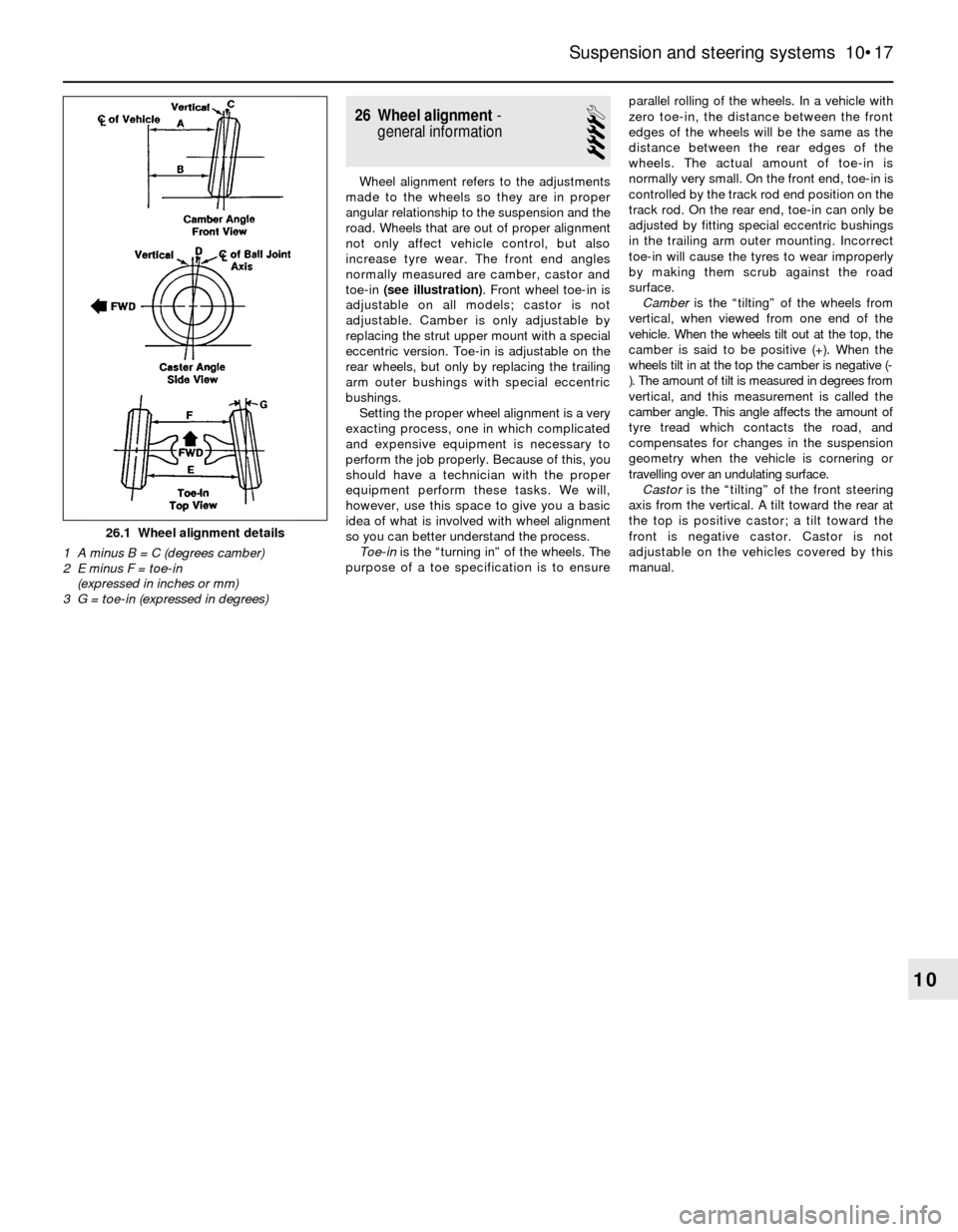
increase tyre wear. The front end angles
normally measured are camber, castor and
toe-in (see illustration). Front wheel toe-in is
adjustable on all models; castor is not
adjustable. Camber is only adjustable by
replacing the strut upper mount with a special
eccentric version. Toe-in is adjustable on the
rear wheels, but only by replacing the trailing
arm outer bushings with special eccentric
bushings.
Setting the proper wheel alignment is a very
exacting process, one in which complicated
and expensive equipment is necessary to
perform the job properly. Because of this, you
should have a technician with the proper
equipment perform these tasks. We will,
however, use this space to give you a basic
idea of what is involved with wheel alignment
so you can better understand the process.
Toe-inis the “turning in” of the wheels. The
purpose of a toe specification is to ensureparallel rolling of the wheels. In a vehicle with
zero toe-in, the distance between the front
edges of the wheels will be the same as the
distance between the rear edges of the
wheels. The actual amount of toe-in is
normally very small. On the front end, toe-in is
controlled by the track rod end position on the
track rod. On the rear end, toe-in can only be
adjusted by fitting special eccentric bushings
in the trailing arm outer mounting. Incorrect
toe-in will cause the tyres to wear improperly
by making them scrub against the road
surface.
Camberis the “tilting” of the wheels from
vertical, when viewed from one end of the
vehicle. When the wheels tilt out at the top, the
camber is said to be positive (+). When the
wheels tilt in at the top the camber is negative (-
). The amount of tilt is measured in degrees from
vertical, and this measurement is called the
camber angle. This angle affects the amount of
tyre tread which contacts the road, and
compensates for changes in the suspension
geometry when the vehicle is cornering or
travelling over an undulating surface.
Castoris the “tilting” of the front steering
axis from the vertical. A tilt toward the rear at
the top is positive castor; a tilt toward the
front is negative castor. Castor is not
adjustable on the vehicles covered by this
manual.
Suspension and steering systems 10•17
10
26.1 Wheel alignment details
1 A minus B = C (degrees camber)
2 E minus F = toe-in
(expressed in inches or mm)
3 G = toe-in (expressed in degrees)
Page 176 of 228
12Refitting is a reversal of removal. When
fitting the motor, if necessary plug in the
connector and run the motor briefly until it is
in the “neutral” (wiper parked) position.
17 Heated rear window-
check and repair
2
1The heated rear window consists of a
number of horizontal elements on the glass
surface.
2Small breaks in the element can be repaired
without removing the rear window.
Check
3Switch on the ignition and the heated rear
window.
4Place the positive lead of a voltmeter to the
heater element nearest to the incoming power
source.
5Wrap a piece of aluminium foil around the
negative lead of the voltmeter on the positive
side of the suspected broken element, and
slide it slowly towards the negative side.
Watch the voltmeter needle - when it moves
from zero, you have located the break.
Repair
6Repair the break in the line using a repair kit
recommended specifically for this purpose,
such as BMW repair kit No. 81 22 9 (or
equivalent). Included in this kit is plastic
conductive epoxy. The following paragraphs
give general instructions for this type of repair;
follow the instructions supplied with the repair
kit if they are different.
7Prior to repairing a break, switch off the
circuit and allow it to cool down for a few
minutes.
8Lightly buff the element area with fine steel
wool, then clean it thoroughly.
9Use masking tape to mask off the area of
repair, leaving a slit to which the epoxy can be
applied.
10Mix the epoxy thoroughly, according to
the instructions on the package.
11Apply the epoxy material to the slit in the
masking tape, overlapping the undamaged
area about 20 mm on each end.12Allow the repair to cure for 24 hours
before removing the tape and using the
heated rear window.
18 Supplemental Restraint
System (SRS)- general
information
Later models are equipped with a
Supplemental Restraint System (SRS),
incorporating an airbag. This system is
designed to protect the driver from serious
injury in the event of a head-on or frontal
collision. It consists of an airbag module in the
centre of the steering wheel, two crash
sensors mounted on the front inner wing
panels, and a crash safety switch located
inside the passenger compartment.
The airbag module contains a housing
incorporating the airbag and the inflator units.
The inflator assembly is mounted on the back
of the housing over a hole through which gas
is expelled, inflating the bag almost instanta-
neously when an electrical signal is sent from
the system. This signal is carried by a wire
which is specially wound with several turns,
so the signal will be transmitted regardless of
the steering wheel position.
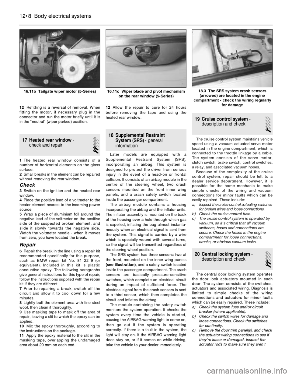
The SRS system has three sensors: two at
the front, mounted on the inner wing panels
(see illustration), and a safety switch located
inside the passenger compartment. The crash
sensors are basically pressure-sensitive
switches, which complete an electrical circuit
during an impact of sufficient force. The
electrical signal from the crash sensors is sent
to a third sensor, which then completes the
circuit and inflates the airbag.
The module containing the safety switch
monitors the system operation. It checks the
system every time the vehicle is started,
causing the AIRBAG warning light to come on,
then go out if the system is operating
correctly. If there is a fault in the system, the
light will stay on. If the AIRBAG warning light
does stay on, or if it comes on while driving,
take the vehicle to your dealer immediately.
19 Cruise control system-
description and check
1
The cruise control system maintains vehicle
speed using a vacuum-actuated servo motor
located in the engine compartment, which is
connected to the throttle linkage by a cable.
The system consists of the servo motor,
clutch switch, brake switch, control switches,
a relay, and associated vacuum hoses.
Because of the complexity of the cruise
control system, repair should be left to a
dealer service department. However, it is
possible for the home mechanic to make
simple checks of the wiring and vacuum
connections for minor faults which can be
easily repaired. These include:
a) Inspect the cruise control actuating switches
for broken wires and loose connections.
b) Check the cruise control fuse.
c) The cruise control system is operated by
vacuum, so it’s critical that all vacuum
switches, hoses and connections are
secure. Check the hoses in the engine
compartment for loose connections,
cracks, or obvious vacuum leaks.
20 Central locking system-
description and check
2
The central door locking system operates
the door lock actuators mounted in each
door. The system consists of the switches,
actuators and associated wiring. Diagnosis is
limited to simple checks of the wiring
connections and actuators for minor faults
which can be easily repaired. These include:
a) Check the system fuse and/or circuit
breaker (where applicable).
b) Check the switch wires for damage and
loose connections. Check the switches
for continuity.
c) Remove the door trim panel(s), and check
the actuator wiring connections to see if
they’re loose or damaged. Inspect the
actuator rods to make sure they aren’t
12•8 Body electrical systems
18.3 The SRS system crash sensors
(arrowed) are located in the engine
compartment - check the wiring regularly
for damage16.11b Tailgate wiper motor (5-Series)16.11c Wiper blade and pivot mechanism
on the rear window (5-Series)