flat BMW 3 SERIES 1990 E30 Workshop Manual
[x] Cancel search | Manufacturer: BMW, Model Year: 1990, Model line: 3 SERIES, Model: BMW 3 SERIES 1990 E30Pages: 228, PDF Size: 7.04 MB
Page 9 of 228
0•9Roadside Repairs
When jump-starting a car using a
booster battery, observe the following
precautions:
4Before connecting the booster
battery, make sure that the ignition is
switched off.
4Ensure that all electrical equipment
(lights, heater, wipers, etc) is
switched off.
4Make sure that the booster battery is
the same voltage as the discharged
one in the vehicle.
4If the battery is being jump-started
from the battery in another vehicle,
the two vehcles MUST NOT TOUCH
each other.
4Make sure that the transmission is in
neutral (or PARK, in the case of
automatic transmission).
Jump starting will get you out
of trouble, but you must correct
whatever made the battery go
flat in the first place. There are
three possibilities:
1The battery has been drained by
repeated attempts to start, or by
leaving the lights on.
2The charging system is not working
properly (alternator drivebelt slack
or broken, alternator wiring fault or
alternator itself faulty).
3The battery itself is at fault
(electrolyte low, or battery worn out).
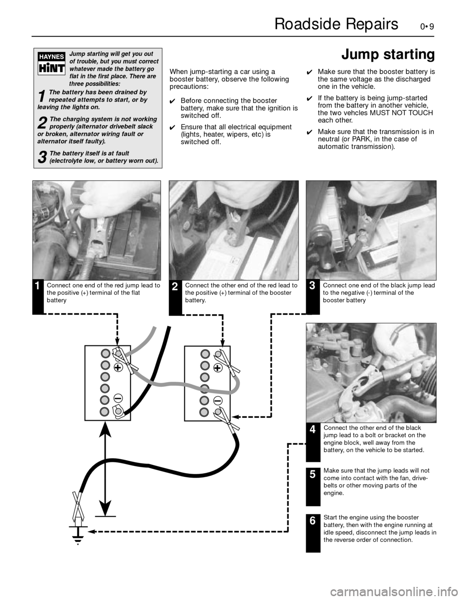
Connect one end of the red jump lead to
the positive (+) terminal of the flat
batteryConnect the other end of the red lead to
the positive (+) terminal of the booster
battery.Connect one end of the black jump lead
to the negative (-) terminal of the
booster battery
Connect the other end of the black
jump lead to a bolt or bracket on the
engine block, well away from the
battery, on the vehicle to be started.
123
4
Make sure that the jump leads will not
come into contact with the fan, drive-
belts or other moving parts of the
engine.5
Start the engine using the booster
battery, then with the engine running at
idle speed, disconnect the jump leads in
the reverse order of connection.6
Jump starting
Page 19 of 228
inhibitors wear out, so it must be renewed at
the specified intervals.
Brake and clutch fluid
Warning: Brake fluid can harm
your eyes and damage painted
surfaces, so use extreme caution
when handling or pouring it. Do
not use brake fluid that has been standing
open or is more than one year old. Brake
fluid absorbs moisture from the air, which
can cause a dangerous loss of brake
effectiveness. Use only the specified type
of brake fluid. Mixing different types (such
as DOT 3 or 4 and DOT 5) can cause brake
failure.
14The brake master cylinder is mounted at
the left rear corner of the engine
compartment. The clutch fluid reservoir
(manual transmission models) is mounted on
the right-hand side.
15To check the clutch fluid level, observe
the level through the translucent reservoir.
The level should be at or near the step
moulded into the reservoir. If the level is low,
remove the reservoir cap to add the specified
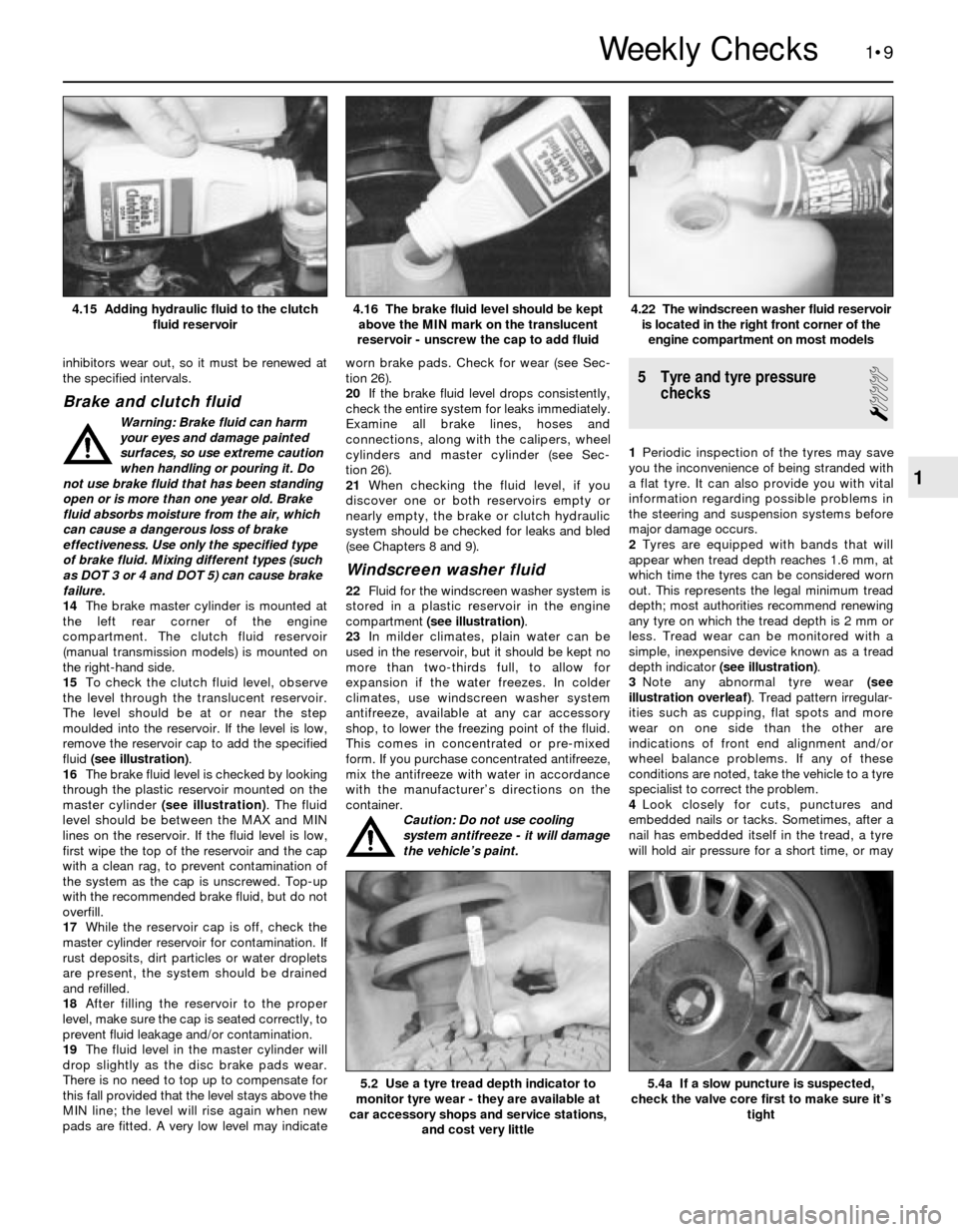
fluid (see illustration).
16The brake fluid level is checked by looking
through the plastic reservoir mounted on the
master cylinder (see illustration). The fluid
level should be between the MAX and MIN
lines on the reservoir. If the fluid level is low,
first wipe the top of the reservoir and the cap
with a clean rag, to prevent contamination of
the system as the cap is unscrewed. Top-up
with the recommended brake fluid, but do not
overfill.
17While the reservoir cap is off, check the
master cylinder reservoir for contamination. If
rust deposits, dirt particles or water droplets
are present, the system should be drained
and refilled.
18After filling the reservoir to the proper
level, make sure the cap is seated correctly, to
prevent fluid leakage and/or contamination.
19The fluid level in the master cylinder will
drop slightly as the disc brake pads wear.
There is no need to top up to compensate for
this fall provided that the level stays above the
MIN line; the level will rise again when new
pads are fitted. A very low level may indicateworn brake pads. Check for wear (see Sec-
tion 26).
20If the brake fluid level drops consistently,
check the entire system for leaks immediately.
Examine all brake lines, hoses and
connections, along with the calipers, wheel
cylinders and master cylinder (see Sec-
tion 26).
21When checking the fluid level, if you
discover one or both reservoirs empty or
nearly empty, the brake or clutch hydraulic
system should be checked for leaks and bled
(see Chapters 8 and 9).
Windscreen washer fluid
22Fluid for the windscreen washer system is
stored in a plastic reservoir in the engine
compartment (see illustration).
23In milder climates, plain water can be
used in the reservoir, but it should be kept no
more than two-thirds full, to allow for
expansion if the water freezes. In colder
climates, use windscreen washer system
antifreeze, available at any car accessory
shop, to lower the freezing point of the fluid.
This comes in concentrated or pre-mixed
form. If you purchase concentrated antifreeze,
mix the antifreeze with water in accordance
with the manufacturer’s directions on the
container.
Caution: Do not use cooling
system antifreeze - it will damage
the vehicle’s paint.
5 Tyre and tyre pressure
checks
1
1Periodic inspection of the tyres may save
you the inconvenience of being stranded with
a flat tyre. It can also provide you with vital
information regarding possible problems in
the steering and suspension systems before
major damage occurs.
2Tyres are equipped with bands that will
appear when tread depth reaches 1.6 mm, at
which time the tyres can be considered worn
out. This represents the legal minimum tread
depth; most authorities recommend renewing
any tyre on which the tread depth is 2 mm or
less. Tread wear can be monitored with a
simple, inexpensive device known as a tread
depth indicator (see illustration).
3Note any abnormal tyre wear (see
illustration overleaf). Tread pattern irregular-
ities such as cupping, flat spots and more
wear on one side than the other are
indications of front end alignment and/or
wheel balance problems. If any of these
conditions are noted, take the vehicle to a tyre
specialist to correct the problem.
4Look closely for cuts, punctures and
embedded nails or tacks. Sometimes, after a
nail has embedded itself in the tread, a tyre
will hold air pressure for a short time, or may
1•9
4.22 The windscreen washer fluid reservoir
is located in the right front corner of the
engine compartment on most models4.16 The brake fluid level should be kept
above the MIN mark on the translucent
reservoir - unscrew the cap to add fluid4.15 Adding hydraulic fluid to the clutch
fluid reservoir
5.4a If a slow puncture is suspected,
check the valve core first to make sure it’s
tight5.2 Use a tyre tread depth indicator to
monitor tyre wear - they are available at
car accessory shops and service stations,
and cost very little
1
Weekly Checks
Page 20 of 228
leak down very slowly. If a slow puncture
persists, check the valve stem core to make
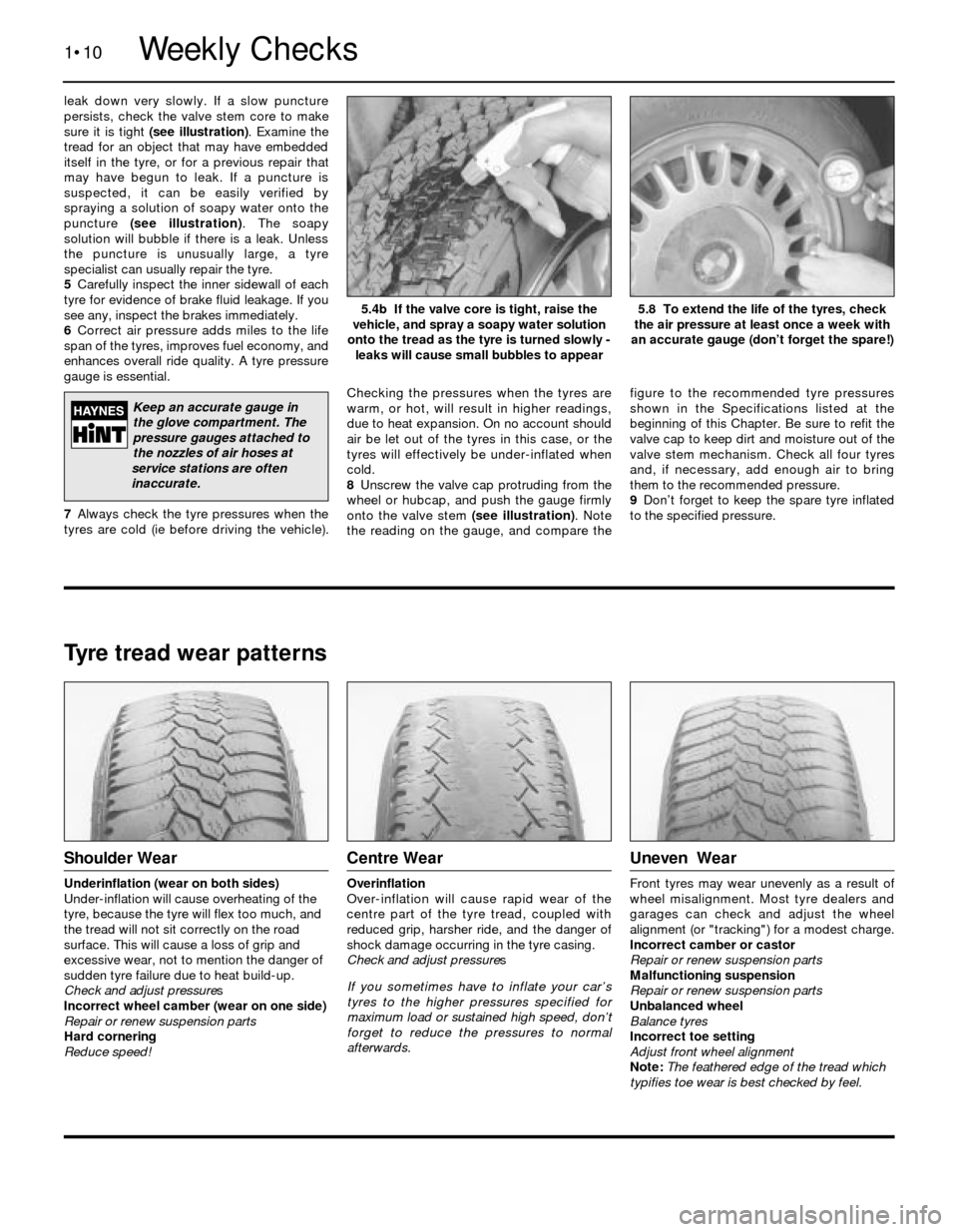
sure it is tight (see illustration). Examine the
tread for an object that may have embedded
itself in the tyre, or for a previous repair that
may have begun to leak. If a puncture is
suspected, it can be easily verified by
spraying a solution of soapy water onto the
puncture (see illustration). The soapy
solution will bubble if there is a leak. Unless
the puncture is unusually large, a tyre
specialist can usually repair the tyre.
5Carefully inspect the inner sidewall of each
tyre for evidence of brake fluid leakage. If you
see any, inspect the brakes immediately.
6Correct air pressure adds miles to the life
span of the tyres, improves fuel economy, and
enhances overall ride quality. A tyre pressure
gauge is essential.
7Always check the tyre pressures when the
tyres are cold (ie before driving the vehicle).Checking the pressures when the tyres are
warm, or hot, will result in higher readings,
due to heat expansion. On no account should
air be let out of the tyres in this case, or the
tyres will effectively be under-inflated when
cold.
8Unscrew the valve cap protruding from the
wheel or hubcap, and push the gauge firmly
onto the valve stem (see illustration). Note
the reading on the gauge, and compare thefigure to the recommended tyre pressures
shown in the Specifications listed at the
beginning of this Chapter. Be sure to refit the
valve cap to keep dirt and moisture out of the
valve stem mechanism. Check all four tyres
and, if necessary, add enough air to bring
them to the recommended pressure.
9Don’t forget to keep the spare tyre inflated
to the specified pressure.
1•10
5.8 To extend the life of the tyres, check
the air pressure at least once a week with
an accurate gauge (don’t forget the spare!)5.4b If the valve core is tight, raise the
vehicle, and spray a soapy water solution
onto the tread as the tyre is turned slowly -
leaks will cause small bubbles to appear
Tyre tread wear patterns
Shoulder Wear
Underinflation (wear on both sides)
Under-inflation will cause overheating of the
tyre, because the tyre will flex too much, and
the tread will not sit correctly on the road
surface. This will cause a loss of grip and
excessive wear, not to mention the danger of
sudden tyre failure due to heat build-up.
Check and adjust pressures
Incorrect wheel camber (wear on one side)
Repair or renew suspension parts
Hard cornering
Reduce speed!
Centre Wear
Overinflation
Over-inflation will cause rapid wear of the
centre part of the tyre tread, coupled with
reduced grip, harsher ride, and the danger of
shock damage occurring in the tyre casing.
Check and adjust pressures
If you sometimes have to inflate your car’s
tyres to the higher pressures specified for
maximum load or sustained high speed, don’t
forget to reduce the pressures to normal
afterwards.
Uneven Wear
Front tyres may wear unevenly as a result of
wheel misalignment. Most tyre dealers and
garages can check and adjust the wheel
alignment (or "tracking") for a modest charge.
Incorrect camber or castor
Repair or renew suspension parts
Malfunctioning suspension
Repair or renew suspension parts
Unbalanced wheel
Balance tyres
Incorrect toe setting
Adjust front wheel alignment
Note: The feathered edge of the tread which
typifies toe wear is best checked by feel.
Weekly Checks
Keep an accurate gauge in
the glove compartment. The
pressure gauges attached to
the nozzles of air hoses at
service stations are often
inaccurate.
Page 61 of 228
otherwise a small brush or even a bicycle tyre
pump will work). The idea is to prevent dirt
from getting into the cylinders as the
compression check is being done.
3Remove all the spark plugs from the engine
(see Chapter 1).
4Block the throttle wide open, or have an
assistant hold the throttle pedal down.
5On carburettor models, disconnect the LT
lead from the coil. On fuel injection models,
disable the fuel pump and ignition circuit by
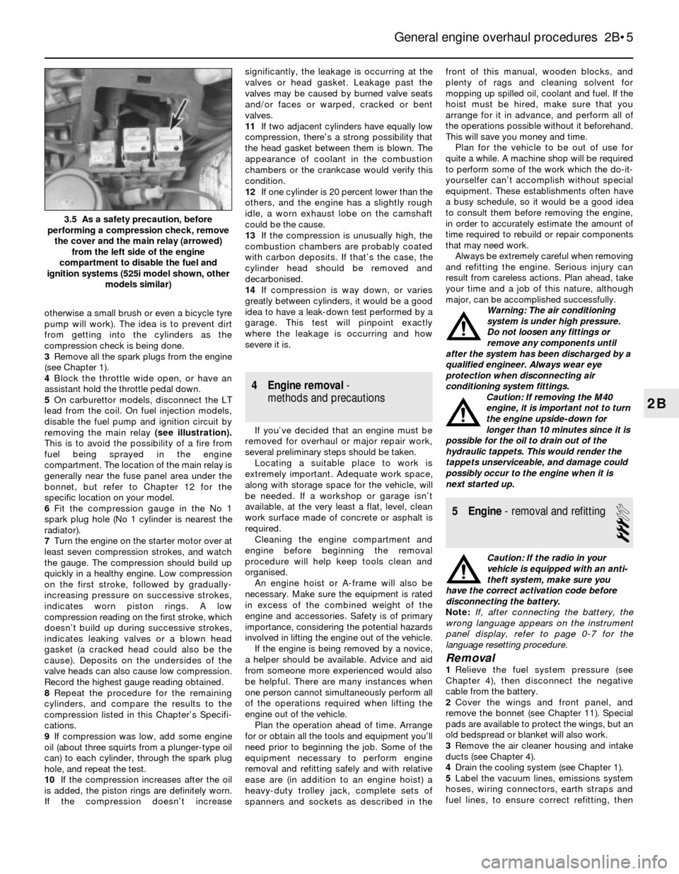
removing the main relay(see illustration).
This is to avoid the possibility of a fire from
fuel being sprayed in the engine
compartment. The location of the main relay is
generally near the fuse panel area under the
bonnet, but refer to Chapter 12 for the
specific location on your model.
6Fit the compression gauge in the No 1
spark plug hole (No 1 cylinder is nearest the
radiator).
7Turn the engine on the starter motor over at
least seven compression strokes, and watch
the gauge. The compression should build up
quickly in a healthy engine. Low compression
on the first stroke, followed by gradually-
increasing pressure on successive strokes,
indicates worn piston rings. A low
compression reading on the first stroke, which
doesn’t build up during successive strokes,
indicates leaking valves or a blown head
gasket (a cracked head could also be the
cause). Deposits on the undersides of the
valve heads can also cause low compression.
Record the highest gauge reading obtained.
8Repeat the procedure for the remaining
cylinders, and compare the results to the
compression listed in this Chapter’s Specifi-
cations.
9If compression was low, add some engine
oil (about three squirts from a plunger-type oil
can) to each cylinder, through the spark plug
hole, and repeat the test.
10If the compression increases after the oil
is added, the piston rings are definitely worn.
If the compression doesn’t increasesignificantly, the leakage is occurring at the
valves or head gasket. Leakage past the
valves may be caused by burned valve seats
and/or faces or warped, cracked or bent
valves.
11If two adjacent cylinders have equally low
compression, there’s a strong possibility that
the head gasket between them is blown. The
appearance of coolant in the combustion
chambers or the crankcase would verify this
condition.
12If one cylinder is 20 percent lower than the
others, and the engine has a slightly rough
idle, a worn exhaust lobe on the camshaft
could be the cause.
13If the compression is unusually high, the
combustion chambers are probably coated
with carbon deposits. If that’s the case, the
cylinder head should be removed and
decarbonised.
14If compression is way down, or varies
greatly between cylinders, it would be a good
idea to have a leak-down test performed by a
garage. This test will pinpoint exactly
where the leakage is occurring and how
severe it is.
4 Engine removal-
methods and precautions
If you’ve decided that an engine must be
removed for overhaul or major repair work,
several preliminary steps should be taken.
Locating a suitable place to work is
extremely important. Adequate work space,
along with storage space for the vehicle, will
be needed. If a workshop or garage isn’t
available, at the very least a flat, level, clean
work surface made of concrete or asphalt is
required.
Cleaning the engine compartment and
engine before beginning the removal
procedure will help keep tools clean and
organised.
An engine hoist or A-frame will also be
necessary. Make sure the equipment is rated
in excess of the combined weight of the
engine and accessories. Safety is of primary
importance, considering the potential hazards
involved in lifting the engine out of the vehicle.
If the engine is being removed by a novice,
a helper should be available. Advice and aid
from someone more experienced would also
be helpful. There are many instances when
one person cannot simultaneously perform all
of the operations required when lifting the
engine out of the vehicle.
Plan the operation ahead of time. Arrange
for or obtain all the tools and equipment you’ll
need prior to beginning the job. Some of the
equipment necessary to perform engine
removal and refitting safely and with relative
ease are (in addition to an engine hoist) a
heavy-duty trolley jack, complete sets of
spanners and sockets as described in thefront of this manual, wooden blocks, and
plenty of rags and cleaning solvent for
mopping up spilled oil, coolant and fuel. If the
hoist must be hired, make sure that you
arrange for it in advance, and perform all of
the operations possible without it beforehand.
This will save you money and time.
Plan for the vehicle to be out of use for
quite a while. A machine shop will be required
to perform some of the work which the do-it-
yourselfer can’t accomplish without special
equipment. These establishments often have
a busy schedule, so it would be a good idea
to consult them before removing the engine,
in order to accurately estimate the amount of
time required to rebuild or repair components
that may need work.
Always be extremely careful when removing
and refitting the engine. Serious injury can
result from careless actions. Plan ahead, take
your time and a job of this nature, although
major, can be accomplished successfully.
Warning: The air conditioning
system is under high pressure.
Do not loosen any fittings or
remove any components until
after the system has been discharged by a
qualified engineer. Always wear eye
protection when disconnecting air
conditioning system fittings.
Caution: If removing the M40
engine, it is important not to turn
the engine upside-down for
longer than 10 minutes since it is
possible for the oil to drain out of the
hydraulic tappets. This would render the
tappets unserviceable, and damage could
possibly occur to the engine when it is
next started up.
5 Engine- removal and refitting
3
Caution: If the radio in your
vehicle is equipped with an anti-
theft system, make sure you
have the correct activation code before
disconnecting the battery.
Note: If, after connecting the battery, the
wrong language appears on the instrument
panel display, refer to page 0-7 for the
language resetting procedure.
Removal1Relieve the fuel system pressure (see
Chapter 4), then disconnect the negative
cable from the battery.
2Cover the wings and front panel, and
remove the bonnet (see Chapter 11). Special
pads are available to protect the wings, but an
old bedspread or blanket will also work.
3Remove the air cleaner housing and intake
ducts (see Chapter 4).
4Drain the cooling system (see Chapter 1).
5Label the vacuum lines, emissions system
hoses, wiring connectors, earth straps and
fuel lines, to ensure correct refitting, then
General engine overhaul procedures 2B•5
3.5 As a safety precaution, before
performing a compression check, remove
the cover and the main relay (arrowed)
from the left side of the engine
compartment to disable the fuel and
ignition systems (525i model shown, other
models similar)
2B
Page 62 of 228
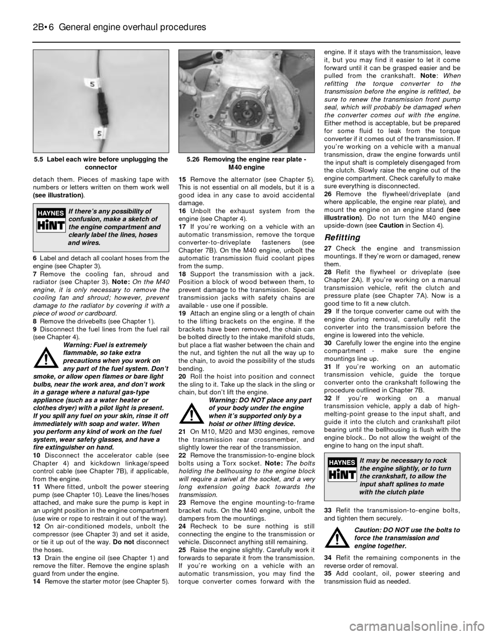
detach them. Pieces of masking tape with
numbers or letters written on them work well
(see illustration).
6Label and detach all coolant hoses from the
engine (see Chapter 3).
7Remove the cooling fan, shroud and
radiator (see Chapter 3). Note:On the M40
engine, it is only necessary to remove the
cooling fan and shroud; however, prevent
damage to the radiator by covering it with a
piece of wood or cardboard.
8Remove the drivebelts (see Chapter 1).
9Disconnect the fuel lines from the fuel rail
(see Chapter 4).
Warning: Fuel is extremely
flammable, so take extra
precautions when you work on
any part of the fuel system. Don’t
smoke, or allow open flames or bare light
bulbs, near the work area, and don’t work
in a garage where a natural gas-type
appliance (such as a water heater or
clothes dryer) with a pilot light is present.
If you spill any fuel on your skin, rinse it off
immediately with soap and water. When
you perform any kind of work on the fuel
system, wear safety glasses, and have a
fire extinguisher on hand.
10Disconnect the accelerator cable (see
Chapter 4) and kickdown linkage/speed
control cable (see Chapter 7B), if applicable,
from the engine.
11Where fitted, unbolt the power steering
pump (see Chapter 10). Leave the lines/hoses
attached, and make sure the pump is kept in
an upright position in the engine compartment
(use wire or rope to restrain it out of the way).
12On air-conditioned models, unbolt the
compressor (see Chapter 3) and set it aside,
or tie it up out of the way. Do not disconnect
the hoses.
13Drain the engine oil (see Chapter 1) and
remove the filter. Remove the engine splash
guard from under the engine.
14Remove the starter motor (see Chapter 5).15Remove the alternator (see Chapter 5).
This is not essential on all models, but it is a
good idea in any case to avoid accidental
damage.
16Unbolt the exhaust system from the
engine (see Chapter 4).
17If you’re working on a vehicle with an
automatic transmission, remove the torque
converter-to-driveplate fasteners (see
Chapter 7B). On the M40 engine, unbolt the
automatic transmission fluid coolant pipes
from the sump.
18Support the transmission with a jack.
Position a block of wood between them, to
prevent damage to the transmission. Special
transmission jacks with safety chains are
available - use one if possible.
19Attach an engine sling or a length of chain
to the lifting brackets on the engine. If the
brackets have been removed, the chain can
be bolted directly to the intake manifold studs,
but place a flat washer between the chain and
the nut, and tighten the nut all the way up to
the chain, to avoid the possibility of the studs
bending.
20Roll the hoist into position and connect
the sling to it. Take up the slack in the sling or
chain, but don’t lift the engine.
Warning: DO NOT place any part
of your body under the engine
when it’s supported only by a
hoist or other lifting device.
21On M10, M20 and M30 engines, remove
the transmission rear crossmember, and
slightly lower the rear of the transmission.
22Remove the transmission-to-engine block
bolts using a Torx socket. Note:The bolts
holding the bellhousing to the engine block
will require a swivel at the socket, and a very
long extension going back towards the
transmission.
23Remove the engine mounting-to-frame
bracket nuts. On the M40 engine, unbolt the
dampers from the mountings.
24Recheck to be sure nothing is still
connecting the engine to the transmission or
vehicle. Disconnect anything still remaining.
25Raise the engine slightly. Carefully work it
forwards to separate it from the transmission.
If you’re working on a vehicle with an
automatic transmission, you may find the
torque converter comes forward with theengine. If it stays with the transmission, leave
it, but you may find it easier to let it come
forward until it can be grasped easier and be
pulled from the crankshaft. Note:When
refitting the torque converter to the
transmission before the engine is refitted, be
sure to renew the transmission front pump
seal, which will probably be damaged when
the converter comes out with the engine.
Either method is acceptable, but be prepared
for some fluid to leak from the torque
converter if it comes out of the transmission. If
you’re working on a vehicle with a manual
transmission, draw the engine forwards until
the input shaft is completely disengaged from
the clutch. Slowly raise the engine out of the
engine compartment. Check carefully to make
sure everything is disconnected.
26Remove the flywheel/driveplate (and
where applicable, the engine rear plate), and
mount the engine on an engine stand (see
illustration). Do not turn the M40 engine
upside-down (see Cautionin Section 4).
Refitting
27Check the engine and transmission
mountings. If they’re worn or damaged, renew
them.
28Refit the flywheel or driveplate (see
Chapter 2A). If you’re working on a manual
transmission vehicle, refit the clutch and
pressure plate (see Chapter 7A). Now is a
good time to fit a new clutch.
29If the torque converter came out with the
engine during removal, carefully refit the
converter into the transmission before the
engine is lowered into the vehicle.
30Carefully lower the engine into the engine
compartment - make sure the engine
mountings line up.
31If you’re working on an automatic
transmission vehicle, guide the torque
converter onto the crankshaft following the
procedure outlined in Chapter 7B.
32If you’re working on a manual
transmission vehicle, apply a dab of high-
melting-point grease to the input shaft, and
guide it into the clutch and crankshaft pilot
bearing until the bellhousing is flush with the
engine block.. Do not allow the weight of the
engine to hang on the input shaft.
33Refit the transmission-to-engine bolts,
and tighten them securely.
Caution: DO NOT use the bolts to
force the transmission and
engine together.
34Refit the remaining components in the
reverse order of removal.
35Add coolant, oil, power steering and
transmission fluid as needed.
2B•6 General engine overhaul procedures
5.26 Removing the engine rear plate -
M40 engine5.5 Label each wire before unplugging the
connector
If there’s any possibility of
confusion, make a sketch of
the engine compartment and
clearly label the lines, hoses
and wires.
It may be necessary to rock
the engine slightly, or to turn
the crankshaft, to allow the
input shaft splines to mate
with the clutch plate
Page 67 of 228
that they’re suitable for use in a rebuilt engine
(take the springs to a machine shop for this
check).
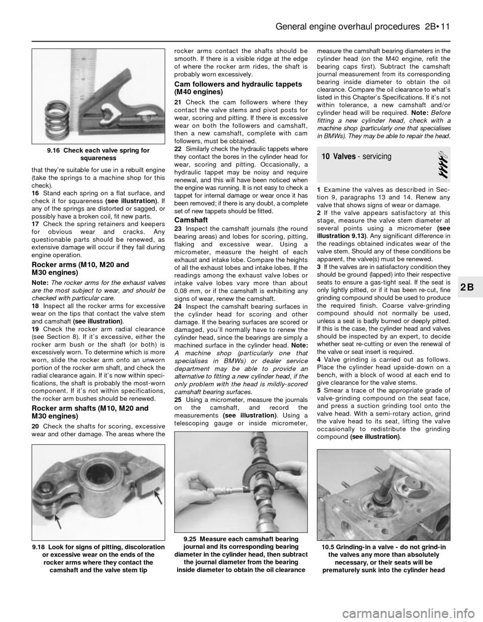
16Stand each spring on a flat surface, and
check it for squareness (see illustration). If
any of the springs are distorted or sagged, or
possibly have a broken coil, fit new parts.
17Check the spring retainers and keepers
for obvious wear and cracks. Any
questionable parts should be renewed, as
extensive damage will occur if they fail during
engine operation.
Rocker arms (M10, M20 and
M30 engines)
Note:The rocker arms for the exhaust valves
are the most subject to wear, and should be
checked with particular care.
18Inspect all the rocker arms for excessive
wear on the tips that contact the valve stem
and camshaft (see illustration).
19Check the rocker arm radial clearance
(see Section 8). If it’s excessive, either the
rocker arm bush or the shaft (or both) is
excessively worn. To determine which is more
worn, slide the rocker arm onto an unworn
portion of the rocker arm shaft, and check the
radial clearance again. If it’s now within speci-
fications, the shaft is probably the most-worn
component. If it’s not within specifications,
the rocker arm bushes should be renewed.
Rocker arm shafts (M10, M20 and
M30 engines)
20Check the shafts for scoring, excessive
wear and other damage. The areas where therocker arms contact the shafts should be
smooth. If there is a visible ridge at the edge
of where the rocker arm rides, the shaft is
probably worn excessively.
Cam followers and hydraulic tappets
(M40 engines)
21Check the cam followers where they
contact the valve stems and pivot posts for
wear, scoring and pitting. If there is excessive
wear on both the followers and camshaft,
then a new camshaft, complete with cam
followers, must be obtained.
22Similarly check the hydraulic tappets where
they contact the bores in the cylinder head for
wear, scoring and pitting. Occasionally, a
hydraulic tappet may be noisy and require
renewal, and this will have been noticed when
the engine was running. It is not easy to check a
tappet for internal damage or wear once it has
been removed; if there is any doubt, a complete
set of new tappets should be fitted.
Camshaft
23Inspect the camshaft journals (the round
bearing areas) and lobes for scoring, pitting,
flaking and excessive wear. Using a
micrometer, measure the height of each
exhaust and intake lobe. Compare the heights
of all the exhaust lobes and intake lobes. If the
readings among the exhaust valve lobes or
intake valve lobes vary more than about
0.08 mm, or if the camshaft is exhibiting any
signs of wear, renew the camshaft.
24Inspect the camshaft bearing surfaces in
the cylinder head for scoring and other
damage. If the bearing surfaces are scored or
damaged, you’ll normally have to renew the
cylinder head, since the bearings are simply a
machined surface in the cylinder head. Note:
A machine shop (particularly one that
specialises in BMWs) or dealer service
department may be able to provide an
alternative to fitting a new cylinder head, if the
only problem with the head is mildly-scored
camshaft bearing surfaces.
25Using a micrometer, measure the journals
on the camshaft, and record the
measurements (see illustration). Using a
telescoping gauge or inside micrometer,measure the camshaft bearing diameters in the
cylinder head (on the M40 engine, refit the
bearing caps first). Subtract the camshaft
journal measurement from its corresponding
bearing inside diameter to obtain the oil
clearance. Compare the oil clearance to what’s
listed in this Chapter’s Specifications. If it’s not
within tolerance, a new camshaft and/or
cylinder head will be required. Note:Before
fitting a new cylinder head, check with a
machine shop (particularly one that specialises
in BMWs). They may be able to repair the head.
10 Valves- servicing
4
1Examine the valves as described in Sec-
tion 9, paragraphs 13 and 14. Renew any
valve that shows signs of wear or damage.
2If the valve appears satisfactory at this
stage, measure the valve stem diameter at
several points using a micrometer (see
illustration 9.13). Any significant difference in
the readings obtained indicates wear of the
valve stem. Should any of these conditions be
apparent, the valve(s) must be renewed.
3If the valves are in satisfactory condition they
should be ground (lapped) into their respective
seats to ensure a gas-tight seal. If the seat is
only lightly pitted, or if it has been re-cut, fine
grinding compound should be used to produce
the required finish. Coarse valve-grinding
compound should not normally be used,
unless a seat is badly burned or deeply pitted.
If this is the case, the cylinder head and valves
should be inspected by an expert, to decide
whether seat re-cutting or even the renewal of
the valve or seat insert is required.
4Valve grinding is carried out as follows.
Place the cylinder head upside-down on a
bench, with a block of wood at each end to
give clearance for the valve stems.
5Smear a trace of the appropriate grade of
valve-grinding compound on the seat face,
and press a suction grinding tool onto the
valve head. With a semi-rotary action, grind
the valve head to its seat, lifting the valve
occasionally to redistribute the grinding
compound (see illustration).
General engine overhaul procedures 2B•11
9.25 Measure each camshaft bearing
journal and its corresponding bearing
diameter in the cylinder head, then subtract
the journal diameter from the bearing
inside diameter to obtain the oil clearance9.18 Look for signs of pitting, discoloration
or excessive wear on the ends of the
rocker arms where they contact the
camshaft and the valve stem tip10.5 Grinding-in a valve - do not grind-in
the valves any more than absolutely
necessary, or their seats will be
prematurely sunk into the cylinder head
2B
9.16 Check each valve spring for
squareness
Page 103 of 228
8Check the fuel system pressure (see
Section 3).
9If these checks do not locate the problem,
take the vehicle to a BMW dealer, who will be
able to read the fault codes stored in the ECU,
using special equipment.
16 Airflow meter- check,
removal and refitting
2
Check (L-Jetronic systems)
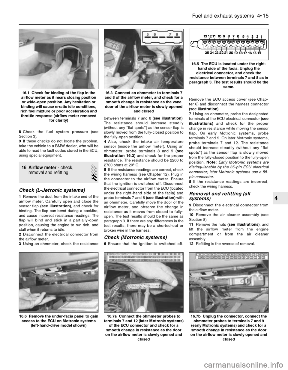
1Remove the duct from the intake end of the
airflow meter. Carefully open and close the
sensor flap (see illustration), and check for
binding. The flap can bend during a backfire,
and cause incorrect resistance readings. The
flap will bind and stick in a partially-open
position, causing the engine to run rich, and
stall when it returns to idle.
2Disconnect the electrical connector from
the airflow meter.
3Using an ohmmeter, check the resistancebetween terminals 7 and 8 (see illustration).
The resistance should increase steadily
(without any “flat spots”) as the sensor flap is
slowly moved from the fully-closed position to
the fully-open position.
4Also, check the intake air temperature
sensor (inside the airflow meter). Using an
ohmmeter, probe terminals 8 and 9 (see
illustration 16.3)and check for the proper
resistance. The resistance should be 2200 to
2700 ohms at 20º C.
5If the resistance readings are correct, check
the wiring harness (see Chapter 12). Plug in
the connector to the airflow meter. Ensure
that the ignition is switched off. Disconnect
the electrical connector from the ECU (located
under the right-hand side of the facia) and
probe terminals 7 and 8 (see illustration)with
an ohmmeter. Carefully move the door of the
airflow meter, and observe the change in
resistance as it moves from closed to fully-
open. The test results should be the same as
paragraph 3. If there are any differences in the
test results, there may be a shorted-out or
broken wire in the harness.
Check (Motronic systems)
6Ensure that the ignition is switched off.Remove the ECU access cover (see Chap-
ter 6) and disconnect the harness connector
(see illustration).
7Using an ohmmeter, probe the designated
terminals of the ECU electrical connector (see
illustrations)and check for the proper
change in resistance while moving the sensor
flap. On early Motronic systems, probe
terminals 7 and 9. On later Motronic systems,
probe terminals 7 and 12. The resistance
should increase steadily (without any “flat
spots”) as the sensor flap is slowly moved
from the fully-closed position to the fully-open
position. Note: Early Motronic systems are
distinguishable by the 35-pin ECU electrical
connector; later Motronic systems use a 55-
pin connector.
8If the resistance readings are incorrect,
check the wiring harness.
Removal and refitting (all
systems)
9Disconnect the electrical connector from
the airflow meter.
10Remove the air cleaner assembly (see
Section 8).
11Remove the nuts (see illustrations), and
lift the airflow meter from the engine
compartment or from the air cleaner
assembly.
12Refitting is the reverse of removal.
Fuel and exhaust systems 4•15
16.5 The ECU is located under the right-
hand side of the facia. Unplug the
electrical connector, and check the
resistance between terminals 7 and 8 as in
paragraph 3. The test results should be the
same.
16.3 Connect an ohmmeter to terminals 7
and 8 of the airflow meter, and check for a
smooth change in resistance as the vane
door of the airflow meter is slowly opened
and closed16.1 Check for binding of the flap in the
airflow meter as it nears closing position
or wide-open position. Any hesitation or
binding will cause erratic idle conditions,
rich fuel mixture or poor acceleration and
throttle response (airflow meter removed
for clarity)
16.7b Unplug the connector, connect the
ohmmeter probes to terminals 7 and 9
(early Motronic systems) and check for a
smooth change in resistance as the door
on the airflow meter is slowly opened and
closed16.7a Connect the ohmmeter probes to
terminals 7 and 12 (later Motronic systems)
of the ECU connector and check for a
smooth change in resistance as the door
on the airflow meter is slowly opened and
closed16.6 Remove the under-facia panel to gain
access to the ECU on Motronic systems
(left-hand-drive model shown)
4
Page 117 of 228
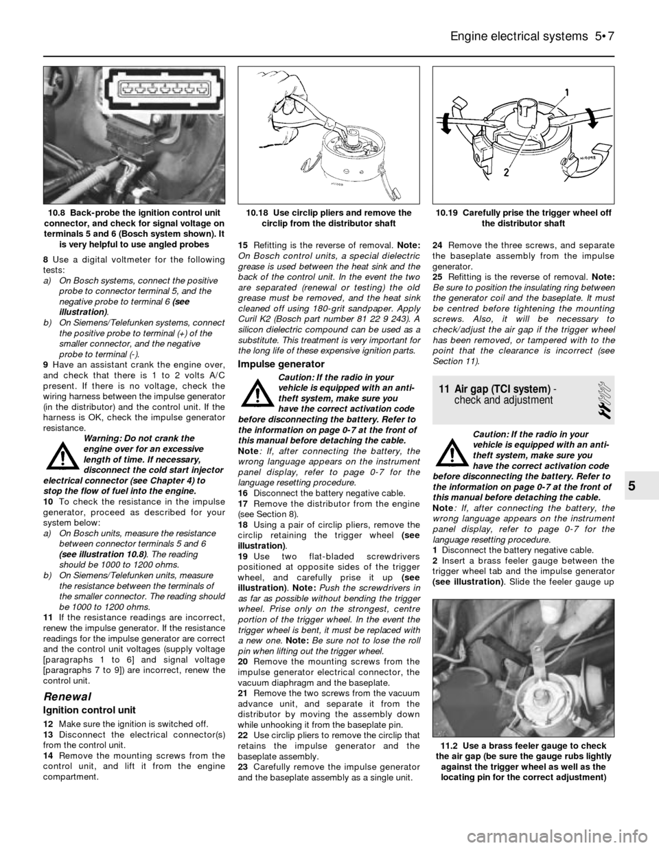
8Use a digital voltmeter for the following
tests:
a) On Bosch systems, connect the positive
probe to connector terminal 5, and the
negative probe to terminal 6 (see
illustration).
b) On Siemens/Telefunken systems, connect
the positive probe to terminal (+) of the
smaller connector, and the negative
probe to terminal (-).
9Have an assistant crank the engine over,
and check that there is 1 to 2 volts A/C
present. If there is no voltage, check the
wiring harness between the impulse generator
(in the distributor) and the control unit. If the
harness is OK, check the impulse generator
resistance.
Warning: Do not crank the
engine over for an excessive
length of time. If necessary,
disconnect the cold start injector
electrical connector (see Chapter 4) to
stop the flow of fuel into the engine.
10To check the resistance in the impulse
generator, proceed as described for your
system below:
a) On Bosch units, measure the resistance
between connector terminals 5 and 6
(see illustration 10.8). The reading
should be 1000 to 1200 ohms.
b) On Siemens/Telefunken units, measure
the resistance between the terminals of
the smaller connector. The reading should
be 1000 to 1200 ohms.
11If the resistance readings are incorrect,
renew the impulse generator. If the resistance
readings for the impulse generator are correct
and the control unit voltages (supply voltage
[paragraphs 1 to 6] and signal voltage
[paragraphs 7 to 9]) are incorrect, renew the
control unit.
Renewal
Ignition control unit
12Make sure the ignition is switched off.
13Disconnect the electrical connector(s)
from the control unit.
14Remove the mounting screws from the
control unit, and lift it from the engine
compartment.15Refitting is the reverse of removal. Note:
On Bosch control units, a special dielectric
grease is used between the heat sink and the
back of the control unit. In the event the two
are separated (renewal or testing) the old
grease must be removed, and the heat sink
cleaned off using 180-grit sandpaper. Apply
Curil K2 (Bosch part number 81 22 9 243). A
silicon dielectric compound can be used as a
substitute. This treatment is very important for
the long life of these expensive ignition parts.
Impulse generator
Caution: If the radio in your
vehicle is equipped with an anti-
theft system, make sure you
have the correct activation code
before disconnecting the battery. Refer to
the information on page 0-7 at the front of
this manual before detaching the cable.
Note: If, after connecting the battery, the
wrong language appears on the instrument
panel display, refer to page 0-7 for the
language resetting procedure.
16Disconnect the battery negative cable.
17Remove the distributor from the engine
(see Section 8).
18Using a pair of circlip pliers, remove the
circlip retaining the trigger wheel (see
illustration).
19Use two flat-bladed screwdrivers
positioned at opposite sides of the trigger
wheel, and carefully prise it up (see
illustration). Note: Push the screwdrivers in
as far as possible without bending the trigger
wheel. Prise only on the strongest, centre
portion of the trigger wheel. In the event the
trigger wheel is bent, it must be replaced with
a new one. Note:Be sure not to lose the roll
pin when lifting out the trigger wheel.
20Remove the mounting screws from the
impulse generator electrical connector, the
vacuum diaphragm and the baseplate.
21Remove the two screws from the vacuum
advance unit, and separate it from the
distributor by moving the assembly down
while unhooking it from the baseplate pin.
22Use circlip pliers to remove the circlip that
retains the impulse generator and the
baseplate assembly.
23Carefully remove the impulse generator
and the baseplate assembly as a single unit.24Remove the three screws, and separate
the baseplate assembly from the impulse
generator.
25Refitting is the reverse of removal. Note:
Be sure to position the insulating ring between
the generator coil and the baseplate. It must
be centred before tightening the mounting
screws. Also, it will be necessary to
check/adjust the air gap if the trigger wheel
has been removed, or tampered with to the
point that the clearance is incorrect (see
Section 11).
11 Air gap (TCI system)-
check and adjustment
2
Caution: If the radio in your
vehicle is equipped with an anti-
theft system, make sure you
have the correct activation code
before disconnecting the battery. Refer to
the information on page 0-7 at the front of
this manual before detaching the cable.
Note: If, after connecting the battery, the
wrong language appears on the instrument
panel display, refer to page 0-7 for the
language resetting procedure.
1Disconnect the battery negative cable.
2Insert a brass feeler gauge between the
trigger wheel tab and the impulse generator
(see illustration). Slide the feeler gauge up
Engine electrical systems 5•7
10.19 Carefully prise the trigger wheel off
the distributor shaft10.18 Use circlip pliers and remove the
circlip from the distributor shaft10.8 Back-probe the ignition control unit
connector, and check for signal voltage on
terminals 5 and 6 (Bosch system shown). It
is very helpful to use angled probes
11.2 Use a brass feeler gauge to check
the air gap (be sure the gauge rubs lightly
against the trigger wheel as well as the
locating pin for the correct adjustment)
5
Page 130 of 228
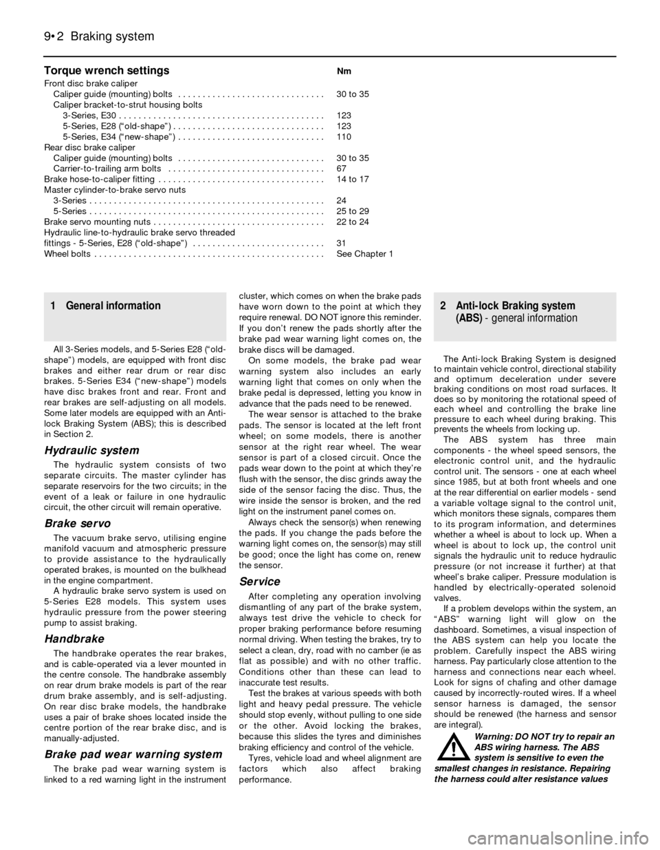
Torque wrench settingsNm
Front disc brake caliper
Caliper guide (mounting) bolts . . . . . . . . . . . . . . . . . . . . . . . . . . . . . . 30 to 35
Caliper bracket-to-strut housing bolts
3-Series, E30 . . . . . . . . . . . . . . . . . . . . . . . . . . . . . . . . . . . . . . . . . . 123
5-Series, E28 (“old-shape”) . . . . . . . . . . . . . . . . . . . . . . . . . . . . . . . 123
5-Series, E34 (“new-shape”) . . . . . . . . . . . . . . . . . . . . . . . . . . . . . . 110
Rear disc brake caliper
Caliper guide (mounting) bolts . . . . . . . . . . . . . . . . . . . . . . . . . . . . . . 30 to 35
Carrier-to-trailing arm bolts . . . . . . . . . . . . . . . . . . . . . . . . . . . . . . . . 67
Brake hose-to-caliper fitting . . . . . . . . . . . . . . . . . . . . . . . . . . . . . . . . . . 14 to 17
Master cylinder-to-brake servo nuts
3-Series . . . . . . . . . . . . . . . . . . . . . . . . . . . . . . . . . . . . . . . . . . . . . . . . 24
5-Series . . . . . . . . . . . . . . . . . . . . . . . . . . . . . . . . . . . . . . . . . . . . . . . . 25 to 29
Brake servo mounting nuts . . . . . . . . . . . . . . . . . . . . . . . . . . . . . . . . . . . 22 to 24
Hydraulic line-to-hydraulic brake servo threaded
fittings - 5-Series, E28 (“old-shape”) . . . . . . . . . . . . . . . . . . . . . . . . . . . 31
Wheel bolts . . . . . . . . . . . . . . . . . . . . . . . . . . . . . . . . . . . . . . . . . . . . . . . See Chapter 1
9•2 Braking system
1 General information
All 3-Series models, and 5-Series E28 (“old-
shape”) models, are equipped with front disc
brakes and either rear drum or rear disc
brakes. 5-Series E34 (“new-shape”) models
have disc brakes front and rear. Front and
rear brakes are self-adjusting on all models.
Some later models are equipped with an Anti-
lock Braking System (ABS); this is described
in Section 2.
Hydraulic system
The hydraulic system consists of two
separate circuits. The master cylinder has
separate reservoirs for the two circuits; in the
event of a leak or failure in one hydraulic
circuit, the other circuit will remain operative.
Brake servo
The vacuum brake servo, utilising engine
manifold vacuum and atmospheric pressure
to provide assistance to the hydraulically
operated brakes, is mounted on the bulkhead
in the engine compartment.
A hydraulic brake servo system is used on
5-Series E28 models. This system uses
hydraulic pressure from the power steering
pump to assist braking.
Handbrake
The handbrake operates the rear brakes,
and is cable-operated via a lever mounted in
the centre console. The handbrake assembly
on rear drum brake models is part of the rear
drum brake assembly, and is self-adjusting.
On rear disc brake models, the handbrake
uses a pair of brake shoes located inside the
centre portion of the rear brake disc, and is
manually-adjusted.
Brake pad wear warning system
The brake pad wear warning system is
linked to a red warning light in the instrumentcluster, which comes on when the brake pads
have worn down to the point at which they
require renewal. DO NOT ignore this reminder.
If you don’t renew the pads shortly after the
brake pad wear warning light comes on, the
brake discs will be damaged.
On some models, the brake pad wear
warning system also includes an early
warning light that comes on only when the
brake pedal is depressed, letting you know in
advance that the pads need to be renewed.
The wear sensor is attached to the brake
pads. The sensor is located at the left front
wheel; on some models, there is another
sensor at the right rear wheel. The wear
sensor is part of a closed circuit. Once the
pads wear down to the point at which they’re
flush with the sensor, the disc grinds away the
side of the sensor facing the disc. Thus, the
wire inside the sensor is broken, and the red
light on the instrument panel comes on.
Always check the sensor(s) when renewing
the pads. If you change the pads before the
warning light comes on, the sensor(s) may still
be good; once the light has come on, renew
the sensor.
Service
After completing any operation involving
dismantling of any part of the brake system,
always test drive the vehicle to check for
proper braking performance before resuming
normal driving. When testing the brakes, try to
select a clean, dry, road with no camber (ie as
flat as possible) and with no other traffic.
Conditions other than these can lead to
inaccurate test results.
Test the brakes at various speeds with both
light and heavy pedal pressure. The vehicle
should stop evenly, without pulling to one side
or the other. Avoid locking the brakes,
because this slides the tyres and diminishes
braking efficiency and control of the vehicle.
Tyres, vehicle load and wheel alignment are
factors which also affect braking
performance.
2 Anti-lock Braking system
(ABS)- general information
The Anti-lock Braking System is designed
to maintain vehicle control, directional stability
and optimum deceleration under severe
braking conditions on most road surfaces. It
does so by monitoring the rotational speed of
each wheel and controlling the brake line
pressure to each wheel during braking. This
prevents the wheels from locking up.
The ABS system has three main
components - the wheel speed sensors, the
electronic control unit, and the hydraulic
control unit. The sensors - one at each wheel
since 1985, but at both front wheels and one
at the rear differential on earlier models - send
a variable voltage signal to the control unit,
which monitors these signals, compares them
to its program information, and determines
whether a wheel is about to lock up. When a
wheel is about to lock up, the control unit
signals the hydraulic unit to reduce hydraulic
pressure (or not increase it further) at that
wheel’s brake caliper. Pressure modulation is
handled by electrically-operated solenoid
valves.
If a problem develops within the system, an
“ABS” warning light will glow on the
dashboard. Sometimes, a visual inspection of
the ABS system can help you locate the
problem. Carefully inspect the ABS wiring
harness. Pay particularly close attention to the
harness and connections near each wheel.
Look for signs of chafing and other damage
caused by incorrectly-routed wires. If a wheel
sensor harness is damaged, the sensor
should be renewed (the harness and sensor
are integral).
Warning: DO NOT try to repair an
ABS wiring harness. The ABS
system is sensitive to even the
smallest changes in resistance. Repairing
the harness could alter resistance values
Page 134 of 228
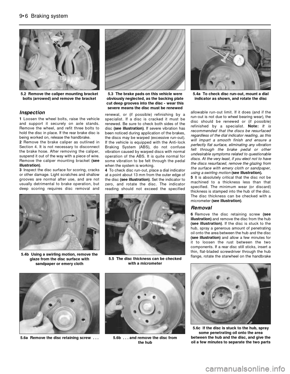
Inspection
1Loosen the wheel bolts, raise the vehicle
and support it securely on axle stands.
Remove the wheel, and refit three bolts to
hold the disc in place. If the rear brake disc is
being worked on, release the handbrake.
2Remove the brake caliper as outlined in
Section 4. It is not necessary to disconnect
the brake hose. After removing the caliper,
suspend it out of the way with a piece of wire.
Remove the caliper mounting bracket (see
illustration).
3Inspect the disc surface for scoring, cracks
or other damage. Light scratches and shallow
grooves are normal after use, and are not
usually detrimental to brake operation, but
deep scoring requires disc removal andrenewal, or (if possible) refinishing by a
specialist. If a disc is cracked it must be
renewed. Be sure to check both sides of the
disc (see illustration). If severe vibration has
been noticed during application of the brakes,
the discs may be warped (excessive run-out).
If the vehicle is equipped with the Anti-lock
Braking System (ABS), do not confuse
vibration caused by warped discs with normal
operation of the ABS. It is quite normal for
some vibration to be felt through the pedal
when the system is working.
4To check disc run-out, place a dial indicator
at a point about 13 mm from the outer edge of
the disc (see illustration). Set the indicator to
zero, and rotate the disc. The indicator
reading should not exceed the specifiedallowable run-out limit. If it does (and if the
run-out is not due to wheel bearing wear), the
disc should be renewed or (if possible)
refinished by a specialist. Note:It is
recommended that the discs be resurfaced
regardless of the dial indicator reading, as this
will impart a smooth finish and ensure a
perfectly flat surface, eliminating any vibration
felt through the brake pedal or other
undesirable symptoms related to questionable
discs. At the very least, if you elect not to have
the discs resurfaced, remove the glazing from
the surface with emery cloth or sandpaper,
using a swirling motion (see illustration).
5It is absolutely critical that the disc not be
machined to a thickness less than that
specified. The minimum wear (or discard)
thickness is stamped into the hub of the disc.
The disc thickness can be checked with a
micrometer (see illustration).
Removal
6Remove the disc retaining screw (see
illustration) and remove the disc from the hub
(see illustration). If the disc is stuck to the
hub, spray a generous amount of penetrating
oil onto the area between the hub and the disc
(see illustration)and allow a few minutes for
it to loosen the rust between the two
components. If a rear disc still sticks, insert a
thin, flat-bladed screwdriver through the hub
flange, rotate the starwheel on the handbrake
9•6 Braking system
5.6c If the disc is stuck to the hub, spray
some penetrating oil onto the area
between the hub and the disc, and give the
oil a few minutes to separate the two parts
5.6b . . . and remove the disc from
the hub5.6a Remove the disc retaining screw . . .
5.5 The disc thickness can be checked
with a micrometer5.4b Using a swirling motion, remove the
glaze from the disc surface with
sandpaper or emery cloth
5.4a To check disc run-out, mount a dial
indicator as shown, and rotate the disc5.3 The brake pads on this vehicle were
obviously neglected, as the backing plate
cut deep grooves into the disc - wear this
severe means the disc must be renewed5.2 Remove the caliper mounting bracket
bolts (arrowed) and remove the bracket