ECU BMW 3 SERIES 2002 E46 TV Function Retrofit Kit Installation Instruction Manual
[x] Cancel search | Manufacturer: BMW, Model Year: 2002, Model line: 3 SERIES, Model: BMW 3 SERIES 2002 E46Pages: 16, PDF Size: 0.55 MB
Page 3 of 16

EN/3
Retrofit kit No. 65 50 0 143 549
Installation Instructions No. 01 29 0 143 558 Issue date: 03.2002
Important information
The retrofit kit is for use within the BMW dealership organisation only.
Subject to technical modifications.
Target group
The target group for these installation instructions is specialist personnel trained on BMW cars with the
appropriate specialist knowledge.
All work must be completed using the latest BMW repair manuals, circuit diagrams, servicing manuals and
work instructions in a rational order using the prescribed tools (special tools) and observing current health and
safety regulations.
Installation information
The installation of the aerial is shown on the left-hand side of the bumper, proceed in the same way on the
right-hand side of the bumper.
Refer to the instructions for use of Sikaflex-221 (Saloon only).
Observe the tightening torque values for screw connections. The required tightening torque values are set
out in the part information system (TIS).
Ensure that the cables/lines are not kinked or damaged as you install them in the car.
The installed cables are to be secured with cable ties.
If the specified PIN chambers are occupied, bridges, double crimps or twin-lead terminals must be used.
After the installation work the retrofit TV function must be coded using DIS or MoDiC via the
Retrofit
path.
Information on operation
The TV function is only active when the car is at a standstill.
Tools required
DIS or MoDiC
Removal clips (65 5 400)
Special material required (Saloon only)
Sikaflex-221 (81 22 9 407 533)
Page 8 of 16
EN/8
Retrofit kit No. 65 50 0 143 549
Installation Instructions No. 01 29 0 143 558 Issue date: 03.2002
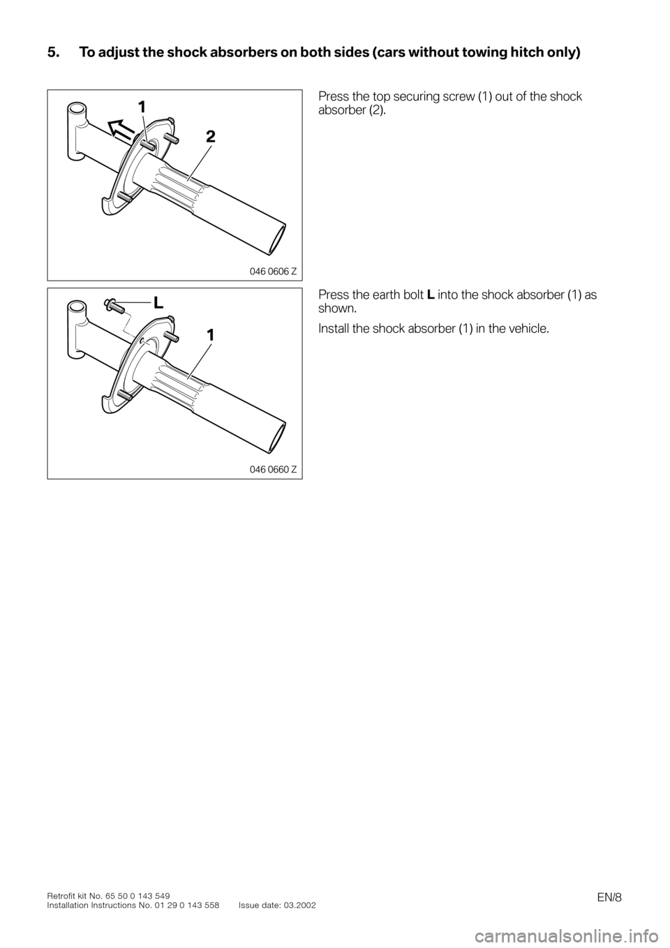
5. To adjust the shock absorbers on both sides (cars without towing hitch only)
0
0
00
Press the top securing screw (1) out of the shock
absorber (2).
0
Press the earth bolt
L
into the shock absorber (1) as
shown.
Install the shock absorber (1) in the vehicle.
046 0606 Z
1
2
046 0660 Z
L
1
Page 9 of 16
EN/9
Retrofit kit No. 65 50 0 143 549
Installation Instructions No. 01 29 0 143 558 Issue date: 03.2002
6. To install the aerial
0
0
00
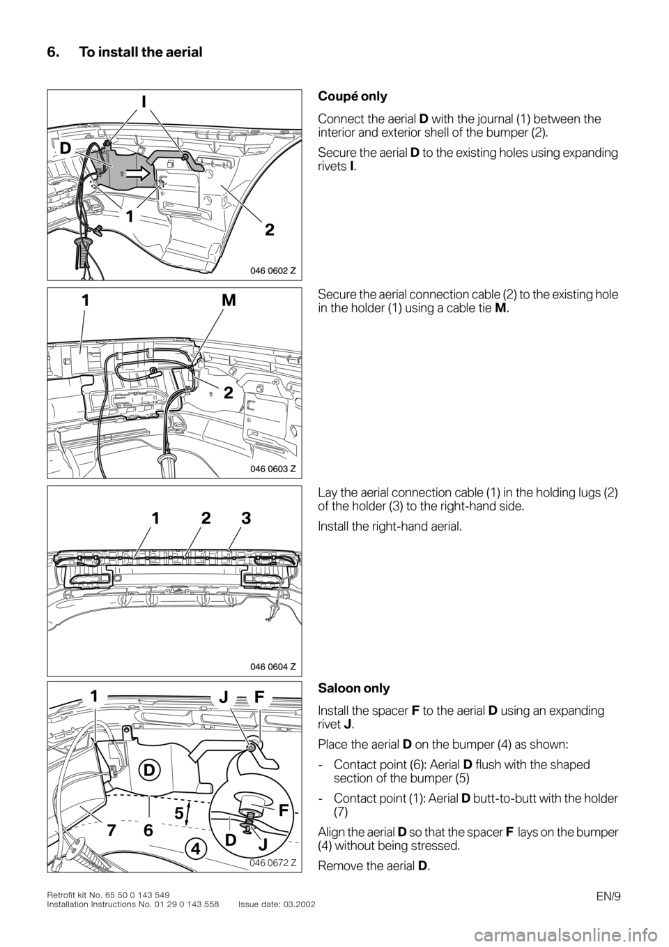
Coupé only
Connect the aerial
D
with the journal (1) between the
interior and exterior shell of the bumper (2).
Secure the aerial
D
to the existing holes using expanding
rivets
I
.
0
Secure the aerial connection cable (2) to the existing hole
in the holder (1) using a cable tie
M
.
0
Lay the aerial connection cable (1) in the holding lugs (2)
of the holder (3) to the right-hand side.
Install the right-hand aerial.
0
Saloon only
Install the spacer
F
to the aerial
D
using an expanding
rivet
J
.
Place the aerial
D
on the bumper (4) as shown:
- Contact point (6): Aerial
D
flush with the shaped
section of the bumper (5)
- Contact point (1): Aerial
D
butt-to-butt with the holder
(7)
Align the aerial
D
so that the spacer
F
lays on the bumper
(4) without being stressed.
Remove the aerial
D
.
046 0602 Z
I
D
2
1
1M
2
046 0603 Z
046 0604 Z
123
046 0672 Z
5
D
1
4
67
FJ
F
D
J
Page 10 of 16
EN/10
Retrofit kit No. 65 50 0 143 549
Installation Instructions No. 01 29 0 143 558 Issue date: 03.2002
6. To install the aerial
0
0
0
00
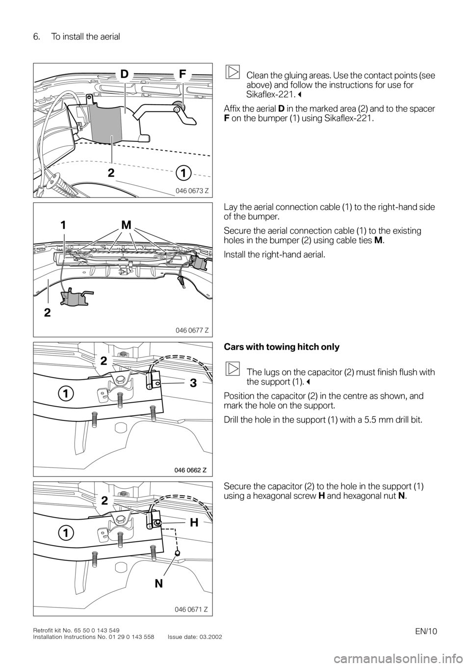
Clean the gluing areas. Use the contact points (see
above) and follow the instructions for use for
Sikaflex-221.
"
Affix the aerial
D
in the marked area (2) and to the spacer
F
on the bumper (1) using Sikaflex-221.
00f
Lay the aerial connection cable (1) to the right-hand side
of the bumper.
Secure the aerial connection cable (1) to the existing
holes in the bumper (2) using cable ties
M
.
Install the right-hand aerial.
0
Cars with towing hitch only
The lugs on the capacitor (2) must finish flush with
the support (1).
"
Position the capacitor (2) in the centre as shown, and
mark the hole on the support.
Drill the hole in the support (1) with a 5.5 mm drill bit.
0
Secure the capacitor (2) to the hole in the support (1)
using a hexagonal screw
H
and hexagonal nut
N
.
046 0673 Z
21
FD
046 0677 Z
1
2
M
046 0662 Z
1
3
2
046 0671 Z
1
H
N
2
Page 11 of 16
EN/11
Retrofit kit No. 65 50 0 143 549
Installation Instructions No. 01 29 0 143 558 Issue date: 03.2002
6. To install the aerial
0
0
0To install the aerial0
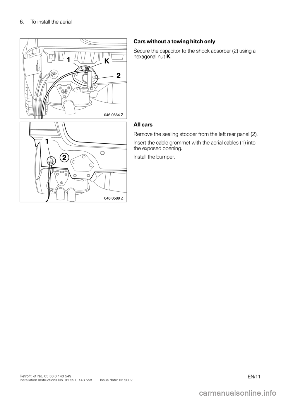
Cars without a towing hitch only
Secure the capacitor to the shock absorber (2) using a
hexagonal nut
K
.
0
All cars
Remove the sealing stopper from the left rear panel (2).
Insert the cable grommet with the aerial cables (1) into
the exposed opening.
Install the bumper.
046 0664 Z
2
K1
046 0589 Z
2
1
Page 13 of 16
EN/13Retrofit kit No. 65 50 0 143 549
Installation Instructions No. 01 29 0 143 558 Issue date: 03.2002
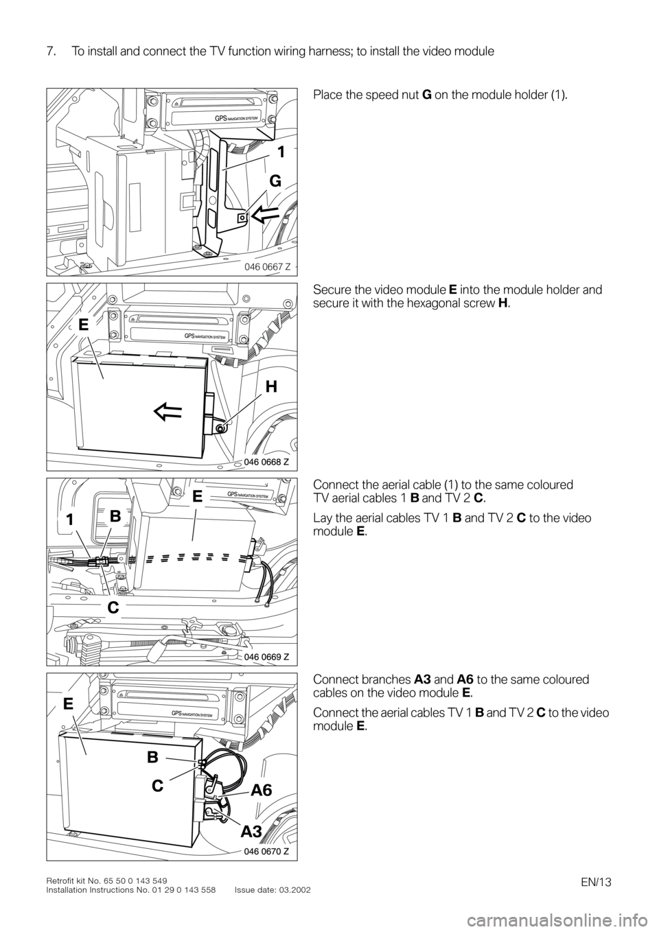
7. To install and connect the TV function wiring harness; to install the video module
0
0
0To install and connect the TV function wiring harness; to install the video module
00
Place the speed nut G on the module holder (1).
0Secure the video module E into the module holder and
secure it with the hexagonal screw H.
0Connect the aerial cable (1) to the same coloured
TV aerial cables 1 B and TV 2 C.
Lay the aerial cables TV 1 B and TV 2 C to the video
module E.
0Connect branches A3 and A6 to the same coloured
cables on the video module E.
Connect the aerial cables TV 1 B and TV 2 C to the video
module E.
046 0667 Z
GPSNAVIGATION SYSTEM
1
G
046 0668 Z
GPSNAVIGATION SYSTEM
H
E
046 0669 Z
GPSNAVIGATION SYSTEM
B1
C
E
046 0670 Z
GPSNAVIGATION SYSTEM
A3
A6
B
C
E